Schuman-Josaphat Rail Link in Brussels/B
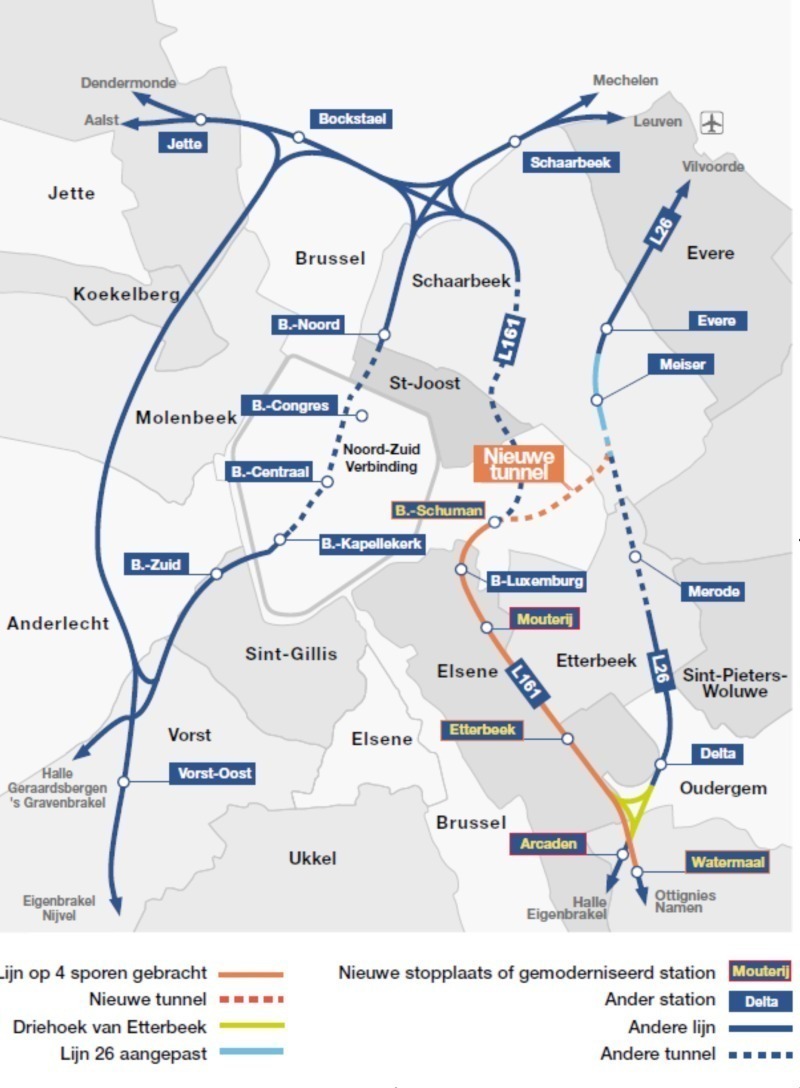

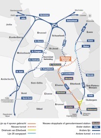
The tunnel under construction is part of the extended Schuman-Josaphat S-Bahn network around Brussels/B. This network is intended to improve the train frequencies and speeds on the rail lines up to 30 km around Brussels without reducing the quality of mainline connections. The following report examines work on the tunnel in closer detail.
The tunnel under construction is part of the extended Schuman-Josaphat S-Bahn network around Brussels/B. This network is intended to improve the train frequencies and speeds on the rail lines up to 30 km around Brussels without reducing the quality of mainline connections (Fig. 1). Based on current circumstances and probable future developments, it is essential to develop transport systems, which are a genuine alternative to cars. These future public transportation systems are designed to reduce motoring in the European metropolis and thus ward off the threat posed by traffic congestion.
A JV 60 % of which comprises companies belonging to the Dutch BAM group (Wayss & Freytag Ingenieurbau AG, Galère, CEI-De Meyer) and 40 % of firms not belonging to the BAM group (Jan de Nul, Franki Geoconsult) was awarded the contract to produce the new Schuman-Josaphat rail link.
The project is worth in excess of Euro 200 mill. and comprises 2 contract sections:
■ Contract section 1 serves to adapt the multi-modal Schu-man Station (railway/Metro), which is directly located at the European institutions (EU Com-mission, EU Parliament).
■ Contract section 2 constitutes the production of a 2-track tunnel totalling 1,250 m in length, comprising 2 sections using different construction methods.
Geology and Environmental Conditions
The tunnel drive passes through Brussels sands (quaternary) with banks of sandstone, which are decalcified locally. These sandstone banks are extremely irregular and practically eroded.
The link is located in the upper urban sector of Brussels and as a result the drive takes place more or less everywhere above the groundwater table. In addition there is the risk of possible cavities resulting from old underground rock quarries (sandstone).
The construction scheme is being partially undertaken (contract section 2) in a residential district, which is very susceptible to noise nuisance and generally to all inconveniences brought on by a construction site of this nature.
Work on contract section 1 takes place amidst the EU quarter, something which brings a series of consequences with it:
■ At the request of the client all external signs, which could refer to a construction site, must be restricted: no open construction shafts and a limited number of access shafts. The scheme must more or less be entirely carried out underground.
■ The areas available for setting up the construction site installations are extremely restricted by the surrounding conditions and the very dense traffic.
■ Additional security measures have to be introduced for every EU summit.
Applied Driving Methods
Different driving methods are used for producing this tunnel not simply to fulfil the general conditions imposed by the client but also to be able to master varying underground conditions (building foundations, existing road and rail tunnels etc.). Essentially 4 excavation methods are applied:
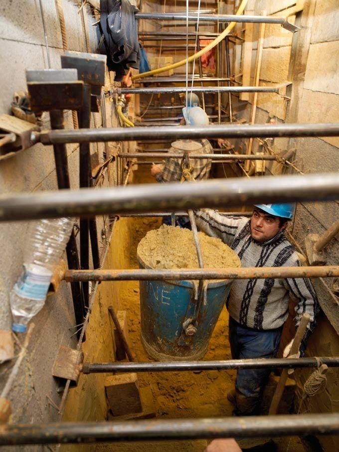
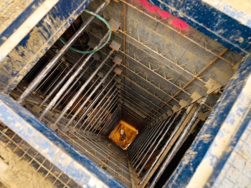
1. Manual Slots
As slotted wall equipment cannot be applied the slots are produced by trenchless means. Slots 1 m in width and 3 m long are created, which extend down up to 22 m. Following each 40 cm excavation phase, sheeting slabs are installed in the concrete, which are pressed against the surrounding soil by means of small steel props (Figs. 2 and 3).
As soon as a slot has reached the foreseen depth, it is reinforced and filled with concrete.
2. Rectangular Tunnel with an Area of 4 to 6 m² (Trenchless)
This construction method is applied for underpinning all foundations as well as for the exit for the Kortenberg road tunnel. It can be compared with the Cologne tunnelling method. First of all small pile wall slabs are placed horizontally in the soil. These slabs form the ceiling for the subsequent tunnel. Then excavation takes place protected by this ceiling and supporting slabs are installed at the sides.
By means of this technology tunnels with a 2 x 3 m cross-section and more than 150 m long are produced. Cross-passages are excavated with the same cross-section at many points from the main tunnel (Fig. 4).
Subsequently everything is reinforced and backfilled with concrete.
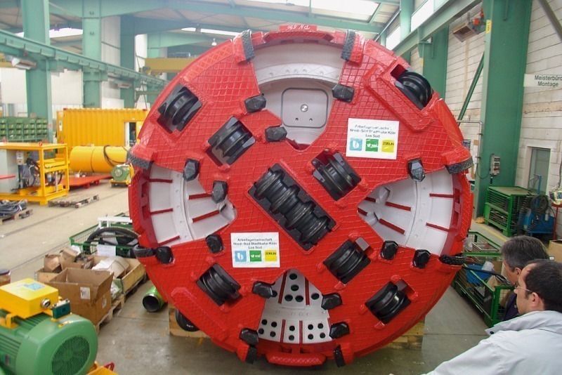
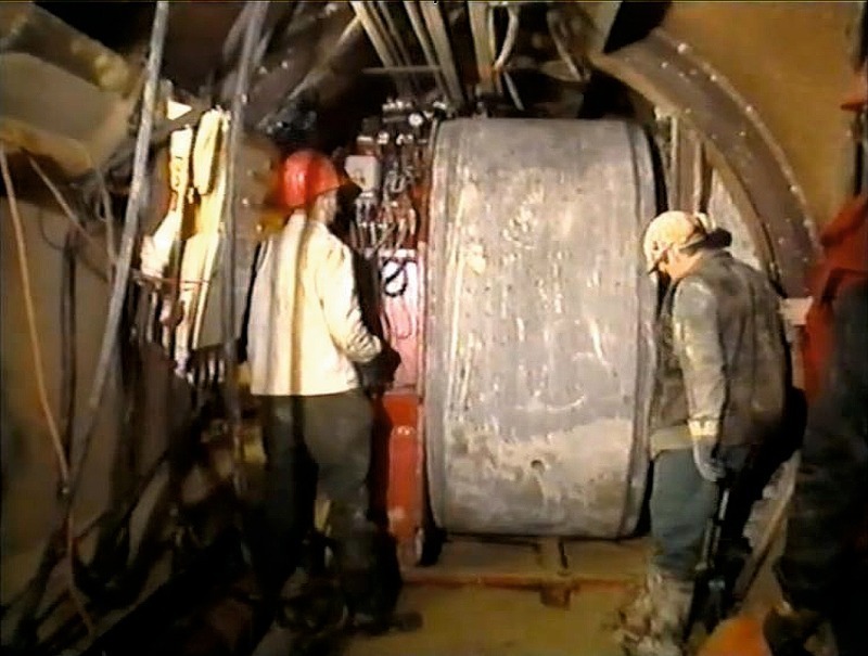
3. Pipe Drives DN 3000 with a Microtunnelling Machine
A Herrenknecht AVN 1800T with a DN 3000 cutterhead and reinforced skin (Fig. 5) is applied. This technology is used for producing the main drives DN 3000 and a pipe umbrella ceiling below a built-up area (residences).
4. Pipe Drives DN 2100 executed from the DN 3000
In this case the procedure is undertaken by mining means using a hydraulic pressure ring (Fig. 6). Lateral drives with smaller diameters are executed from the 3 mentioned main drives. Towards this end open cutting shoes are applied and the soil is extracted by mining means. These construction methods are employed to produce the roof and the walls of the future tunnel. Protected by these structures the tunnel bench is then excavated in a further construction phase.
Contract Section 1
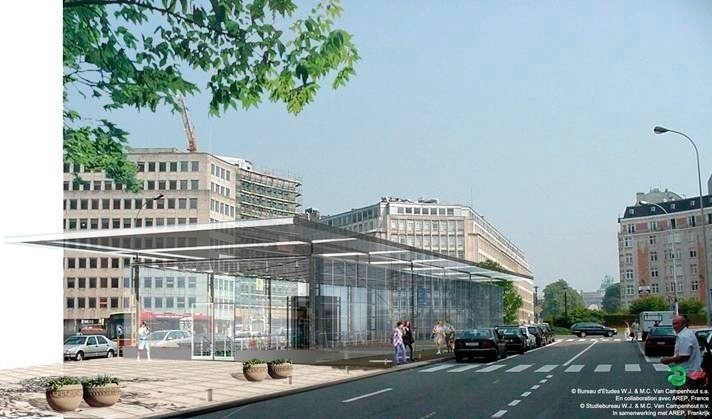
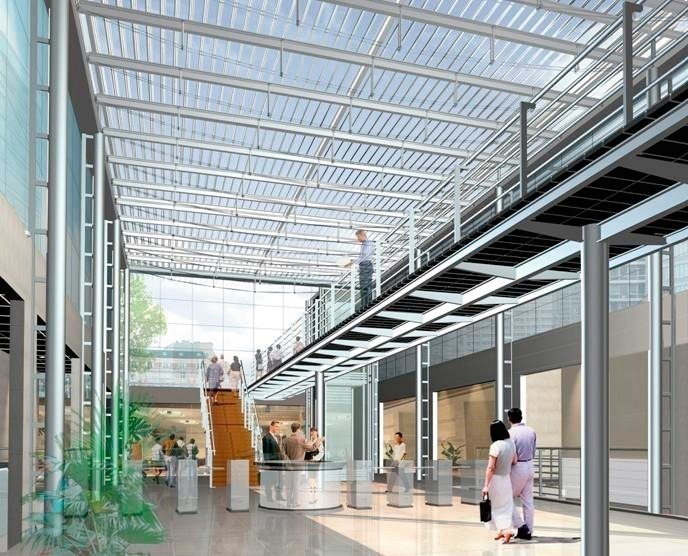
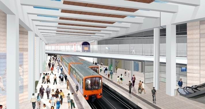
In contract section 1 the present Schuman Station (directly at the EU Council building) will be completely revamped. Firstly a fork to the new tunnel is produced and the station expanded to accommodate 4 platforms.
In addition the Metro line running along the Wetstraat is linked up so that a multi-modal junction for public transportation is produced here. The entire station is to be designed in such a way that as much natural light as possible can filter into the underground station. In addition a great deal of glass is to be used at the main entrance and in the area where the road tunnel is to be undertunnelled. The station is to be provided with 7 entrances, which will be set up around the Schuman Square (Figs. 7, 8 and 9).
Contract Section 2
Contract section 2 was split up into 2 sections of 870 and 380 m, with this division resulting from the different construction methods. The walls of the subsequent tunnels are produced by manual slots in both sections.
In the 1st section a part of the roof is built by 3 x 2 m tunnels located alongside one another. Towards this end these tunnels are temporarily supported with steel frames. Then they are backfilled with concrete so that underground beams are created, which jointly form the roof of the tunnel. The beams take over the load imposed by the structure located above and other buildings at the points, where the former foundations are to be found lying within the new tunnel’s cross-section.
A further part of the 1st section is to be excavated directly under an existing road tunnel, however without disturbing the tunnel foundations. In this case the carriageway of the road tunnel is used as a temporary roof structure. This enables the bench to be excavated beneath this concrete slab using mechanised means.
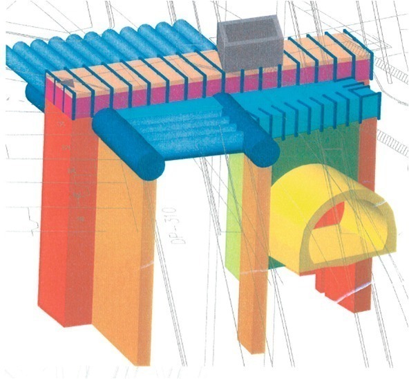
In the 2nd section the roof is produced by means of a tunnel boring machine (TBM). In the process 2 DN 3000 tunnels are excavated as curved drives (with radii of 270 and 400 m) using pipe driving. The tunnels are lined by steel pipes. The 2 bores are located between 14 and
25 m apart. Both DN 3000 drives are linked with each other by cross-passages (as in the 1st section) or by means of lateral drives DN 1800 (DA 2100), which are driven using mining means from the DN 3000 steel pipes (Fig. 10).
Additional general Conditions for the 2nd Section of Contract Section 2
Access to the underground construction site for the 2nd section is only possible via 2 shafts, which are roughly 110 m apart. The 2 DN 3000 pipe drives are executed from a central starting shaft towards the target shaft at a depth of roughly 9 m.
The 2 other pipe drives each some 290 m long are also executed at a depth of about 7 m from this central starting shaft as well, albeit without the possibility of retrieval. As a result the TBM (without reinforced skin) has to be brought back twice through the tunnel once it is produced.
As the pipe and tunnel drives take place directly beneath the cellars and foundations of the surrounding houses, an extensive monitoring system was installed above the entire construction route, which measures the absolute and differential settlements. In order to counter possible settlements outside the permissible values, various compensation systems were foreseen. Depending on the construction zone hydraulic jacks or compensation grouting were applied.
The noise limit values in contract section 2, section 2 are permitted to amount to 80 dBA between 7am and 7pm; 60 dBA must not be exceeded between 7pm and 7am and at weekends. These values apply for work carried out on the surface and installations set up 7 m away from the houses.