Special Steel Structure for the Schwäbisch Gmünd Tunnel


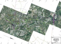
Since spring 2008 work on the bypass for Schwäbisch Gmünd/D has been in progress. Towards this end the B 29 federal highway is being laid in a 2,230 m long section under the town. Roughly 1.7 km of this section is being driven by mining means. Cut-and-cover sections 315 and 228 m in length link up with it in the east and west.
The work was awarded to the JV Tunnel Schwäbisch Gemünd consisting of the companies Ed. Züblin AG, Baresel GmbH, G. Hinteregger & Söhne Baugesellschaft m.b.H. and ÖSTU-STETTIN Hoch- und Tiefbau GmbH. The client is the Federal Republic of Germany represented by the Regional Council in Stuttgart.
The new development of the B 29 is expected to provide considerable relief for the inhabitants of the town of Schwäbisch Gemünd. At present the federal road runs through the middle of the town. As a main traffic artery it links Allen with Stuttgart running through the Remstal and serves as an access for the motorways A7, A8 and A81 in the region. Long tailbacks, especially during peak morning and evening hours, are customary.
The trenchless section comprises the 1,685 m long main tunnel, which is to be operated as a 2-way tunnel. It is to be flanked by an evacuation tunnel over its entire length and linked via 6 cross-passages set at
250 m gaps.
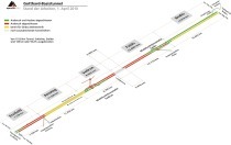
The exhaust air centre is situated in the middle of the tunnel. The electricity tunnel and the ventilation tunnel fork off from the breakdown bay. Both these structures are linked with each other via the room for the ventilation machinery. The 110 m deep exhaust air shaft is connected to the northern end
of the ventilation tunnel. It reaches the surface close to the Linden-first observation point and is topped by a 30 m high stack.
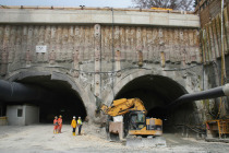
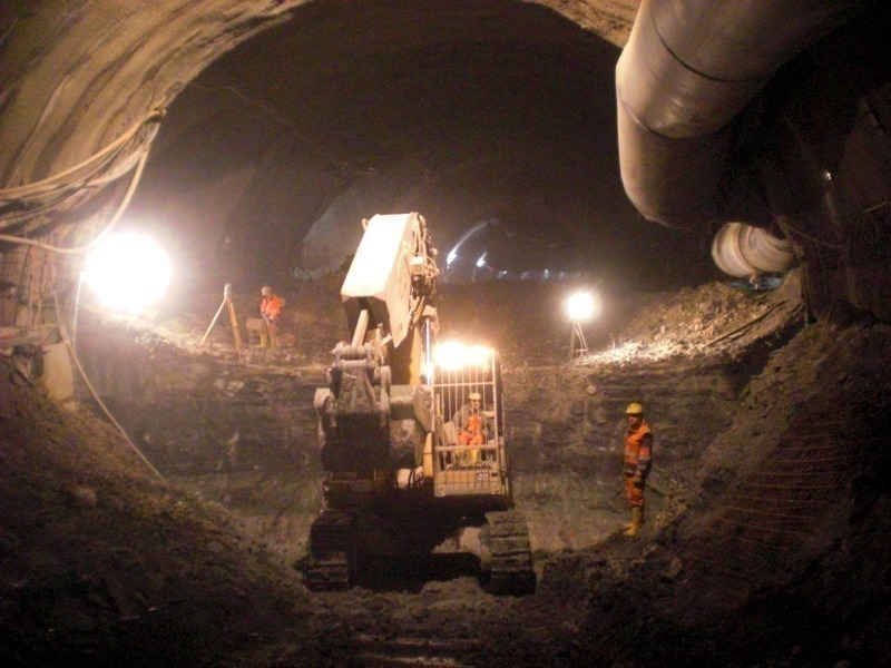
On account of the restricted conditions in the town centre the 2 tunnel bores can only be driven from one side. The evacuation tunnel can only be partially made use of for the construction site logistics on account of its 20 m² cross-section. Thus the utilisation of the cross-passages and an optimised construction cycle are of special importance.
The main tunnel is driven with an approximately circular profile, with follow-up bench and base invert. The scheduled general conditions call for parallel work so that there are 3 priority operating points once work on the inner shell begins. These are interrupted several times at the special structures for the exhaust air centre, the 2 breakdown bays and cross-passages as well as the sealing rings.
Geology andExcavation
The tunnel route is located in medium keuper. The excavated cross-section runs practically over its entire length along the boundary between upper coloured marls (km 3) and the intermittent beds consisting of clay and sandstones belonging to lower Stuben sandstone
(km 4).
Whereas the separating line between km 3 and km 4 is very consistent, the intermittent beds of the Stuben sandstone vary to a large extent on account of their thickness and strength. In addition there is the shallow tunnel overburden primarily in the proximity of the portals. Furthermore railway facilities as well as the River Rems are undertunnelled with only small gaps to spare.
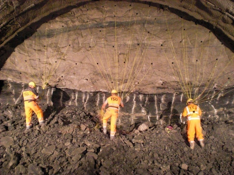
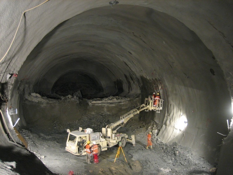
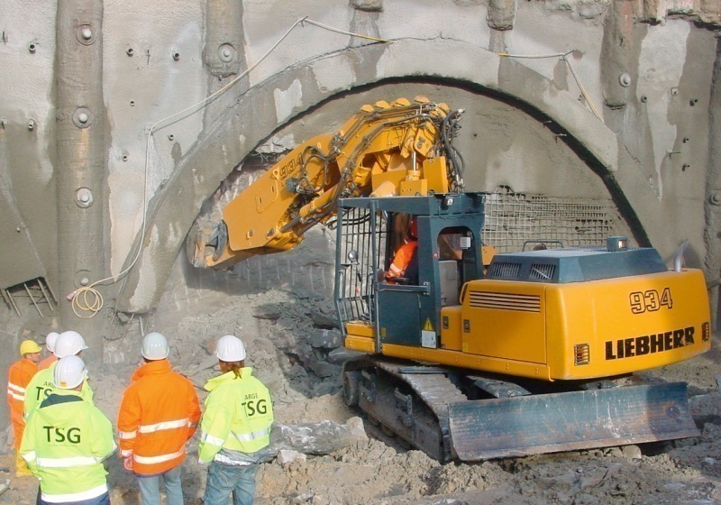
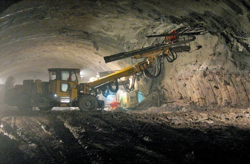
As a consequence large parts of the structure are driven protected by pipe and spile umbrellas. The rock is removed by drill+blast and excavators or a combination of both methods, known as mixed-face excavation. The lengths of advance vary between 80 cm in VKL 7A.3 and 2.00 m in VKL 3. Double lengths of advance are possible in the wall.
Fork Structure in the Exhaust Air Centre
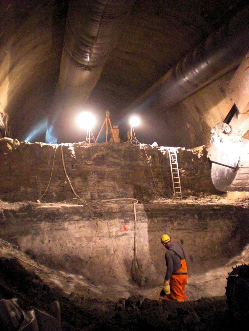
The above described cutting of special structures with large cross-sections in conjunction with geological intermittent bedding calls for particular attention during extraction and supporting, so-called intermediate construction states.
The tunnel bores are connected to each other via cross-passages at regular intervals. Typically these secondary structures fork off from the main structure at wall height, thus having a smaller cross-section and can be worked “ahead”.
The required production activities include the successive removal of the already existing cavity support along the main tunnel as well as the adapting and recreation of the support in the intersection area up to the first regular length of advance in the forking area. The adaptation section runs over 1 to 3 lengths of advance and is essentially comparable with regular driving operations in a vertical face. However it has to be observed in this case that the excavation and loosening work takes place in an area, which was previously penetrated by the main structure and can be accordingly loosened.
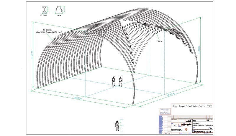
The construction of the supporting agents, the support arches is of particular importance. This especially applies where plate girders such as HEB or GI girders are concerned. A customary description of services for producing the intersection reads: “Adapt the arches on the spot during the drive and weld to the arches of the main tunnel. Separate the arches at the intersection according to need”. The same applies to the present project, where Type GI 120 arches are applied. The description makes no reference to the geometry and dimensions of the structures concerned. In actual fact the above situation requires qualified welding under site conditions including adaptation of the arch geometry. Apart from the surrounding conditions dust, ingressing water, etc. there is a further problem complex: usually no suitable skilled staff with welding qualifications in accordance with DIN EN 287-1 are available among the driving crew. This gap can be closed from case to case by resorting to workshop personnel.
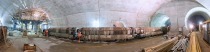
The 6 cross-passages between the 2 tunnel bores result in 12 intersections. On account of their size and location local adaptation is feasible. The task involving the 2 ventilation tunnels forking from breakdown bay 2 is more sophisticated. Both structures possess an identical excavated cross-section totalling 250 m², which is split up into crown, bench and invert. The 3-dimensional intersection line runs correspondingly to the roof.
During removal first of all the arches are separated and withdrawn, which are located in the centre of the field of the cross-section being tackled. After the roof parts are removed, the foot sections remain, which still form a partial bond with the shotcrete shell. They are also demolished. In other words from the very outset there is an unsupported area running from the crown base to the roof. Possibly the arches for the forking structure rotated by 90° must be mounted below this area after first securing it with shotcrete. In the case of the lattice girder arch this can be accomplished by dint of the type of arch alone. The structure as such with individual steel bars and relatively low intrinsic weight helps in the process. The plate girder on the other hand finds no grip on the already existing structure. Before assembling the 2 structural parts the ends of the girders have to be adapted to the intersection angle. As a result the construction tolerances have a substantial role to play: tilting, twisting and the position in the main tunnel lastingly influence lengths and angle of the arches that fork off. In the best case scenario these effects resolve themselves when they are joined together; at worst they augment each other.
The complex activities for adapting and joining the steel structure have to take place overhead from a working cage. Owing to the iterative adaptation on the spot the times required until the new temporary support has been created are hard to predict. In the event of tricky geological conditions with spalling, crumbling, ingressing water etc. this state cannot be tolerated.
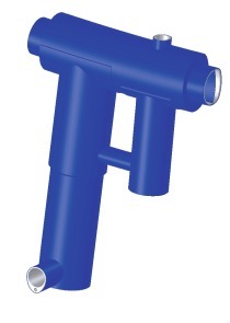
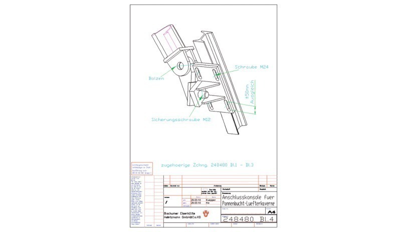
The responsible JV developed a special structure for the fork on the basis of its experiences with the prevailing geology in conjunction with its tunnel arch supplier (Bochumer Eisenhütte Heintzmann GmbH & Co. KG). The aim was to devise a fork structure which does without welding connections, can be assembled in the shortest possible time underground, permits acceptable on-site tolerances and also leads to no or only little more effort during the customary loosening and supporting work.
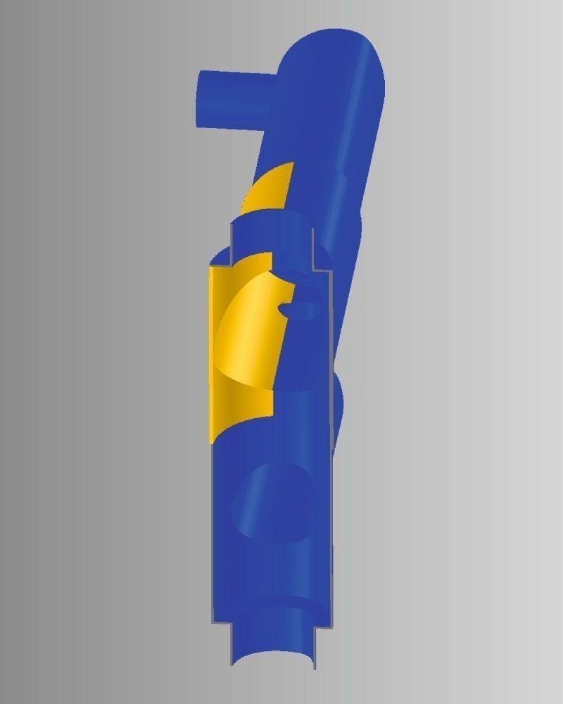
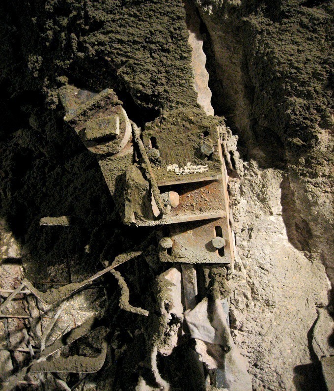
The outcome is a bracket structure with articulated bearings, to which the extendible TH arches in the area just tackled can be attached. Screws and bolts are used for attaching. The TH arches adapt to the already existing breakdown bay arches via clamps regarding their length and actual position.
Alterations to the angle are compensated for by a swivel joint, further corrections of position can be undertaken via elongated holes in the bracket plates. The fork structure connects at a second level beneath the breakdown bay arches, as a result of which these are installed with a 230 mm super-elevation. The GI arches for the enlarged main tunnel are installed in the form of special arches. They are provided with stops to accommodate the brackets when they are subsequently installed. The segment lengths are devised in such a way that scheduled dismantling when producing the intersection is possible.
The position of the bracket plate had to be checked by measurements during the excavation. The tunnel crew must adhere to the prescribed construction tolerances, as they are contained in the special steel structure design. The connecting area itself and the adjoining arch joint are well protected by an air cushion membrane. This prevents impurifications resulting from shotcrete and facilitates the following working steps. During the dismantling process the arch section to be removed can be loosened without tearing the remaining part away from its anchorage by chisel work. Then the workers mount the connecting bracket and prepare the TH profiles on the floor, by employing the clamping joint connections to ensure the profiles are the required length. Raising and bolting the TH arches round off the work.
Summary
The devised fork structure was praised unanimously as a very good solution by the foremen and construction managers involved after its successful application. It provided speedy assembly and in turn rapid securing of the cavity with considerable advantages in conjunction with industrial safety. The added costs ensuing for the special structure and a technical super-elevation of the tunnel sections affected are transparent from the very outset.