Additives to master major Permeabilities for EPB and Slurry TBMs
As a result of the ever-greater spread in fields of application for TBM drives in tunnelling, the process technology of the driving methods must also be adapted. This includes the mastering of high permeabilities during drives with active face support. The following report examines the related theory and a practical case provided as an example
1 Background
High permeabilities entail the risk that perhaps it is not possible to secure the required support needed for the face during the drive as well as in the case of compressed air accesses. Should the support fail on the surface of the face the outcome is usually overbreak and increased settlements arising from it or even cave-ins.
This problem complex has been identified by the construction industry and new solutions have been constantly developed to help minimise the risks involved during TBM excavations. Recently for example 2 EPB drives were successfully executed in the Hungarian capital Budapest, which had to cope with extremely high demands placed on the face support owing to the high permeabilities encountered in part-sections.
2 Theory
2.1 EPB Principle
Additional volumes of soil accrue in the extraction chamber owing to the TBM moving forward in the soil; the shield operator holds just as much material in the extraction chamber through the controlled extraction of the material by means of the screw so that the supporting pressure remains stable. The tolerance that can be attained amounts to roughly 0.2 bar. The removed soil has to be mixed with additives to form an earth pulp to achieve an active face support. Depending on the prevailing conditions tenside, polymer and water can be applied as additives. The earth pulp that ensues becomes pasty after mixing and possesses compressible characteristics thanks to the air volume it contains. Owing to the extremely different densities of the earth pulp there is a tendency towards precipitation, to separation. This process is desired at the dumping stage, however it already occurs when at a standstill in the extraction chamber and considerably affects the behaviour of the earth pulp.
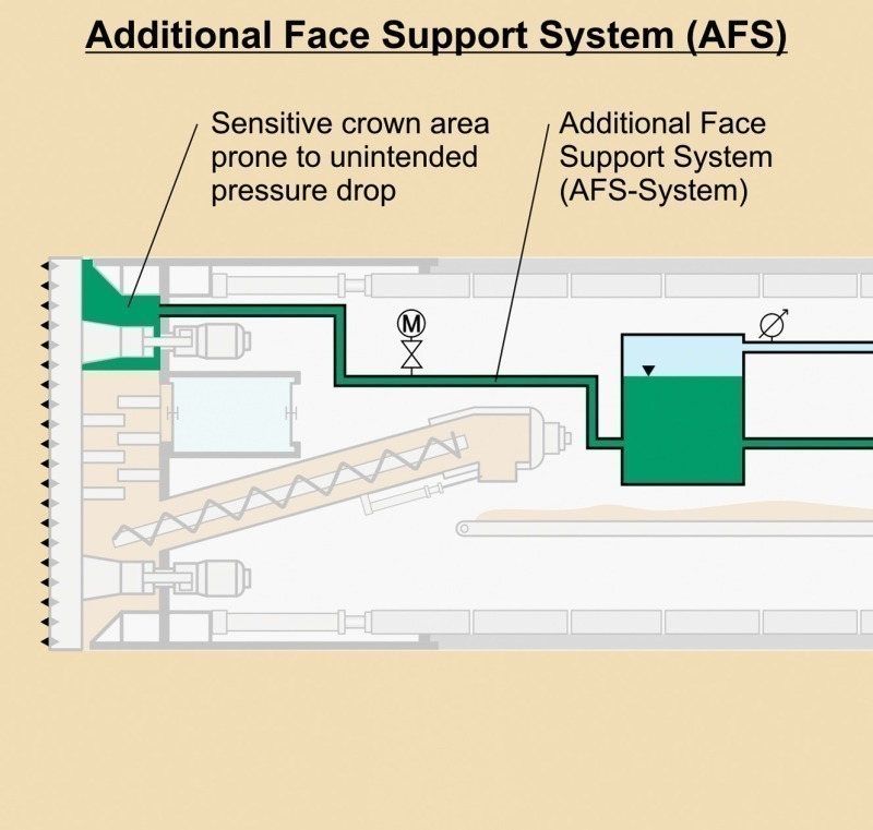
2.2 Additional Face Support System
The “Additional Face Support System” (AFS) is applied in order to prevent the earth pressure dropping during interruptions in driving (ring installation, maintenance etc.) (Fig. 1). If the TBM remains stationary no further volume is added to the extraction chamber through the shield passage. Should the foam bubbles explode in this state in the earth pulp, the released air diffuses in the surrounding subsoil. It is only possible to maintain the active face support with the earth pulp providing that an additional volume is added to the extraction area, which does not diffuse in the subsoil. Up till now the AFS has been applied in this situation, in order to inject a bentonite suspension into the extraction chamber when the earth pressure at the face drops.
The system is set up on the TBM trailers and consists of one or several tanks, which are filled with bentonite suspension and are directly connected with the roof area of the extraction chamber. The tanks are connected with a compressed air compressor via a control valve.
Should the effective support pressure drop in the extraction chamber below the predetermined amount, the AFS automatically injects bentonite suspension into the extraction chamber until the predetermined pressure in the extraction chamber is once again attained. In this way a fluctuation of the support pressure in excess of the 0.2 bar tolerance limit can be compensated.
Apart from this typical case the AFS is applied should it turn out to be difficult to produce the earth pulp with the excavated material and the artificially induced foam on account of coarse-grained soils. It was feared that this was the case during the case of the Budapest Metro in Hungary dealt with here.
3 Case Example Budapest Metro
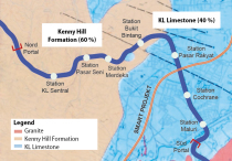
The JV BAMCO Tunnel and the Metro Construction Unlimited Partnership Budapest recently concluded the driving operations for Line 4 of the Budapest Metro. The parallel north and southbound tunnels were driven by means of 2 EPB TBMs, with 6.10 m bore diameter: The section between “Népszin-ház Straße” and “Keleti” Station is analysed in this report on account of the sophisticated geological conditions.
3.1 Geology
The tunnel passes underneath multi-storey buildings, roads and an elevated roadway in the historic old part of the city. The overburden below the building foundations amounts to roughly 8.8 m. The fundaments of the elevated roadway are located between the 2 tunnel bores and tail off some 3.2 m above the roof. The groundwater table in this section is located some 11 m above the roof.
The face conditions between “Népszin-ház Straße” and “Keleti” Station must be assessed as critical for EPB-TBMs on account of the extensive, coarse-grained subsoil both for the drive as well as for compressed air accesses.
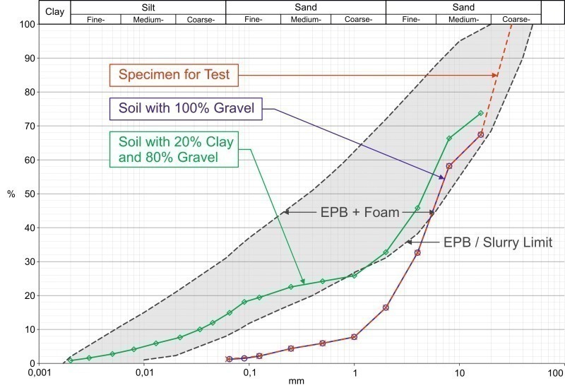
The geology in the zone that has to be excavated by and large comprises a layer of clay at floor level and a gravel layer in the roof. The permeability coefficient for the gravel lies between 8 x 10⁻⁵ m/s and 2 x 10⁻² m/s. The composition of the layers of soil in front of the face varies from 100 % clay to more than 80 % gravel. Fig. 2 shows the grading curves for the cases, in which the face consists of 80 % and 100 % proportions of gravel. Furthermore the section is presented in which it is generally possible to condition the soil.
As the proportion of gravel at the face grows the grading curve approaches the limit for the sector in which pure conditioning of the soil is still technically possible. In the project geology this limit is exceeded given an 80 % proportion of gravel. As a result the high share of gravel calls for a high degree of care when conditioning the earth pulp. If it is not possible to produce a reliable, stable earth pulp, then this has grave consequences on the face stability resulting in increased settlements right up to cave-ins.
3.2 AFS in Budapest
The AFS installed on the TBM used in Budapest had a capacity of 2 m³. The Budapest excavation was carried out with the usual EPB parameters. A “Foam Injection Ratio” (FIR) of 0.4 and a “Foam Expansion Ratio” (FER) of 9 were adopted for a comparative calculation. Taking these values the share of air in the earth pulp in the extraction chamber was determined to be roughly 8 m³. This volume has to be capable of being compensated by the AFS, so that stable face conditions can be assured even given lengthy standstills. The installed AFS was only capable of compensating for approx. 25 % of the maximum loss in volume that occurred.
Following an analysis of the prevailing situation Babendererde Engineers put forward proposals for preparing the AFS for the limit situation.
• Modification of the AFS circuit and increase in capacity of the AFS:
The AFS capacity was to be augmented through a further bentonite tank with a capacity of 2 m³ thus doubling the capacity to 4 m³. The second tank was connected with lines (100 mm diameter) parallel to the existing circuit. Pressure sensors and flowmeters were installed to register and control the determined pressure and the flow rate of the AFS.
• Modification of the AFS support medium:
It had to be assumed that on account of the geology prevailing in this tunnel section with a high proportion of gravel that the standard bentonite suspension in the AFS would not fulfil the required prerequisites to provide adequate face supporting. As a consequence lab tests were executed in order to recommend an adequate support medium.
3.3 Laboratory Tests
Experiments with various support mediums were designed to show whether and to which extent pressure limit variations with bentonite and polymers are capable of effectively supporting the face in spite of high permeabilities.
The soil made available for the tests was not representative of the coarse-grained soils, anticipated as a result of the Geological Report-. For this reason a representative soil was prepared in accordance with the grading curve for a 100 % proportion of gravel (Fig. 2).
The choice of the polymers took place in keeping with the grain sizes and the size of the AFS feedline. The swelling time of the individual polymers amounted to between 1 and 2 h. Care was taken to observe that the polymers could be easily mixed and were properly pumpable so that they could be used on site without any complications. The recipes applied for the suspensions assured long stability: it was possible to arrive at several weeks in this particular case.
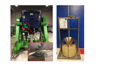
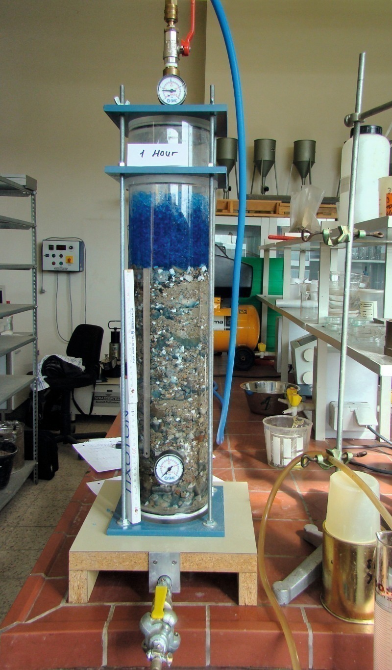
In the test presented in Fig. 3 first of all the exemplary soil was installed and completely saturated with water. Then the suspension was filled into the cylinder and 0.8 bar compressed air applied.
Given a pure bentonite suspension this penetrated the soil and was unable to establish the filter cakes necessary to transfer the support pressure at the face surface. As a result it was not possible to assure that the face was supported. For this reason largish pieces of polymer from Sawat Water Management were added to the bentonite suspension. Further test series with different grading curves for the polymers either on their own or featuring bentonite suspension ensued. In the process it was revealed that the application of varied grading curves for largish pieces of polymer best assured the formation of the filter cake. These largish pieces of polymer swelled to a size of 7 mm after adding water and caused the large soil pores to become clogged up. The bentonite suspension has then the capacity to effectively span the residual pores and establish the necessary support pressure.
The tests also showed that the addition of a straightforward polymer diameter or application without a bentonite suspension cannot assure the required sealing effect. It is essential that the grading curves are geared to the prevailing project geology in such cases of application.
3.4 Execution on the Construction Site
At the final stage prior to penetrating the highly permeable geology both TBMs were adapted for the suspension combining largish pieces of polymer and bentonite. Towards this end the volume of the AFS tank on the machines was doubled and the lines between the tank and extraction chamber fitted with automatic valves and sensors. The polymer-bentonite suspension was prepared outside the tunnel. The polymer-bentonite mix was transported to the machine ready for use.
In August 2010 the tunnel section between “Népszin-ház Straße” and “Keleti” Station was driven safely and successfully.
4 Outlook
In this case example a suspension of polymers combined with bentonite was applied in the AFS. However the field of application can be further expanded. Thus for instance suspensions comprising largish pieces of polymer and bentonite can be employed for slurry drives in geologies with high permeabilities. In the case of slurry drives the separability of the suspension has to be checked in addition to its pumpability. As in this case the throughput quantities of suspensions are also many times greater than in the case of an EPB excavation the economic effects for a project are substantially higher.
Apart from mastering the drive in high permeabilities the application of largish pieces of polymer is suitable in particular for compressed air accesses as well. Should a compressed air access be required in a section, where increased compressed air losses can be reckoned with, it is advisable to pump a stable suspension with a properly adjusted size of polymer into the extraction chamber prior to access and the related decrease in the support medium in order to close larger pores in the face effectively and thus cater for a constant air pressure cushion and secure face conditions.