Driving Galleries and Excavating Caverns for the Nant de Drance Power Station in Valais/CH
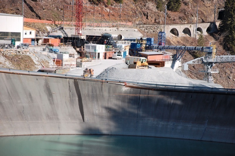
To make greater use of the still existing hydro power potential for supplying energy various major projects are being tackled in Switzerland. Towards this end pump storage technology is being applied, which calls for extensive underground systems of galleries and caverns. One of these projects is the Nant de Drance plant in Valais/CH. For this purpose a system of tunnels, galleries, shafts and caverns totalling some 15 km in length is under construction beneath the 2 existing dams at Emosson.
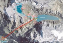
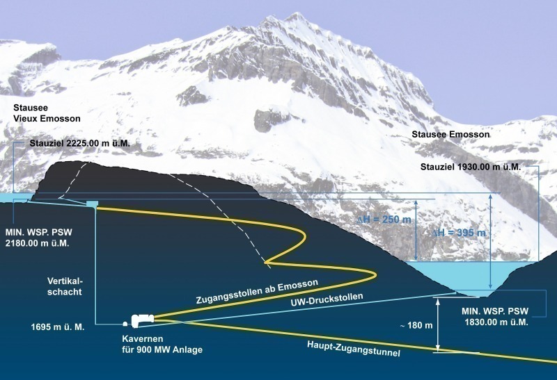
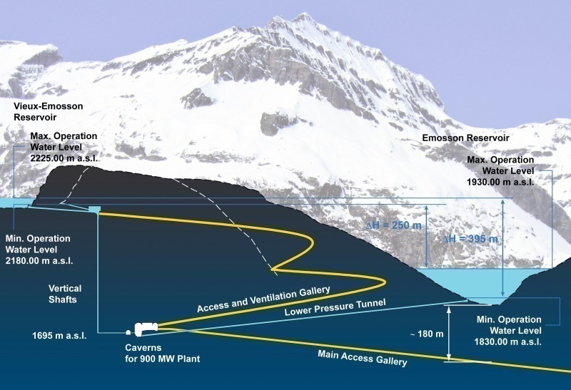
With investments of some 1.8 b. CHF (1.2 b. euros) the new Nant de Drance pump storage station is being built within the catchment area beneath the 2 dams at Emosson, operational since 1955 and 1975 respectively. The plants of the added facility, most of which are being produced underground take advantage of the gradient of 255 and 390 m between the new Vieux Emosson elevated by some 20 m (2,225 m ASL) and the Emosson dam (1,930 m ASL) to generate peak energy. Originally the project was planned to possess 4 pump turbines each of 150 MW producing 600 MW, it was decided to add to pump turbines to generate 900 MW. This calls for a great deal of adaptability on the part of AF-Consult Switzerland AG as the general project manager Thomas Ihly, dipl. Bauing. ETH Lausanne explained. This also applies to the construction operations that have been progressing since 2008.
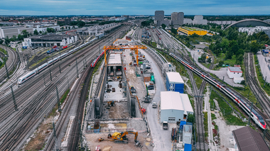
The new plants are located in the area of the municipality of Finhaut between Martigny and Chamonix close to the French border. Access is provided from Le Châtelard immediately alongside the existing SBB power station via a 5.6 km long gallery. This leads directly below the route of the Martigny – Chamonix narrow-gauge railway.
New Power Station Caverns represent the Heart of the Facility
The essential elements of this gigantic power station scheme are located underground. As a consequence the landscape panorama of this appealing mountain district in the Alps will remain virtually untouched. The underground engineering for the access tunnel, pressure shafts and caverns is accorded a key function. The main cavern with a length of 183 m, 52 m high and 32 m wide must be one of the biggest structures of its kind in the world. The excavated volume amounts to 230,000 m³, the rock overburden around 600 m.
In this turbine plant excavated from the rock 6 Francis pump turbines – Type Vario Speed – are being installed. Each of them generates 150 MW and altogether provide an 84 % rate of efficiency. Apart from the machine cavern a further major excavation is the transformer cavern with the dimensions 140 m long, 18 m wide and 15 m high. There are also 2 upperwater pressure galleries each 200 m long with 7.7 m internal diameter as well as two 440 m deep concrete-lined vertical shafts with an internal diameter of 7.0 m. Furthermore there are two roughly 60 m long steel armoured pipes with 5.5 m internal diameter with distribution lines each with 3.2 m internal diameter. Underwater 2 concrete pressure lines each 1200 m long also with 7.7 m internal diameter connect up to the 80 m long steel armoured pressure line.
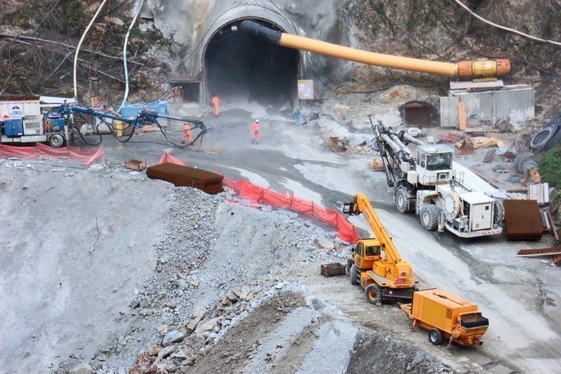
Main Access Tunnel with TBM Drive
Owing to the fact that the bulk of the power station key components are sited underground an extensive system of tunnels, galleries and chambers must be executed to access them. Towards this end a hard rock TBM is used for the 5.6 km long main access tunnel with an incline in excess of 11 % whereas conventional drill+blast is applied for the two 1.7 and 2.1 km long additional access galleries as well as for the other shafts and the caverns.
Geological Conditions
Good rock mechanical conditions were predicted for the underground structures on the basis of advance geological exploration. While driving the main access tunnel permo carboniferous and sandstone were forecast over the first 180 m from the portal in Châtelard, followed by mylonites/cataclasites over a distance of 340 m. Granite was expected over 1,040 m in the Aiguilles Rouges massif, then migmatic gneisses for 700 m, orthogneiss for almost 2,500 m and meta grauwacke over 965 m. These rocks are appraised as being good to very good for driving with the exception of the heterogeneous slate layers.
In actual fact the TBM drive had encountered a fault zone with large displacements between tunnel metres 1,600 and 2,000, leading to a delay in construction. This fault has now been overcome and in August 2011 the TBM reached tunnel metre 2,240. As the tunnel runs less than 200 m beneath the Emosson reservoir and the prevailing fault zone could drain off directly to the flanking area of the arch dam, special attention has to be paid to all possible water inbursts while it is being penetrated. Markus Weh and Francois Bertholet from the Marti Tunnelbau AG reported on this at an ETH Zurich congress. This means that the entire zone has first to be explored with preventer drill-holes. Should significant ingressing water be encountered then the rock in front of the face must be sealed by grouting. For passing beneath the reservoir, approaching the cavern area and penetrating other fault zones it is intended to investigate the rock in advance by means of destructive drilling without preventer.
Main Construction Section and Material Management
The main construction work, which has been awarded the bidding consortium Groupement Marti/Implenia (GMI), began in autumn 2008 with the excavation and supporting of the precut for the main access tunnel. The contract volume for the GMI consortium embraces the main access tunnel, which is 5,600 m long with a cross-sectional area of 70 m², the Emosson gallery system – 4,300 m in length with 45 to 50 m² cross-sectional area, the headraces with a length of 3,300 m and 47 m² cross-sectional area as well as 2 drop shafts – 440 m in height with 38 m² cross-sectional area along with the machine and transformer caverns as major components. In addition grouting and fixing operations as well as roughwork and interior lining jobs are involved.
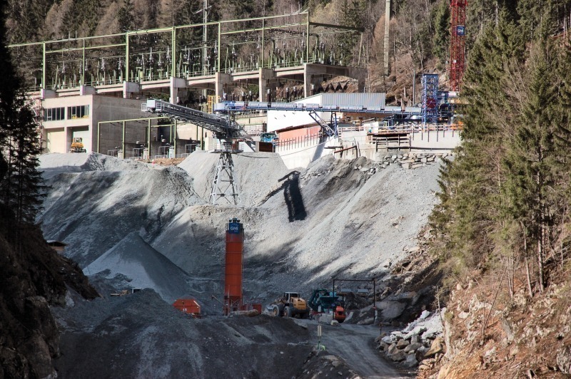
The GMI was also commissioned to prepare material for concrete gravel as well as to provide final storage for the excavated material. The total excavated volume for building this energy scheme exceeds 1.5 m. m³. Of this amount 20 % can be utilised for concrete production, the bulk of the excavated material is deposited in the Châtelard dump and integrated into the landscape as well as possible. A second repository capable of holding some 400,000 m³ is located at a height of roughly 2,000 m ASL on the fringe of the reservoir.
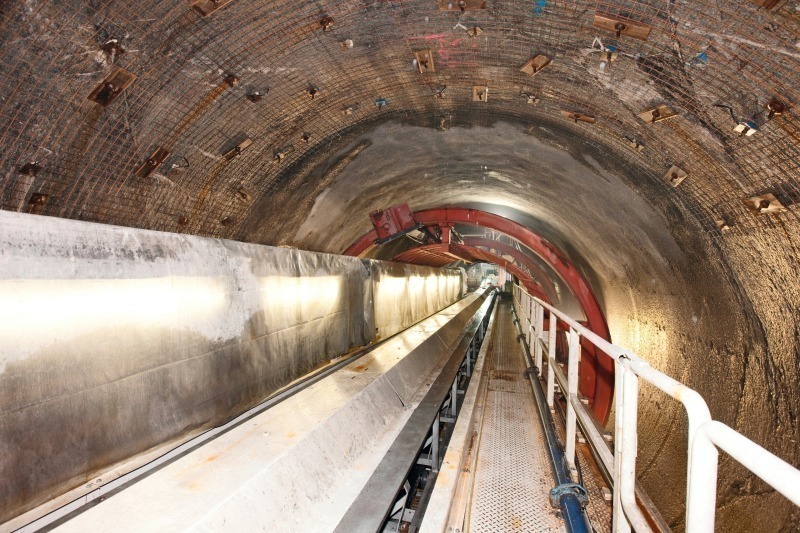
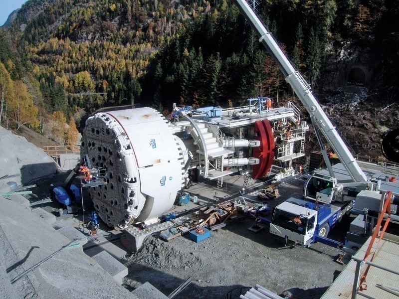
Tried-and-tested Herrenknecht TBM modified
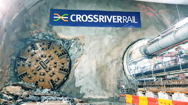
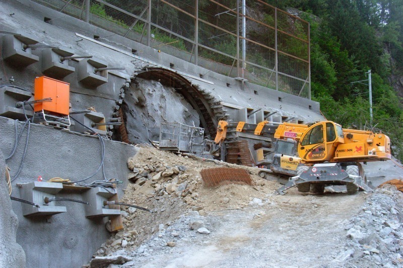
A 9.45 m diameter tunnel boring machine is being used by the Marti/Implenia consortium for driving the access tunnel. In the portal zone it runs below the railway line at a distance of some 3 m and is located in a soft ground zone comprising scree and rockfall material. Consideration had to be given to the fact that there was little space available for setting up the TBM at the portal.
The hard rock Herrenknecht TBM that was applied is one of the tunnel boring machines used for the Lötschberg Base Tunnel. According to Weh and Bertholet the Marti Technik AG carried out the necessary modifications in the L1 sector and constructing a new trailer including the belt conveyor.
The objective was to adapt the TBM to the specific project conditions including 12 % gradient, narrow 500 m curve radii as well as destructive advance drillings with and without preventer. The tunnel zone has to be sealed by grouting should water be discovered at critical points. The TBM possesses the parameters contained in Table 1 in accordance with these specifications.
Concept for L1 and Trailer
Compared to the Lötschberg Base Tunnel the platforms in the L1 section were greatly extended as can be gleaned from the congress report presented by Bertholet and Weh. The mesh placing unit and the cabs for the 2 drilling booms were excluded. The exploratory drilling unit is positioned centrally above the gripper in such a way that there is no need for the transport cradle above it. The shotcrete robot is also placed centrally at the front part of the platform. The anchor drilling units in L1 are located between the finger shield and platform and are capable of covering the entire tunnel profile. The anchors and the meshing are placed from the platform. The grouting drilling unit together with the upper part of the ring drilling unit carrier is first assembled when it is required. Drillholes for grouting in the floor are executed by a single-armed jumbo. Swellex anchors are placed in the types of profile most expected in the L1 sector. Two further drilling units are arranged in the L2 sector with which the holes for mortar anchors, the permanent tunnel support, are drilled. An arch setting units is located directly within the finger shield. The steel arches are transported forwards by means of a cradle over the exploratory drilling unit and shotcrete robot.
The trailer is 148 m long consisting of a total of 6 elements, requiring it to be preassembled from the side at the portal on account of constricted space conditions, lifted into position piece by piece and thrust forward. As the invert is first installed behind the trailer, supply vehicles run over the excavated base to the trailer. The back-ups run on a set of rails. All appliances, which carry or process liquids, had to be adjusted to the 12 % tunnel gradient. The excavated material is passed on to the tunnel conveyor system from the last back-up (Table 2).