Declined-shaft Tunnelling in St. Petersburg
The metro tunnels in St. Petersburg are running very deep. Several of the stations on the system had not been taken into service, because construction of the escalator accesses in the challenging geology had hitherto proved impossible using conventional tunnelling methods. A tunnel boring system, newly developed by Herrenknecht, has now driven large-diameter shafts at a 30° inclination to create access for 2 stations.
1 Introduction
1.1 The St. Petersburg metro
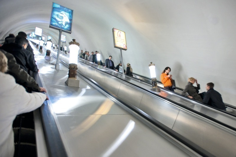
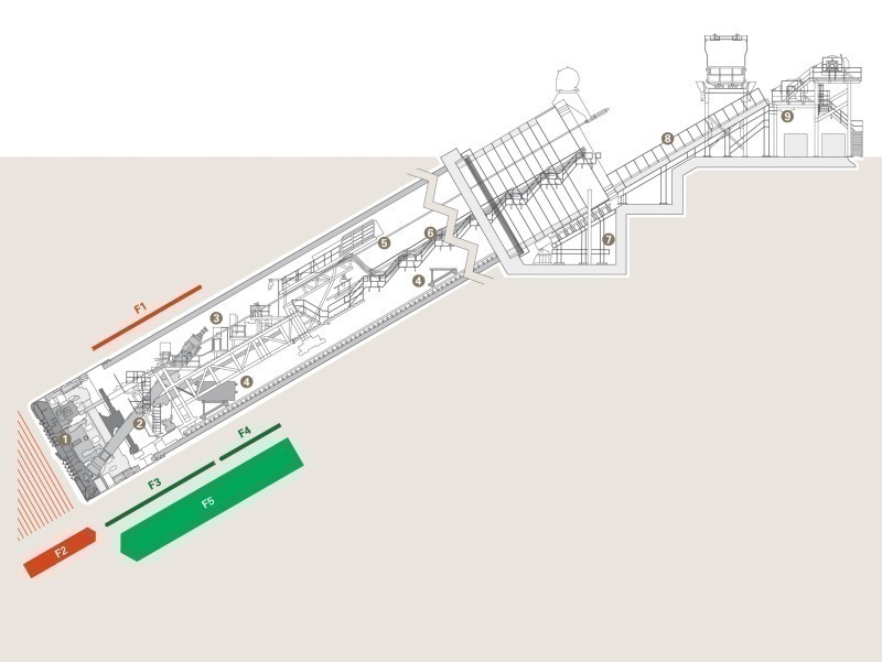
St. Petersburg was established by Czar Peter the Great in 1703 to secure strategically important access to the Baltic Sea for Russia. The city was built on the swampy ground of the Neva Delta – a fact that posed serious headaches for today’s civil engineers. The instability of the geologically young subsoil forced the metro tunnel constructors to plan their tunnels in the lower, geologically older, hard clay subsoil. At depths of as much as around 100 m, most St. Petersburg metro stations are connected to the surface by long escalators (Fig. 1). Some stations, however, are still passed by the trains without stopping, since they have no connection to the surface, so were inaccessible to passengers. To create access to these stations and enable ]
1.2 The challenge of constructing the access shafts
The commonly employed procedure is to temporarily freeze the subsoil, thereby solidifying it and making it water impermeable, to enable a shaft to be driven using conventional tunnelling methods. However, the freezing can result in uplift and then to settlement when the ground thaws out. Particularly in the urban area of St. Petersburg, with its rich architectural heritage, such risks militate against the use of the freezing method.
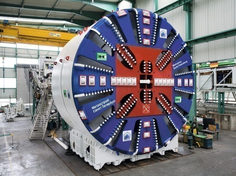
Mechanized tunnelling allows the settlement risk to be better controlled than when conventional methods and freezing are used. At the same time, the construction of a shaft inclined at 30° and with a length of only around 100 m places special requirements on mechanized tunnelling. New solutions needed to be found for the material logistics, the back-up system in an extremely short tunnelling length and, above all, securing the machine against uncontrolled sinking. A machine diameter of 10.7 m was determined, to allow for the size of the shaft required to accommodate 3 parallel escalators. The intention was to be able to recover the major components of the boring system from the blind shaft at the end of tunnelling, for reuse in other projects.
Herrenknecht was commissioned by the Russian construction company, OAO Metrostroy, to develop a machine concept for construction of an access shaft at the Obvodny Canal station and to design, construct and delivery a tunnelling machine to carry out the work. The following remarks relate to the implementation of the Obvodny Canal project, but also apply to the Admiralteyskaya follow-on project, which was commissioned after the successful completion of the first tunnel.
2 Implementation in machine design
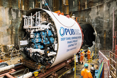
On the basis of the known geological parameters and in consultation with the customer, Herrenknecht developed the S-441 EPB Shield, which was designed, including the necessary site components, in line with the prescribed project characteristics (Table, Fig. 2).
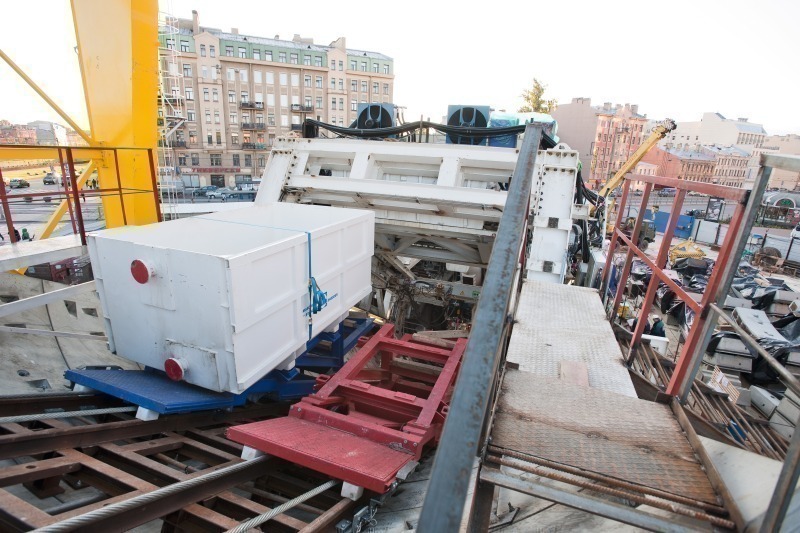
With an inclination of 30°, neither rubber-tired vehicles nor trains nor conveyor belts could be used to transport material in the tunnel. Sandwich conveyors, which tend to clog when used in cohesive clay, and a rack railway were also out of the question, since the gradient was too steep for these systems as well. The selected solution for transporting spoil and tunnel segments was a system operating with 2 winches and rail-borne cars, carrying spoil buckets (Fig. 3).
In addition to service and emergency brakes on the winch, local regulations required safeguarding against rope breakage on the winched cars. It was important that the braking impulse of the winched car should not be transmitted to the rail tracks and from there to the tunnel lining. The rope linkage to the winched car was therefore designed as a double rope, in order to comply with the required safeguarding against rope breakage. Furthermore, a slackline guard controlled synchronous running of the winch with the winched car.
It was essential for the EPB Shield’s screw conveyor to perform adequately at an angle of 50°. Test runs before use on the construction site demonstrated that, while the conveyor performance declined as the gradient increased, satisfactory performance was still achieved at the required angle of inclination.
The overall length of the tunnelling system had to be kept very short for the comparatively short bore in the Obvodny Canal project of just 97 m. A single 21 m backup was provided and the overall length of the entire tunnelling machine (shield and backup) was just 32 m. Construction of the back-up in the start-up shaft was restricted by the winch house in rear of the tunnel and therefore required installation of the back-up in 2 stages. For space reasons, the transformers to supply energy to the machine hydraulics were not installed on the back-up, but erected on the surface.
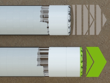
The very soft geology to be penetrated above the solid clayey soil layer comprised glacio-fluvial and fluvial deposits, in some cases with a high water content, providing very little resistance to the weight of the tunnelling machine: sand, silt and clay strata, which gained strength only with increasing depth. The center of gravity of a tunnelling machine is essentially located near the heaviest components – the cutting wheel and the cutting wheel drive. If the machine is tilted forward out of the horizontal, its net force no longer runs through the shield, which in “normal” horizontal use, transmits the inherent weight of the machine through the bedding to the surrounding ground. Instead, as the machine is tilted, the net force shifts to the cutting wheel plane. The inherent weight of the TBM would therefore produce a tendency for the machine to bury itself in an uncontrolled manner in the direction of the center of the earth.
To achieve the necessary stabilization of the shield and the entire tunnelling machine, Herrenknecht engineers developed a system using steel ropes secured to the shield. These introduce a tension into the upper half of the shield and apply torque to counteract the shield drift. The steel ropes run upwards through the shaft and are anchored in tubular piston cylinders on a reaction frame on the surface. The tubular piston cylinders allow controlled powered extension of the steel ropes, synchronized with the tunnelling advance (Fig. 4).
The plan allowed for the mechanized tunnelling to end in a cavern, once the required depth had been reached. All back-up and machine components were to be designed in such a way as to allow them to be disassembled in the shaft and winched out to the tunnel portal. It was planned to leave the shield skin in the shaft as part of the tunnel cladding. The shield was subdivided into 4 outer segments and 4 removable inner segments. This reduced the cost and effort of new production of the shield skin for each additional shaft.
The segment rings, each comprising seven standard segments with a key segment, at a segment length of just 1,000 mm, but a thickness of 500 mm, were adapted to the specific requirements of the project. The segments were cast in an existing segment production plant in St. Petersburg, using moulds supplied by Herrenknecht Formwork. The ring design took account of the force acting down the inclined plane of the tunnel bores, allowing for incomplete bonding between the tunnel segments and the surrounding rock. Additional bolted joints were inserted in the ring joints.
3 Construction site sequence
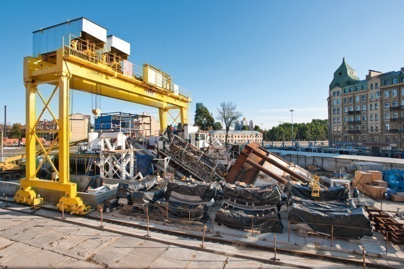
The tunnelling shield was installed in a horizontal position and, once completed, the weight of 650 t was tilted to 30°, using a swivel joint on the shield cradle. Two cylinders lifted the shield cradle to just before the tipping point and 2 additional cylinders supported the force of the machine acting down the inclined plane against the shaft wall. A steel structure was then used to secure the shield cradle in its final position (Fig. 5).
To ensure a tunnelling with minimal settlement, it was necessary for tunnelling and ring construction to proceed as smoothly as possible without holdups and interruptions. This, in turn, required smooth operation of the spoil logistics. To be able to load the winched spoil buckets in a shuttle operation, the screw conveyor was designed to enable it to swing over the buckets being loaded.
Right from the first meters of advance in the sealing block, the excavation chamber was filled as high as possible with spoil from the injection block in order to activate face support pressure on the TBM, in opposition to the force acting down the inclined plane. Once there was sufficient pressure applied to the machine, after the first segment rings had been installed, the tunnelling shield was steerable and controllable even without the cylinders used for the first meters of the start-up. The steel ropes, used to prevent the sinking of the tunnelling shield, were successfully used as a restraining system in the first shaft (Obvodny Canal) and in the second shaft (Admiralteyskaya) during the first half of tunnelling. In the second half of the advance, the restraining ropes had only little tension applied. Since the face support pressure in the excavation chamber increases with the depth of the machine, sufficient advancing thrust force can be activated to control the machine, so that the tensioning ropes were no longer required to stabilize the machine.
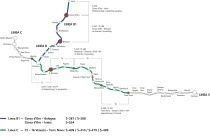
In the first shaft – for the Obvodny Canal – the OAO Metrostroy machine operators drove the inclined shaft machine for 97 m down to the 65 m deep metro station. In comparison with the actual tunnelling time, the machine installation time of 2.5 months took up a considerable part of the project. A further 3 weeks were required for the start-up procedure to the first remaining structural ring with the extension of the back-up. Average tunnelling production after the start of the advance (October 2009) was 1.5 rings daily (at a ring length of 1 m) with a maximum of 4 rings daily (Fig. 6). The final segment ring was installed and the tunnelling completed on 25 December 2009, with the station opened in an official ceremony 1 year later in December 2010.
In the summer of 2011, following refurbishment and delivery of a replacement shield skin by Herrenknecht, the installation was erected again not far from the western end of Nevsky Prospekt, the prestigious St. Petersburg boulevard and shopping area, ready to start work on a further metro station, Admiralteyskaya, which had been waiting for some years to be commissioned.
The second inclined shaft for the Admiralteyskaya station – with a length of 116 rings – was constructed between December 2010 and April 2011, at an average tunnelling rate of 1.3 rings daily (Fig. 7).
4 Settlement
Well ahead of commencement of tunnelling works, extensive investigation was carried out into the settlement behavior of the subsoil. Low-settlement tunnelling was the key argument in favour of employing mechanized tunnelling. At the commencement of tunnelling, the distance between the top edge of the machine and the earth surface was just 1 m. Before the TBM started its advance, the ground in front of the start-up shaft was solidified into a sealing block by injection work. At an inclination of 30°, the tunnel boring machine descends a 0.5 m for each meter of advance. The length of the sealing block in the first shaft advance at Obvodny Canal was restricted by the size of the site to a length of 10 m. The site was immediately adjacent to a four-lane main traffic route with a street car line running along the center, which had to be crossed. In terms of settlement control, the start-up phase of the inclined shaft machine posed the biggest challenge. With proceeding advance and increasing overlap over the tunnel crown, surface settlement became easier to control.
5 Disassembly in the shaft
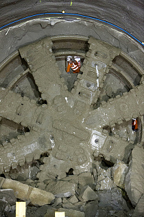
As planned, the machine was disassembled in the blind shaft. Since the machine advanced into an existing cavern next to the metro station, there were no problems in disassembling the cutting wheel with the aid of a winch in the shelter of this cavern.
6 Summary and perspectives
In collaboration with the customer, OAO Metrostroy, Herrenknecht developed a tunnelling system that, for the first time, successfully mastered a shaft with an internal diameter of 9,400 mm at an inclination of 30°. The escalator shaft to access the hitherto dormant Obvodny Canal metro station was quickly and safely produced in late 2009. A second use of the Herrenknecht S-441 EPB shield followed from December 2010 to April 2011, and a third use is planned at the Spasskaya station in December 2011.
Both the mechanized tunnelling technology used (tunnelling shield with back-up, start-up construction, control and support systems with cylinders and ropes) and the supplied components for operation of the construction site (segment formwork, crane) proved their capabilities in use. While mechanized production of inclined shafts has been successfully carried out many times in hard rock – for example in producing pressure shafts – the design of a tunnelling system for shafts in loose rock below groundwater level broke new ground. In corresponding geological situations, the system could also be used, for example, to drive access shafts to mines.