Söderleds Tunnel
Stockholm:
General Refurbishment of the Western Tube
The Söderleds Tunnel in the swedish capitol Stockholm was built in 1944 and is an important line connecting South to North of Sweden. The following article gives an overview of the refurbishment of the western tube.
Introduction
The Söderleds Tunnel („South Way Tunnel“) is a tunnel between the Central Bridge and the Johanneshov Bridge underpassing the island of Södermalm in Stockholm. Södermalm Island belongs to the city center of Stockholm. Approx. 1,580 m long and traverses the island from north to south with 2 tubes and 2 lanes each. On the stretch between Brännkyrkagatan and Folkungagatan an earlier tunnel called Södergatan had been built in 1944 in a cut-and-cover trench. Between 1964 and 1966, it was extended 150 m under Åso High School. The tunnel as it is today was started in 1984. The work was finished on schedule in January 1991 with the Clarion Hotel in the South End.
The tunnel is one of the main connections between north and south Stockholm. The AADT is around 80.000 cars a day.
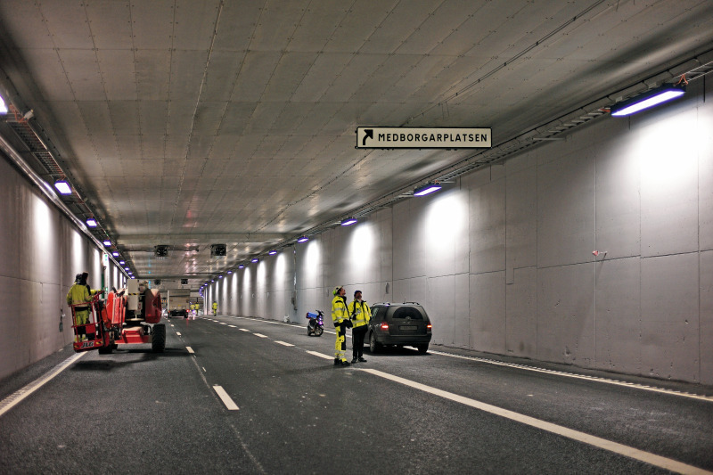
The design of the refurbishment was done in 2004. The eastern tube was divided in sections for a refurbishment and was closed 3 times between 2005 and 2009. For the western tube a complete refurbishment was the preferred solution to reduce closing time and cost. For the western tube the traffic was shut down the 4th of July and reopened the 27th of November, a few hours before planned schedule. During the works up the 120 people from 7 different nations worked in the tunnel, partly 24 hours a day.
The refurbishment was awarded to a joint venture of Strabag Sweden and E-Schakt. The client for the project was Trafikkontoret Stockholm. Täby BrandskyddsTeknik got the following works as subcontractor: fire protection, noise reduction and escape signs.
The upgrade includes the following works:
• Hydro-demolition of the damaged or chloride contaminated concrete areas at the tunnel walls
• Shotcrete lining
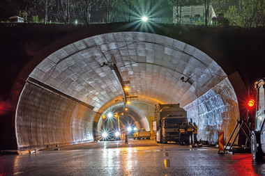
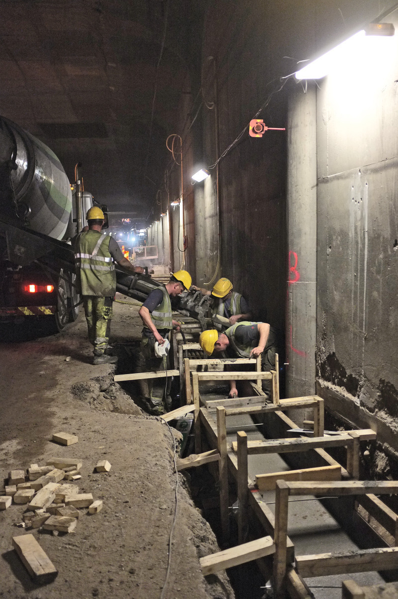
• Casted cable channel on both sides (Fig. 1)
• Sewage works
• Installation of pre-cast concrete barrier elements
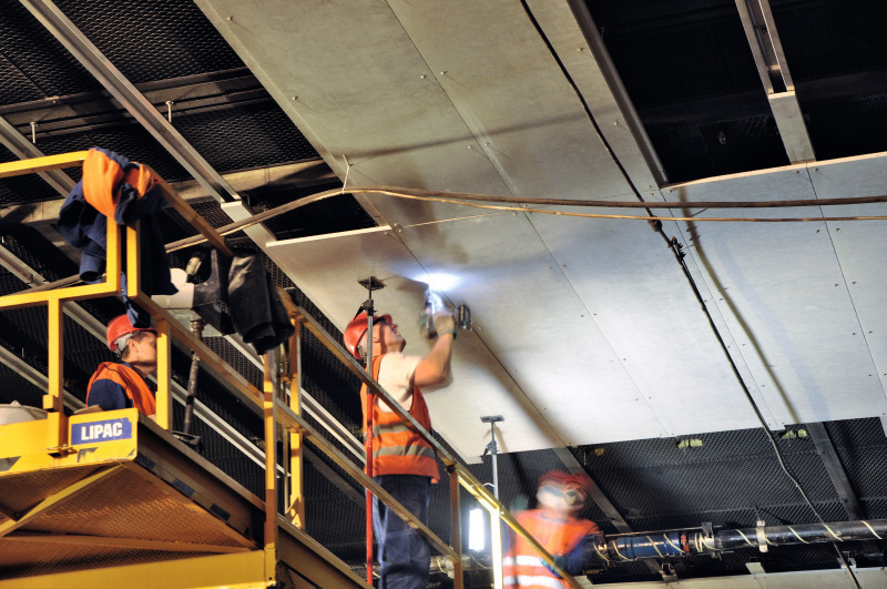
• Fire protection of the tunnel ceiling
• Reinstallation of noise reduction ceiling
• New electrical installation
• New ventilation
• Wall coating with photo-catalytic coating for NOx and Ozon reduction
• New top layer of asphalt
The principe of the hydro demolition, barrier elements and fire protection is described in detail.
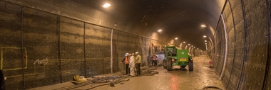
Hydro-demolition and shotcrete
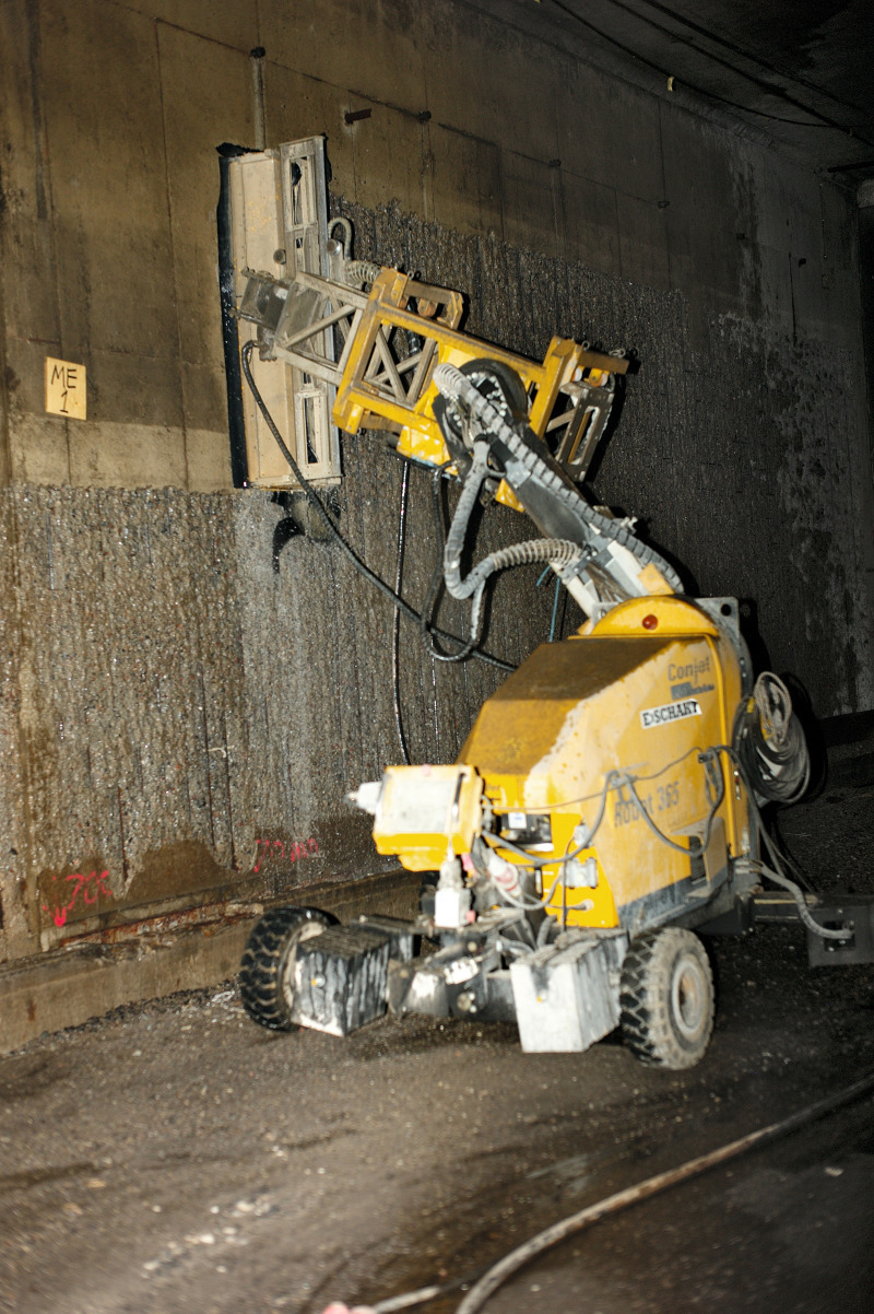
The concrete walls in the tunnel had been damaged due to intrusion of chlorides from road salt and carbon dioxide emissions caused by the traffic in the tunnel. It was known that the intrusion of harmful chemicals had reached to the reinforcement in the walls. The damages applied to the lower parts of the wall in general less than a meter above road level with a few places where the full height of the wall was damaged. In order to repair and asses the damages, particularly to the reinforcement in the wall structures, the surface concrete was removed using hydro-demolition to a depth of 70 to 100 mm. This uncovered the reinforcement and corroded bars could be removed and changed. However the damage to the reinforcement was much less than expected and very little reinforcement had to be replaced.
After necessary repairs the wall and reinforcement was sprayed with shotcrete until satisfactory cover of the reinforcement was achieved (Fig. 2).
Precast barrier elements
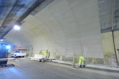
In order to protect the wall structure from future damages from road salt and carbon dioxide, precast concrete elements (barrier elements) were installed along the walls on both sides. The upper line of the elements is situated about 1.7 m above the road level. All the elements were cast in steel moulds and reinforced with stainless steel bars, EN 1.4362, with very high corrosion resistance. The thickness of the elements at the bottom is 180 mm and the standard length of an element is 3.8 m.
The elements were installed on stainless steel bolts, M20 and M24, at a distance of about 8 cm from the wall i.e. creating a gap between the back of the element and the wall. After installation of the elements the gap was filled with self compacting concrete and the top was closed with a sealant. The total number of elements installed were over 700. Finally the elements were treated with STO HG 200 to further protect from chloride intrusion.
By this installation a much longer way for salt and carbon dioxide intrusion to the structural reinforcement in the walls has been created. The system is designed for a lifetime of a minimum of 80 years (Fig. 3).
Fire protection
The fire protection upgrade based on a detailed analysis and planning of the existing tunnel and top structure. Due to the step by step construction of the tunnel there are 17 different cross sections from rock tunnel to precast and also pre- and post-stressed concrete slabs. On top of the tunnel are streets, yards, residential, commercial and public buildings.
The highest risk for the Söderleds Tunnel was defined as a fire scenario with a maximum temperature of 1200 °C for 60 minutes. The expected fire behaviour was closest to the German fire curve called ZTV-Ing (former RABT) but with an extension from 30 to 60 minutes fire before cooling phase of 110 minutes.
This versatile structure let the planning start with a structural analysis of the existing concrete quality, concrete cover, reinforcement and shape of the tunnel ceilings and walls. The first step was a numerical investigation of the spalling sensitive of the concrete. The high increase of the temperature, up to 1.200 °C in 5 minutes, and the maximum temperature of 1.200 °C determining the spalling effects mostly. The concrete properties were taken as:
• K40, compressive strength 28.8 MPa
• Aggregates: granite based maximum 32 mm
• water-cement ratio: 0,45 to 0,50
• moisture: 4 %
The results showed a high spalling risk for the ceiling areas with top structure as a combination of temperature development and bending stress, an medium risk in the ceiling area without top structure, like roads and yards and a low risk at the tunnel walls due to the expected lower temperature on the wall surface than a ceiling and lower bending stress. For the lower part of the wall the new pre-cast concrete elements were part of the fire protection as well.
A maximum concrete temperature for the areas with high spalling risk was defined as 380°C. The limitation of the temperature reduces the structural damage of the concrete and speed up any repair works after a fire scenario. Due to the different construction types of the ceiling slabs, different concrete covers and reinforcement types were used. So each section got it‘s own temperature limitation for the rebars. The maximum temperatures were defined between 260 and 290°C.
Based on this investigations the fire protection of the ceiling was designed and calculated with a fire protection shotcrete. The thicknesses variated between 25 and 60 mm to reach the different temperature levels at the concrete surface and reinforcement. The remaining risk for the unprotected tunnel walls and areas without top structure was evaluated as acceptable.
Due to the high amount of parallel works and logistics in the tunnel, an alternative solution for the fire protection was discussed with the joint venture, client and consultant to achieve a more flexible and environmental friendly method. Täby BrandskyddsTeknik AB and Fermacell GmbH worked out together an alternative solution with a cement based fire protection board, named Aestuver T. The system is based on a “dry-lining” installation with only one board thickness for all tunnel areas. The mounting can be done from scissor and beam lifts, with a high flexibility to change installation places in a short time and keeping always a traffic line open.
The approval of the system was based on several fire and durability tests and thermal calculations. The thermal calculation gives the chance to adopt the results from the fire test to the specific project requirements and geometry. In the first step a comparative calculation with the “real” fire test was done to proof and adopt the parameters of the fire protection boards and the software. In the second step the thermal gradients for the maximum temperatures for flat ceilings and beams were calculated.
The results showed that a fire protection with the 20 mm board on 10 mm joint backing strips for the flat concrete and concrete beams were sufficient to full-fill all the passive fire protection requirements of the project. For the areas with stressed reinforcement and TT-elements a suspended ceiling with stainless steel profiles and 20 mm fire protection boards on 20 mm backing strips were choosen as preferred system. The higher thickness of the backing strip gives a better protection to the stainless steel subframe and reduces the thermal expansion and bending.
In the first weeks of the refurbishment the discussion about a fire protection of the middle risk (unprotected) areas come up. Täby Brandskyddsteknik and NSA could convince the client to do the same fire protection level all over the tunnel ceiling. In the clients view it was more than worth to spend extra money during the refurbishment to eliminate the risk for a costly and time consuming refurbishment after a fire in an unprotected area. As well the good progress of the installation and the good aesthetic look helped on the decision.
Fire protection system of flat concrete and precast beams
The existing flat concrete was in a relative good condition for the installation of fire protection boards. The surface was mostly even and only small damages. The reinforcement depth was between 40 and 50 mm. With these conditions a 20 mm fire protection board was mounted on 10 mm backing strips with a width of 100 mm. The strips protects the joints and makes the board surface more regular. As a fixing Täby Brandskyddsteknik choose the Fischer nail anchor FNA II 6 x 30/30 with pan head. A drilling through the boards and backing strips 40 mm into the concrete and a fast setting of the anchor with a pneumatic hammer and tool allowed a fast installation. The remaining small joints to the tunnel walls were protected by a vertical board strip mounted an the wall.
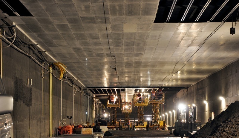
Precast and stressed ceiling
The suspended system was used in 2 different areas (Fig. 4). First approx. 200 m of the tunnel ceiling was built by precast prestressed TT-elements. Under the elements a noise reduction ceiling was installed to protect the building above from traffic noise. The fire protection should be suspended under the noise reduction to keep the protection effect. Luckily the TT-cassettes had a precast channel which could be used with a hammer head screw to hang down the profiles. Only a small hole need to be cut in the noise reduction elements made of steel net and mineral wool. For the support TBT designed an Omega profile for easy installation, fast connection. As well the profile gives some flexibility between each fire protection board. So small structural movement can taken without stressing or damaging the fire protection boards. The profiles hanging in the longitudinal direction of the tunnel with 625 mm distance. The boards and a 20 mm backing were fixed in the profiles with self-drilling screws. All steel parts had to be stainless steel A4.
The second area was located in the end of the tunnel under a hotel complex. Precast and post-stressed TT-elements are laying on walls and beams to carry a hotel on top. Due to the stressed reinforcement a drilling in the first 200 mm of the elements wasn‘t allowed. So a bracket was used to get the profiles suspended from the sided of the element beams. The profiles and boards were used similar to the first area (Fig. 6).
Installation
The first step into a successful installation with all the parallel works and traffic in the tunnel was the detailed planning. The JV used a system called visual planning. The idea is to bring all the involved parties once or twice a week together on a table. Everybody confirm the complete work from the previous week and shows the detailed planning for the current week. As well an overview about the coming work is given as an indication. All actions are put together on notes with area and date on a map, public to all parties.
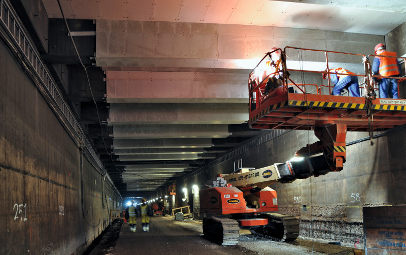
To keep the full flexibility for the installation, mainly scissor lifts and beam lifts were used. Totally up to 7 teams by 3 workers installed the fire protection boards from the lifts. The ground staff, 3 to 4 workers were taking care about the logistics and material preparations.
This system allowed to plan the installation according the work space in the tunnel. During the project the installation took place from 2 to 5 places at the same time in the tunnel. Not seldom the working area needed to be changed due to other works. Due to the casting of cable channels on both sides a trench needs to go along the tunnel walls with a width of 1.000 mm. The side areas were difficult to reach from scissor lifts and it was impossible to go ahead of the digging. A special beam lift with a capacity of 1.000 kg were brought in from the Netherlands to access these areas. To keep the installation progress equally between middle and sides the beam lift was running in 2- and 3-shift-system. The increase of the fire protection area from 15.000 to 22.000 m2 during the project wasn‘t a problem to include in the project time schedule. With the full working capacity up to 450 m2 were installed in 24 hours.
Of course a refurbishment is never without any surprises. Many different small solutions needed to be developed during the project. The location of all parties in the same office allowed a very efficient communication. The technical issues were solved in cooperation and practice-oriented based on the suggestions from TBT. So for example a ventilation duct from an asian restaurant crossing the tunnel ceiling in the exit to Södermalm, hidden under a removed noise reduction ceiling and some old wooden constructions were found in the tunnel (Fig. 7).
Conclusion
All in all the project became successful for all involved parties. The time and cost schedule was kept and the result was very satisfying for the client and the users. The good cooperation and communication between the parties and the high technical knowledge were key factors for the success.