EPBM Excavations of Prague Subway “Metro V.A.”

The Metro V.A. extension included 4.8 km of twin tunnels bored by 2 Earth Pressure Balance Machines (EPBMs), and 1.3 km section including mined double track tunnel. The article focuses on the experience with EPBM excavations, and provides a brief description of the stations and mined tunnels.
The construction of Metro V.A., the fifth extension of line A, started in April 2010. It will add to operation 4 new stations and 6.1 km of tunnels to the existing Prague subway network by the end of 2014. Prague subway, whose origin dates back to 1967, has 59 km of operated alignment tracks, which are mostly underground, and 57 mostly mined underground stations. The Metro V.A. extension included 4.8 km of twin tunnels bored by 2 Earth Pressure Balance Machines (EPBMs), and 1.3 km section including mined double track tunnel.
1 Project
Metro V.A. was the first phase of the 2 phase project to build the subway connection to the Vaclav Havel International Airport. The funds of 750 million Euro for the 5 year project of the first phase were provided by the owner Dopravni Podnik Praha a.s. (DPP), out of which 40 % could be provided by the European Union. The project was supervised by the Inzenyring Dopravnich Staveb a.s. (IDS), and designed by the Metroprojekt Praha a.s.
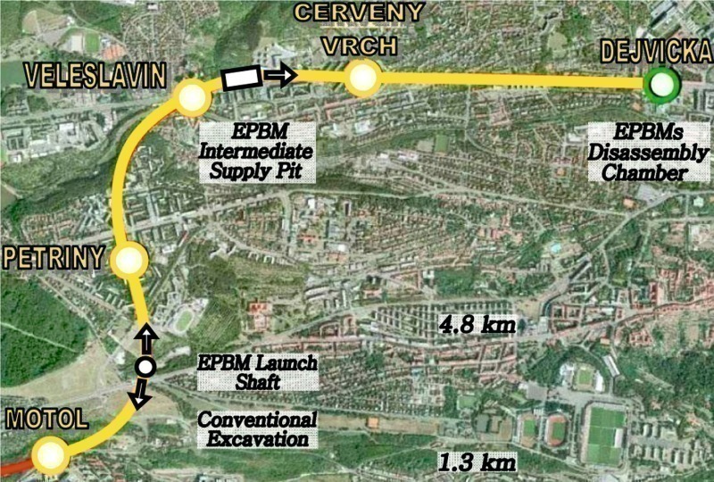
The construction works including the rail installation have been won for the price of 545 million Euro by the Joint Venture of the Metrostav a.s. and the Hochtief CZ a.s. companies, which divided the amount of the works in the ratio of 60 %, and 40 %, respectively. The Metrostav Company was responsible for building 4.8 km of twin tunnels, and 2 underground stations Petriny, and Veleslavin (Veleslavin was built by the daughter company Subterrac a.s.), while the Hochtief CZ Company accounted for the 1.3 km double track tunnels including the open cut Motol Station, and the mined Cerveny Vrch Station (Fig. 1).
1.1 Schedule
The 5 year project schedule dictated that the construction works be completed in 4 years by the end of 2013 to allow time for the technology installation and the test operation. To comply with the 4 year construction schedule the construction of the stations and the tunnels had to be planned to run in parallel and independently as much as possible. That could seem a difficult task, since the 4.8 km alignment of the EPBM twin tunnels was passing through 3 underground stations. The station excavations would obstruct the EPBM excavations, and vice versa, the stations final linings would not be finished before the EPBM operations cleared the stations. The avoid potential construction site interferences and delays, separate access pits, shafts and adits had to be built for the stations and the tunnels, plus an intermediate access shaft was placed in the middle of the 4.8 km for relocating the supply and logistic operations of the EPBMs to allow an early start for completion of the 2 underground stations Petriny and Veleslavin.
Thereby, the EPBM excavations got on a critical path, which commanded the twin tubes to be completed in a year and a half from the date the machines were assembled at the launch shaft (mid of 2011) until they broke through in the Dejvicka disassembly chamber (end of 2012). The design and selection of EPBM technology and logistics were therefore focused on ensuring continuous excavation operations, which would permit the machines to achieve an average performance of 12 to 16 m/day for the entire 4.8 km alignment. For that purpose the Metrostav Company opted for the two-component grout system, which pumped the fill grout from the surface to the tunnel; conveyor belts, which transported muck from the tunnel to the surface; and rubber wheeled Multi Service Vehicles (MSV) for the segments transport. All the 3 technology components reduced materials handling at the access shafts, and made the logistics simpler, therefore less prone to delays.
Since the EPBM walks and the re-starts represented significant interruptions in the EPBM drives, the technology also included a prefabricated unitized system allowing a quick assembly of the cradle supports and the bracing frames inside the underground stations and the pits.
Although several challenges were encountered during the EPBM operations, the first time experience of the Metrostav Company with the modern EPBM technology was successful, and the EPBM excavations were completed on the schedule thanks to the technical site support and the innovative technologies.
1.2 Alignment
The Metro V.A. extension will add an additional capacity of 45.000 passengers per day to the existing Prague subway ridership of 1.3 million of passengers per day. To comply with the planned capacity, the 100 m station platforms accommodated 5 wagon trains, and the alignment was designed for a train speed of 80 km/h with minimum headway of 90 seconds.
Three underground stations along the twin tubes alignment were designed with center platforms 10 to 12 m wide, while the Motol station, as part of the double track tunnel alignment, included 2 side platforms 2 x 5 m wide. The minimum horizontal curve was 640 m, and the vertical gradient 3.95 %.
For better passenger circulation the stations were kept as shallow as possible. Considering the minimum rock cover the resulting stations depths ranged from 20 to 40 m. Ventilation shafts, rooms, and technological objects were built at each station, and the distance between the twin tunnels crosspassages was about 200 m.
1.3 Geology
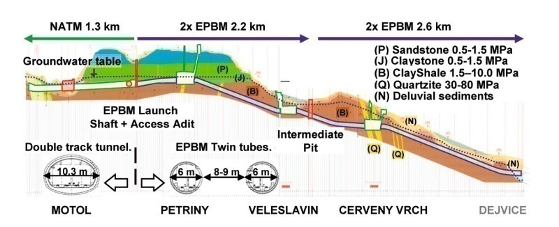
Major portion of the alignment was situated in the clayshale bed-
rock (Fig. 2). At the launch shaft, about 0.7 km of the alignment was intersected by the waterbearing sandstone sealed by the clayshale layer at the bottom. Shallow alignment portions were intersected by deluvial sediments and by weathered clayshale bedrock horizont classified usually as clayey sand or clayey gravel.
The bedrock layers were characterized by uniaxial compressive strengths of undisturbed intact rock samples in the range of 5.0 to 15 MPa with some in the range of 15 to 50 MPa. In reality the majority of encountered rocks had the strength in the range of 0.5 to 1.5 MPa. The deformation modulus of the rock mass including 3 sets of discontinuities was estimated between 25 GPa and 300 GPa. In contrary to the tender documents, which anticipated drill and blast operations, the excavation in the soft ground was possible with mechanical means of excavators and diggers, yet, the unweathered bedrock provided vertically stable excavation face, which allowed the major portion of the alignment to be excavated in the EPBM open mode.
The design intention was to keep the excavations as much as possible under the cover of the bedrock layers, which provided sufficiently stable face, roof and bottom stability for the time of support installation in the mined stations and the tunnels. Besides observing the stability, the soft ground deformations were restricted by the project surface settlement criteria, which were established for the EPBM excavations by the maximum differential settlement of 1/800, and by the maximum settlement of 10 mm.
The maximum groundwater table elevation above the tunnels crown was 28 m. Clayshales and claystones were typically impervious, however in weathered zones, shears, faults, or especially when intersected by blocky quartzite intrusions the ground water inflows could reach 1 to 5 l/sec. High groundwater inflows were experienced in the waterbearing sandstone, where the inflows locally ranged from 5 to 10 l/min.
2 Conventional
Tunnelling
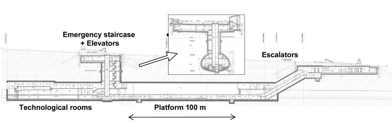
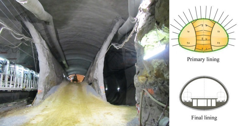
Passenger safety and transportation regulations required that the stations had 3 accesses: a) escalators, b) elevators, and c) emergency exit staircase (Fig. 3). By including the technological rooms the stations lengths varied from 130 to 220 m, and for the construction were divided into several dilation units.
The final lining of the underground stations was a cast in place concrete C 30/37 built in thickness 400 mm (Veleslavin), and 600 mm (Petriny, Cerveny Vrch) protected by undrained waterproofing membrane. The waterproofing of the single-vault stations Petriny and Cerveny vrch implemented PVC sheets covering the arched station walls, the bulkheads including the junction with the EPBM tunnels adopted sprayed membrane. In the binocular (three-vault) Veleslavin Station the sprayed waterproofing membrane was adopted for the entire station because the geometry of the 3 arches and the pillars resulted in a complicated detailing for installing the PVC sheets.
The primary linings of the underground stations were sprayed concrete C 25/30 with thickness of 300 mm (Veleslavin) and 400 mm (Petriny, Cerveny Vrch).
2.1 Petriny Station
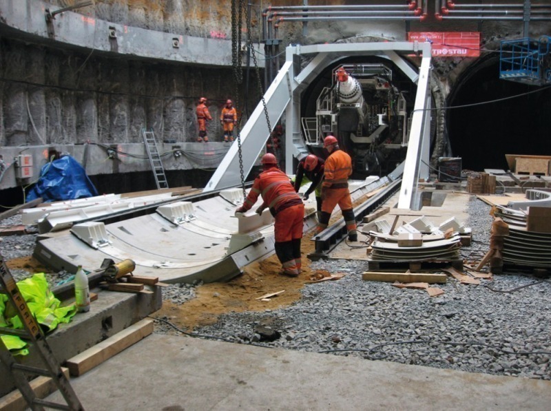
The original plan for the Petriny Station was to access the station excavation through the EPBM tunnels. That would however put the station on the critical path in the construction schedule since the excavation would have to wait till the EPBMs were manufactured, assembled, passed through the station, and completed the operations by reaching the intermediate pit. To minimize the risk of project delay that could be caused by postponing the start of Petriny Station excavation, the Metrostav Company realized a 300 m long access adit, which allowed excavating the station in advance of the EPBMs, and completing it in parallel with the EPBM operations.
Petriny station excavation profile of 265 m3 with the span of 22 m and height of 15.5 m was situated in the mixed face of soft waterbearing sandstone (upper 2/3) and claystone (lower 1/3). The soft claystone in places interlaced with thin coal beds would not provide sufficient bearing capacity for the station bottom therefore the station excavation implemented the twin side-wall drift method, which first built the side drifts to support the station arch (Fig. 4). The excavation face was stable and no additional measures were required to stabilize the face, while the walls were supported by the primary lining with the grouted bolts.
By the time the 2 side-drifts were completed and the center drift was still under excavation the EPBMs arrived in the station and were walked through the side-drifts separated from the center drift by the temporary side-walls (Fig. 4). Under their protection the center drift excavation was completed and the invert was closed while the EPBM operations were still running in the side-drifts. After the EPBM logistics were relocated to the intermediate supply pit, the temporary side-walls were demolished from a gravel ramp.
For the EPBM breakthrough, the bulkhead of the station had to be modified, because it was formed by the curved primary lining of the station access adit bifurcating into the side-drifts. Boring through them could lead to stability problems. Therefore 10 m of the bifurcated adits were filled with the light concrete which at the same time formed a vertical wall for the EPBM
breakthrough (Fig. 5).
The 15.5 m height of the station made the structure rise above the groundwater table, and could create a dam for the groundwater flow in the waterbearing sand-
stones. To minimize negative impact on the environment, drainage channels were installed on the exterior of the station liner, which allowed the groundwater to flow under the station, and the station did not intercept the groundwater springs.
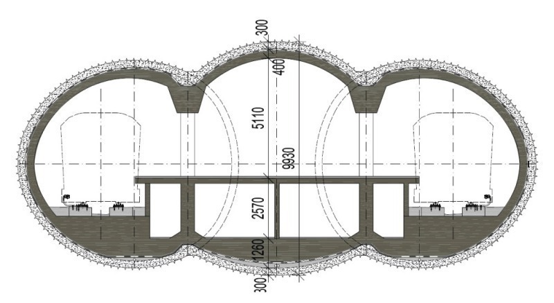
2.2 Veleslavin Station
The Veleslavin Station shallow depth required a binocular structure design, which thanks to the low construction height of the 3 vaults minimized the excavation exposure to the upper deluvial sediments (Fig. 6).
The construction sequence proceeded first with the side tunnels, which were excavated, and supported with shotcrete lining. After the EPBMs were walked through the side tunnels, and the EPBM logistics were relocated to the intermediate pit, the side tunnels were waterproofed with the sprayed membrane, and furnished with the cast-in-place final lining, and the concrete pillars to support the future arch of the middle tunnel. After the completion of the 2 side tunnels, the middle tunnel was excavated and supported with the primary and final lining and also protected with the sprayed waterproofing.
In spite of the low height of the binocular station the crown excavations were exposed to the variable profile of weathered clayshale bedrock and locally reached the upper sediments. Since the excavation took place under 2 to 5 m of groundwater table, the roof stability had to be protected by a canopy of 6 m long chemically grouted IBO 32 mm bolts and the face was stabilized by chemically grouted 8 m fibre-glass bolts.
2.3 Cerveny Vrch Station
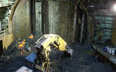
The Cerveny Vrch Station excavation of the 225 m2 profile, 20 m span, and 15 m height in weathered shale and blocky quartzite required the side-wall drift method to mitigate ground settlements and potential ground instability at nearby residential structures.
The additional measures including short excavation round, pre-grouting, and bolt canopy necessary to stabilize the rock in advance of the excavation, slowed the advance rate and did not allow to complete the station excavation before the EPBMs arrival. After the machines walked through the side drifts and resumed excavations on the other end of the station, the center drift excavation continued along with the EPBM operations. In contrast to Petriny Station, the side walls were demolished as the center drift excavation progressed. To assure a safe working environment for the EPBM workers, the Hochtief CZ Company installed curved steel plate barriers to stop demolished concrete from flying into the side drifts.
In the end the excavations of Cerveny Vrch Station were completed in parallel with the EPBM operations.
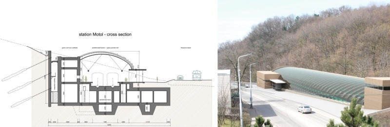
2.4 Motol Station
The Motol Station was designed in an open pit cut in a slope, whose geology composed of sandstone blocks embedded in clayshale base.
Retaining walls made of Milan diaphragm concrete walls and anchored by the permanent cable bolts, stabilized the excavation against activating potential slope movements (Fig. 7).
The permanent cable bolts were equipped with devices for monitoring the cable tension, and the space left between the station and the wall served for the maintenance and the bolts re-tensioning (Fig. 7).
The station was built as two-storey structure. The hallways below the platform were built at the same level as the street underpasses to provide a convenient transfer of the passengers to the adjacent Motol Hospital.
The arched roof was made out of glass panels to preserve day light illumination on the platform (Fig. 7). The panels were supported by the steel reinforced concrete beams, which represented a difficult structure both for the production and for the installation, since the profiles and the lengths of the arched beams varied as the height of the wall along the slope was increasing. To avoid procuring many different formworks, and unify the beams the station wall facing the slope was slightly curved.
The glass panels were designed in compliance with the fire safety requirements, they reduced daylight glare for the train operators, and assured pleasant interior temperatures in all seasonal weather conditions.
2.5 Double-track Tunnels
Double-track tunnels were mined conventionally by heading and benching method along a 1.3 km portion of the alignment, which included Motol Station, and also a short mined tunnel for storage tracks.
Excavation profile of 65 m2 with span of 10.5 m, and height of 7.5 m in the clayshale bedrock was supported by the shotcrete liner of C 25/20 concrete with 250 mm thickness, bolts, and the closed invert.
Weak and discontinuous clayshales were mined by impact hammer and excavators, yet, the rock excavation face was stable. However, when exposed to air and especially in the presence of the ground water inflows the shale rock quickly disintegrated. The clayshale exposed surface quickly gained a soft clay consistency, which reduced the friction angle to zero between the rock blocks. To prevent the weathering of clayshale and provide a firm base for the tracks the invert was closed systematically in a distance of 15 to 150 m behind the heading.
The final lining was cast in place concrete of C 30/37 with a thickness of 400 mm, which was protected with the un-
drained waterproofing of PVC sheet membrane.
3 EPBM Tunnelling
Two fundamental features of the EPBM technology decided that it was selected for the excavation of the two 6 m diameter tunnels along the alignment stretch of 4.8 km: 1) high excavation speed, and 2) positive face pressure to stabilize the ground and minimize the settlements.
The project could provide only a limited number of construction sites in the densely populated urban environment. For the twin tubes excavation 2 access sites were established: the launch shaft, and the intermediate pit, which divided the alignment into 2.2 km and the 2.6 km sections. With respect to the tunnel lengths the project schedule defined that the excavations had to comply with the average speed of 12 m/day or 360 m/month (24 hours, 30 days).
The logistics were designed to allow the simultaneous EPBMs operations achieving maximum speeds of 30 m/day, which made the requirement of average speed of 12 m/day no difficult task. In reality, the best advance rates of 630 m/month, and 36 m/day were achieved.
The tunnels were mostly under a sufficient cover of the clayshale bedrock, yet there were structures along the alignment, which necessitated protection against ground settlements. To comply with the project settlement criteria of maximum 10 mm surface settlement, and maximum differential settlement of 1/800, the EPBMs excavated in closed mode with the face pressure in the range of 1.4 to 2.4 bar. With only few exceptions the ground deformation generated by the EPBM excavations complied with the settlement criteria.
3.1 EPBM Technology
The two EPBMs S609 and S610 were procured from the Herrenknecht. The machines technical parameters (Table 1), respected given geological conditions, and several technological features were added to the EPBM design: Metrostav requested a bentonite pressure injection system for supporting the ground around the shield and the face to avoid generation of excessive ground loads on the machines during the EPBM long standstills; wear resistant material of chromium carbide was ordered for the cutterhead and the screw conveyor protection in the highly abrasive sandstones with high quartzite content of more than 85 % and Cerchar abrasiveness of 4.5 that were encountered in the first 500 m of excavation; the cutterhead opening ratio was increased up to 30 % to minimize the potential of cutterhead clogging by clayey muck expected in the deluvial sediments and weathered clayshale rock, where encountering boulders was not expected.
3.2 Cutters
The cutterheads were factory fitted with seventeen 17“ double disk cutters and four 17“ single gauge disk cutters, however during the EPBM site assembly the disks were exchanged for rippers in response to unexpectedly weak clayshale, sandstone and claystone rocks with Uniaxial Compressive Strength (UCS) of 0.5 to 1.5 MPa, which were encountered during the station adit excavation. The advantage of the rippers was smaller price and less weight for manipulation. The rippers performed well, and their consumption rate was similar to disc cutters. In abrasive sandstones the consumption rate was one gauge cutter per 70 m of excavation. The comparison between performances of the gauge cutters was made possible by having the ripper cutterhead on one machine including the 4 gauge cutters while the other machine retained the disk cutters for the gauge cutters. The original double bit rippers were later replaced by single bit rippers to reduce the cutterhead torque, however, at the first encounter with the thin but hard and blocky quartzite inclusions (UCS of 80 MPa) in the clayshale, the rippers were damaged. Since then the disk cutters were used. Compared to sandstones, in the clayshales the consumption rate of the gauge cutters was lower: one cutter per 250 m. The consumption rate was reduced even lower with the use of 18“ disk cutters, which resulted in consumption of one cutter per 350 m.
3.3 Logistics
All the logistics of the materials transport in and out of the tunnel including conveyor belts for the muck, batching plant, pumps and piping for the grout fill, and MSV vehicles for the segments transport were designed to enable the EPBMs to work in the full capacity of 30 m/day (20 rings/day).
The use of conveyor belts increased the work safety and continuity of the transport operations especially in the circular launch shaft of 22 m in diameter, where handling of the muck trains of the 2 simultaneous EPBM operations would be slow and dangerous. With the conveyor belts transporting the muck directly to the surface, only one tower crane was required for loading the segments on MSVs, in addition, the segment transport gained independence from the muck transport, which made savings in using only 2 MSVs per tunnel. At the launch shaft, the joint conveyor belt (800 mm wide) for both EPBMs transported the muck through the tunnel adit to the surface deposit. At the intermediate shaft, the 2 EPBM conveyor belts (650 mm) transported the muck from the pit bottom to the surface in an inclination of 17°.
MSV vehicles were also an important addition to the work safety thanks to their short breaking distance and good manoeuverability of independent 2 axle steering, which was important in tight working spaces of the underground. The MSVs had output of 147 kW, capacity of 17.5 t , and maximum speed of 16 km/h.
3.4 Segmental Lining
The segments were prefabricated by the Doprastav a.s. in their Slovakian plant, which in the cold production rate was able to output 9 rings/day. Nine stationary formwork sets equipped with external vibrators were served by a crane transporting concrete in containers. The concrete hardened for 16 hours in the ambient temperature of the production hall without any additional heating except for winter time when the hall was heated up to 16° Celsius. Reinforcement cages were welded from single steel bars.
The 5+1 ring configuration of the universal rings with 15 mm taper on both sides (total 30 mm) accommodated conveniently the minimum horizontal curvature of 640 m with a reserve for a 300 m recovery radius. The inside diameter was 5.3 m, the thickness 250 mm, and the width 1.5 m.
The contact at the circumferential joint between the rings was cushioned by the hard board plates, and fastened by 16 screw connections in correspondence to 16 thrust rams, which resulted in 16 available positions of the key segment in the ring assembly. The longitudinal joints of the key segment included guiding rods, and the segments were waterproofed with the neoprene gaskets
Phoenix M 385 96.
The amount of steel reinforcement of 105 kg/m3 represented the reinforcement ratio of 0.5 % including both compression and tension bars.
Measures were taken to avoid chipping of the segment edges by keeping the ram plates at a distance bigger than 50 mm from the segments edges, which corresponded to the minimum 50 mm cover of the steel reinforcement prescribed by fire resistance criteria. The ram plates contact areas were optimized for the thrust pressures not to exceed 23 MPa under the maximum EPBM ram force of 2432 kN (hydraulic pressure of 320 bar in the cylinders).
Attention was paid to the potential of the concrete bursting induced by tensional stresses generated under the thrust plates of the EPBM rams. The impact of the ram loading was modeled in a 3 dimensional numerical model including an explicit model of the steel reinforcement cage, and was confirmed by an experimental laboratory testing. Both models numerical and experimental showed more than sufficient segments concrete resistance to bursting, as their results concurrently reported appearance of the first negligible cracks of 0.01 mm at the 100 % pressure of the maximum design thrust (2432 kN), appearance of the significant cracks of 0.15 mm at the 200 to 210 % pressure, and cracks running through the segment 250 mm width at 220 to 230 % of the maximum design thrust. Segment collapse was achieved at the 250 to 330 %.
4 EPBM Tunnelling Challenges
Design and preparation works during the EPBM pre-production, production and assembly phases, which included staff training of the future EPBM operators and technical supervisors contributed to timely start and finish of the EPBM excavations. Few challenges that were encountered during the drives and that could hinder the continuous advances were effectively tackled by the site workers, which indicated a successful adoption of the EPBM technology.
4.1 EPBM Impact on Segments
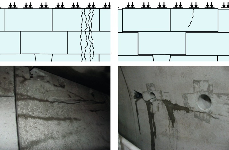
The first segmental rings installed immediately after launching the EPBMs contained cracks, which would not be unusual for any TBM launch, however the cracks kept appearing also in the rings during advanced excavations, in which the segments were already properly embedded in the grout fill. The segments cracking got a lot of attention, which led to an investigation of the cracks origin.
Two types of the cracks were distinguished: a) Cluster cracks – a group of up to 4 cracks, which were running across the full 1.5 m segment width, and were persistently appearing at one location of the ring for a distance of tens of tunnel meters, b) Random single cracks – a single crack in the middle of the segment (Fig. 8).
The crack types had in common several features that could point out their origin: the hairline thickness of less than 1 mm; none or minimum groundwater leak; the inception of the cracks within the tailskin, while the ring was still being pushed by the thrust rams; the thrust ram forces operating at less than 100 bar (less than one third of the maximum design pressure); the cracks orientation in parallel with the tunnel longitudinal axis.
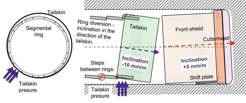
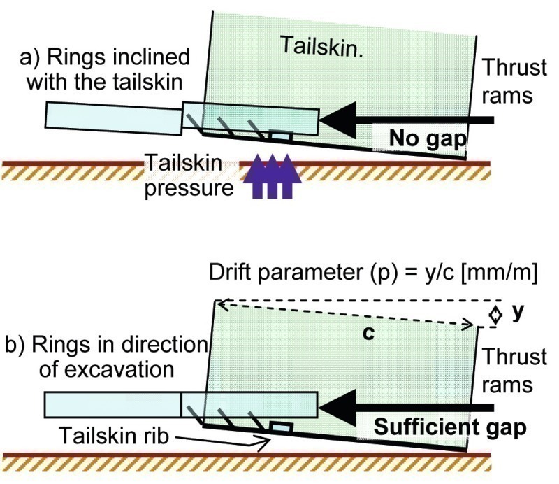
The investigation revealed that the source of the cluster cracks was the inward bending of the ring in transverse section, which was induced by the contact pressure of the tailskin (Fig. 9). When bended the cracks opened on the inside surface of the segment, then after leaving the tailskin the cracks closed. For the tailskin envelope to push on the ring, the 30 mm tolerance gap between the tailskin and the ring was exceeded, which was achieved by a combination of several factors: deformation of the tailskin; inclination of the tailskin (tailskin drift); ring deformation (elliptical ovalization); diversion of the ring from the excavated alignment (wrong selection of the ring orientation). However, none of those factors alone could lead to such a tight contact with the tailskin to crack the segments, but their combination could, as it was observed several times during excavation, when cracked rings stretched over a 70 m distance.
The solution was sought in eliminating the segment diversion, which would also reduce the impact of tailskin inclination. The VMT GmbH facilitated an input of a “drift” parameter into the segment selection procedure, which determined the key stone orientation for the next ring installation. The drift parameter corrected the ring position by making it parallel with the excavated alignment rather than with the inclined tailskin (Fig. 10).
The single cracks were typically originated from the niche of the screw connector in the middle of the segment, and extended diagonally or parallel but seldom reaching across the full 1.5 m width of the segment.
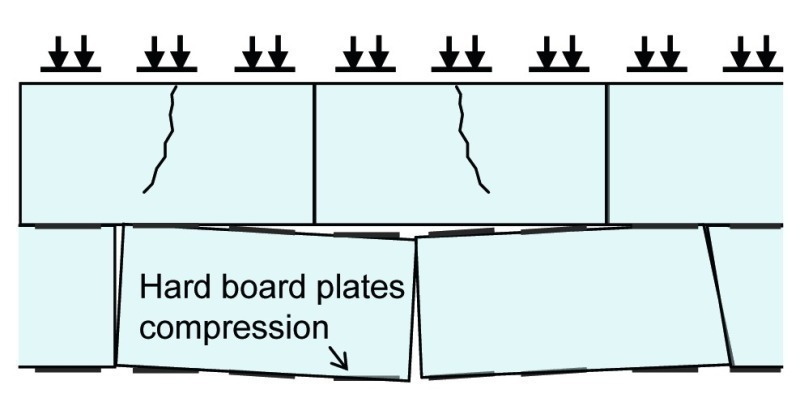
The source of the random cracks was the longitudinal bending of the segments, which resulted from an uneven circumferential joint plane support of the previous ring caused by non-uniform compression of the contact hard board plates (Fig. 11).
Although each ring assembly was sufficiently precise with the segment edges well aligned, the differential loading of the 5 ram groups led to the non-uniform compression of the hard board plates during the excavation cycle.
Segments that were not supported along the entire length became typically bended by the grip of the 3 thrust plates acting on one segment, which consequentially cracked the segment usually in the middle and with the crack running open through the entire segment thickness of 250 mm.
The unevenness of the rings was minimized by replacing the compressible 3 mm hard-board plates by thinner 1 mm hardened PVC plates.
4.2 Walks and Starts in Underground Stations
Three underground stations, one intermediate open pit, and one underground cavern for ventilation room represented an interruption for the EPBM excavations.
The 2 EPBMs had to walk 5 times through those underground spaces and had to be restarted 5 times to resume excavations.
Inventing a system of cradle supports, and designing a bracing frame for tight underground space which would be reusable, economic, flexible to modifications, and quick to assemble, was a challenge.
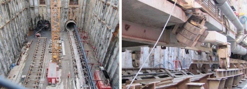
In compliance with those specifications, the site engineers designed a set of prefabricated and unitized steel supports, which could be universally used to support both the 6 m diameter shield, and the wheeled gantries. After the EPBM passed through the station the supports were dismantled and were re-used in the next station. The steel cradle was quick to assemble and disassemble, and easy to adjust to required directions and shapes (Fig. 12).
For the initial EPBM start from the launch shaft a massive beam frame was procured from Herrenknecht (Fig. 13). The same frame was used again in the intermediate pit for the re-start of both EPBMs, however the frame would not fit in the underground station drifts, and could not be assembled behind the shield since most of the space was occupied by the EPBM.
A suitable bracing would be the one whose major portion could be installed before the shield arrival, and by the time the shield was ready to bore, the bracing frame was capable of taking the load from the EPBM.
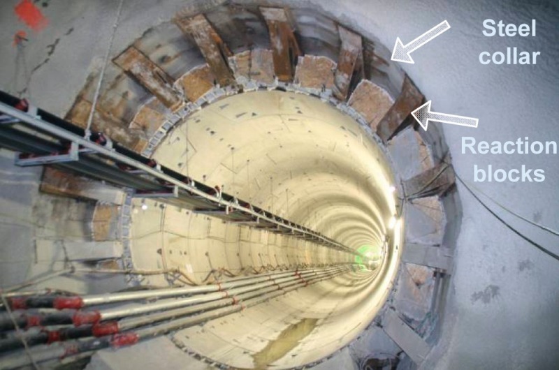
The selected bracing system consisted of a steel collar concreted and bolted into the primary lining at the neck of the 10 m launching chamber (Fig. 14). The collar was installed in an advance of the shield entering the chamber, which would leave sufficient time for the collar concrete to harden. Then behind the shield the steel reaction blocks were promptly welded onto the steel collar. The bracing system reduced the EPBM start time, however, provided much less reaction force than the beam frame, due to the low tensile bearing capacity of the lining and the rock. Low start force could be a major drawback if the force was required to prevent the machine from diving. The EPBMs were however equipped with the shift plate installed under the front shield, which safeguarded the bore against diving.
4.3 Two-Component Grouting
The decision to adopt the two-component grouting system for the EPBM excavations was based on the presumed minimum maintenance for cleaning the grout pipes, which relied on the system ability to control the time of grout hardening.
Thanks to the composition of the grout, Component A, the grout remained liquid for minimum of 72 hours but after mixing it at the right time and at the right place with accelerator, Component B, it would set rapidly in its destination place, which was the space between the lining and the ground. Component A composed of 300 kg of cement, 35 kg of bentonite, 8 kg of plasticizer, and 811 kg of water in 1 m3 was mixed with the Component B, which was 7 % of sodium silicate.
In addition, the prolonged liquidity allowed the grout to be transported in the pipes from the surface batch plant directly to the EPBM tank, which minimized grout handling operations. Component B (accelerator) was transported in containers by MSV and transferred to the TBM tank by pumping.
The initial experience with the grout was however not as expected, the EPBM tailskin grout lines clogged and because of that the excavations suffered from delays caused by frequent cleaning of the lines.
At the beginning of excavations, the clogging could have been explained by the learning curve, and by the stop and go excavation progress due to sticky muck problems, which led to low grout flows, and to high potential of settling. Nonetheless, the problems with grout clogging were still persistent also after the machines achieved continuous excavation advance rates of 30 to 40 mm/min.
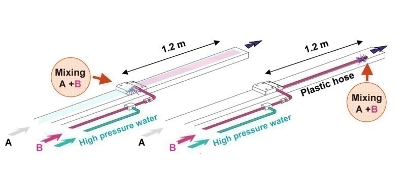
On average, the cleaning required minimum of 4 hours of tough hammering and drilling through hard grout in a frequency of every 2 days. The hard grout was deposited mainly in the 1.2 m long pipe, which transported the 2 mixed components from the mixing chamber to the tailskin end.
The situation improved significantly after a synthetic flexible hose was attached to the sodium silicate line, and extended from the mixing point in the midst of the tailskin to the tailskin end and out of the tailskin pipe (Fig. 15). By mixing the components outside the tailskin the potential for grout hardening inside the tailskin pipes was minimized. Nevertheless periodic maintenance was still required although the cleaning required much less effort and less time.
As the excavation progressed the two-component grouting confirmed other advantages that were associated with the system: immediate ring support, especially in high groundwater inflows, which did not wash out the grout mix after the gel time; minimal grout migration to the cutterhead in the open mode of excavation. To comply with the basic principle of the time control of the grout hardening, the grout recipe complied with the following strength parameters, the gel time of 6 to 10 sec, the 3 hour compressive strength of 0.06 to 0.3 MPa, and the 28 day compressive strength of 1.0 to 1.5 MPa.
4.4 Sticky Ground
The soft clayshale was a rock favourable for cutting, with low abrasion, and good penetrations under a low cutterhead thrust. However, the clay fines, which originated from the fragmentation of the clayshale, turned the muck into a sticky material, which clogged the cutterhead and stopped the EPBM. To free the cutterhead and transport the muck from the excavation front to the EPBM chamber, a balanced mix of foam and water had to be pumped to the cutterhead to suit given geology and underground water inflows.
In the planning stages the rock was expected to disintegrate into a cohesionless muck containing some fines and larger amount of hard rock chips produced by the disk cutters. Instead, the amount of clay fines was sufficient to make the muck a cohesive material when mixed with either the groundwater or with the foam.
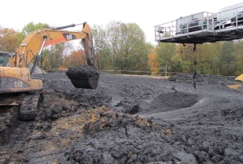
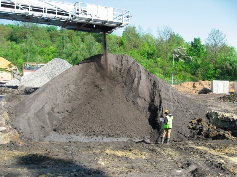
Thus the clayshale rock was continuously transformed into a mud, which required special deposit sites, while the excavations consumed large quantities of water (10 to 16 m3 per 1.5 m of advance) that was injected to the cutterhead contained in the foam, and separatly in an additional water channel. (Fig. 16).The reason for the muck stickiness and the cutterhead clogging was the clay fines content of more than 30 %, which was produced in the softer than expected rock, while the high water consumption was due to the clayshale natural water content of 5 to 7 %.
The initial EPBM drive of the first 75 m attempted to produce a “dry” cohesionless muck without foams and without additional water, which would eliminate the problems with handling a depositing the sticky muck (Fig. 17). However that was possible only in the rock with none or minimum ground water seepage. The effort to keep the muck dry failed with the variable groundwater ingress. The crews had to fight either the stiff clayey chunks overloading the screw conveyor or the muck slurry, which poured from the belt on the tunnel floor after the cutterhead was filled with groundwater during a standstill. Besides the screw conveyor clogging the excavation was also stopped when in front of the cutterhead the sticky muck formed a stiff cake at the cutterhead center, which prevented cutters penetration into the rock. A full stop to excavation took place when the muck finally plugged all the cutterhead openings, and no muck could be transported from the face. After 75 m of excavation it became clear that excavation in the “dry mode” was not possible in the given conditions. Therefore, the operators started to pump foams and additional water into the cutterhead.
A suitable mix of the foam and the additional water minimized the muck stickiness and produced a transportable plastic muck. The foam parameters and the water quantity had to be changed along with the geologic profile variations. Thus the operators had to pay attention to the muck consistency, and at the same time watched the cutterhead parameters. The average values characterizing the excavations with the disk cutters in the Metro V.A. clayshales were listed in Table 2.
5 Conclusion
In spite of the excavation interruptions by the stations, and in spite of the delays caused by the tuning of the EPBM drives in response to variable geologic conditions, the excavations were completed on time, which confirmed that the EPBM technology was well adopted for the Prague subway extension.
6 Acknowledgments
Thanks to the Metrostav workers, the site engineers, and the Herrenknecht, H&E, and VMT specialists who responded to the challenges of the EPBM drives and thus contributed to the EPBM excavations success.