High-Precision Segments: Prerequisite for a high-quality monocoque Tunnel
The precision of the segments produced are of great significance for a single-shell segment tunnel. This report devotes itself to the problems involved.
1 Starting Situation
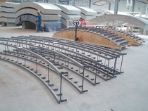
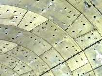
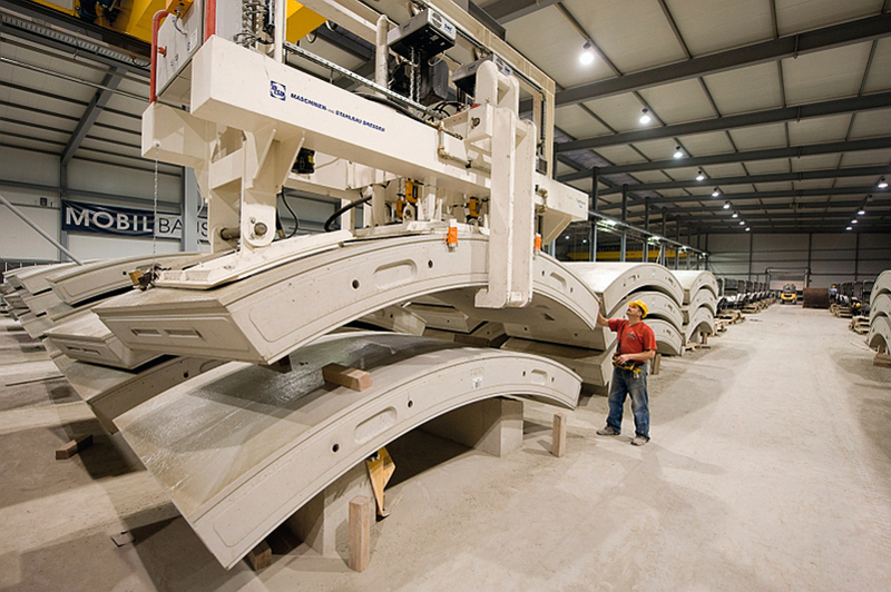
When producing single-shell tunnels excavated by shield, the dimensions of the segments – defined by the segment tolerances, are of enormous significance regarding the attainable quality (Fig. 1).
The dimensional accuracy influences the
a) stability and sustainability of the tunnel lining
b) the tunnel’s tightness against prevailing groundwater
c) acceptance of the prevailing ring loads (earth and water pressure, grouting pressures, support loads etc.) and
d) acceptance of the driving loads from the machine passage
The current permissible segment tolerances for Germany are presented in Guideline 853, Module 4005 Lining with Segments, of the Deutsche Bahn (DB Netze AG) for rail tunnels and in a Guideline from the German Highway Research Institute (BAST) for road tunnels, the ZTV-ING Part 5, Section 3 Shield Driving Methods.
There were no detailed requirements governing tolerances in Germany for producing segment elements until the DB Guideline DS 853.0019 “Planning, Constructing and Maintaining Rail Tunnels; Module Lining with Segments” was published in 1993. This Deutsche Bahn Guideline formed the basis for subsequent tolerance requirements in tenders for segments both for rail and road tunnels. The as from June 1, 2002 revised DS 853, subsequently known as Ril 853, largely took over these specifications, which until then constituted the valid parameters for planning tunnels made with segments. This also essentially applies to updates, currently with effect from March 1, 2011.
This report first examines the historical background of these regulations and their further development, findings obtained in practice and the significance of tolerance requirements for producing a qualitatively high-grade tunnel with a single shell. 2-shell tunnels with an outer shell made of segment elements and a subsequently produced inner shell are not dealt with. As the segments function as the outer shell, they require to fulfil fewer demands. The tightness requirements are fulfilled by the inner shell in the case of the 2-shell design principle.
2 Creation of Regulations for Segment Tolerances
The first version of the DS 853.0019 came about in 1993, before the first shield-excavated high-speed rail tunnel was planned.
Prior to this there were no special demands made on the production of the lining using reinforced concrete segments regarding the tolerances in tenders involving tunnels with segments – as e.g. for the urban transit tunnels in Cologne (1990) or Duisburg (1992).
In DS 853.0019 compiled in 1993 extremely “tough” criteria were deliberately established for selecting the tolerances so that a defect-free lining was assured and committing the contractor to come up with the highest possible quality. Should individual tolerances not be adhered to in practice, these could have been correspondingly dealt with between the client and contractor on the basis of static proof. This was also undertaken against the background that no pertinent experience was actually available with shield-driven monocoque rail tunnels and the regulation governing rail tunnels at the time only applied to tunnels with 2 shells. At the time, monocoque tunnel structures required to be approved individually (ZIE). Up till that point, no single-shell rail tunnels had been produced using segments.
Strict regulations at the tendering phase were also devised to counteract possible subsequent demands on the part of the contractor, should no defect-free lining be possible on account of excessive approved production accuracies thus necessitating the requirements to be subsequently raised.
Within the scope of German reunification the Finne Tunnel in the new federal states was the first project, whose tender was planned on the basis of the DS 853.0019. This tunnel was in fact the first high-speed rail tunnel to be produced with a single shell using segments. Owing to the omission of the inner shell, special demands were placed on the tunnel’s tightness. Against the background of these demands on tightness, the permissible production tolerances were formulated most strictly particularly in this field.
During the tendering phase for these first railway segment tunnel projects the strict specifications of DS 853.0019 were still further tightened according to declarations by the Deutsche Bahn after consulting with various advisory bodies based on the aspects mentioned previously. These stricter requirements applied to the segment arch length, the lining groove axis, the evenness of the longitudinal and annular joints, the permissible internal area as well as the maximal permissible assembly misalignment.
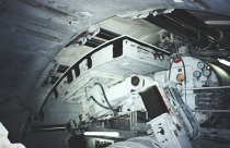
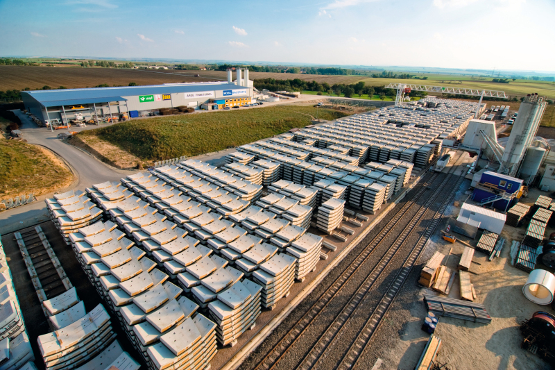
However accomplishment of the Finne Tunnel project was delayed and was actually produced at a later date between 2008 and 2010 (Fig. 2). In the interim, planning for the tunnel projects for the Berlin Mainline Route was carried out. On account of the comparable demands on the tunnel lining in Berlin the increased requirements on producing the segments for the Finne Tunnel were applied as the basis for the tendering procedure for the Berlin Mainline Tunnel project.
The good experience collected during the fulfilment of the Berlin Mainline Tunnel project prompted the Ingenieurbüro Maidl & Maidl, Bochum (IMM) in its capacity as tunnel designer to incorporate these enhanced demands in the tendering procedures for construction projects in conjunction with the goods traffic services for the Betuwe Route in the Netherlands, the Botlek and Sophia tunnels as well as the Pannerdensch Canal and for the subsequent Groene Hart and Randstad Rail, Statenwegtracé Tunnel projects.
In 1998, the Deutsche Bahn published a new version of Guideline DS 853.0019.
During the revision phase the permissible tolerances were adapted to the current state of the art for segment production. As can be discerned from Table 1 a number of specifications were omitted or reworded in the process.
When DS 853 was again revised in 2002, subsequently to be known as Ril 853, these specifications were taken over without being modified. The 2002 version is identical with the version introduced on January 1, 2006 regarding the tolerance demands and is thus referred to separately in Table 1.
The tolerance specifications for Ril 853 were based on angle specifications for the longitudinal joint formation to be independent of the tunnel diameter.
ZTV-ING Part 5, Section 3 subsequently introduced in 2007 for road tunnels based on the 2005 draft, relies on millimetre specifications rather than the angle specifications derived from Ril 853, which are based on the tunnel diameters normally accomplished in road construction.
The tolerance specifications still apply today and can also be gleaned from Table 1. It was possible to replace the angle specifications for the longitudinal joint formation by millimetre specifications thanks to the diameter reference established by the required clearance profile. Complicated calculations could thus be avoided.
Updates of Ril 853 (as of December 1, 2008 and March 1, 2011) continued with the trend to avoid providing angle specifications thus replacing them by millimetres. Otherwise the details contained in the previous version as of January 1, 2006 have been taken over. It remains to be seen to what extent the renouncing of angle specifications for the application of different tunnel diameters can be maintained. The Deutsche Bahn has of late attempted to produce twin-track segment bores in monocoque construction. The resultant tunnel diameters then are some 13 m external diameter in size. The single-track tunnel bores for rail tunnels produced so far possess excavated diameters of roughly 10 m.
3 Significance of the Tolerance Requirements
For the static calculation of the tunnel shell various assumptions are made for the segmental lining. These assumptions relate in particular to the
a) stiffness of the tunnel or segmental ring,
b) load transference of the segment longitudinal joints in the concrete hinges and
c) stiffness of the ring couplings
Furthermore the scheduled, ideal state of the joints is assumed for the static calculation of the segment longitudinal joints. The evenness of the annular joints is also assumed for the further transference of the driving jack forces.
The installed sealing gaskets are designed to comply with the misalignments, which can occur as a result of the segment design.
All aspects depend on planning being applied perfectly. Tolerances are permitted to the extent observed in process technical terms and are thus economically acceptable. Providing these tolerances are observed no unexpected increase in the calculated segment load is to be reckoned with.
Alongside the static aspects, the dimensional accuracy of the segments at their point of installation is of great significance.
It is only possible to produce tunnel rings that are free of damage and tight on a regular basis providing they are manufactured precisely.
Unfavourable interaction of excessively large tolerances results in unscheduled constraining forces acting on the segments. These constraining forces can reach magnitudes, which cannot be accepted either by the concrete or the installed reinforcement. It is also impossible to dimension the individual segments to accommodate these loads owing to the many imponderable factors.
Spalling, cracks and leakages affecting the rings are generally the outcome of inaccurate segment production.
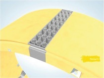
The tolerances of the longitudinal joint conicity, the segment width and the evenness of the contact surfaces are of importance for the design of the segments (Fig. 3). In these areas, which affect both the longitudinal as well as the annular joint, the prevailing forces are introduced into the segments. Providing the predetermined tolerances are adhered to, no decisive additional stresses in the segments are to be anticipated.
Observance of the angle of the longitudinal joint conicity deserves particular attention. The ring normal forces in the longitudinal joints, which are introduced to the supporting system as a result of earth and water pressure load, are transferred further via compressive stresses through direct contact with concrete. The load transfer area is reduced by the longitudinal joints taking on the form of a spring link. The resulting concrete compressive stresses are calculated through this applied load introduction and the necessary tensile strength reinforcement for the most unfavourable combination of twisting angle and ring normal force determined.
Should the permissible longitudinal joint conicity be exceeded the uniform load distribution over the segment width is no longer assured. In addition to the calculated scheduled joint loads these stresses are superimposed in the longitudinal joint by constraining forces caused by excessive articulation. If the demanded tolerance is not observed during segment production, special static proof based on the dimensions actually produced, are required and the reinforcement in the longitudinal joints adjusted to the prevailing circumstances. Experience shows that the tensile strength reinforcement in the longitudinal joints must be increased by roughly 10 to 15 % given an increase of the permissible longitudinal joint conicity from 0.01° to 0.05°.
Care must be taken to adhere to the width of the segment. Through the formation of the segment lining with offset longitudinal joints the abutment for the ring subsequently installed is always formed by 2 segments. According to plan this is geared to a uniform positioning of the segments. The segments are subjected to pronounced load in the longitudinal direction of the tunnel through the driving jack forces. Generally speaking intermediate layers in the form of composite, plywood or triplex panels are installed on the side of the segments facing the jacks, which serve as a defined abutment for the segments and specifically direct the jacking forces through the segments. Given this arrangement, extreme stress in the segments is largely avoided. Apart from defining the abutment the installed intermediate panels also help to compensate tolerances possibly prevailing in the annular joints thus securing a uniform force flow rate.
If the tolerances in the segment width are exceeded to a large degree, the intermediate panels are unable to compensate the differences, and the affected segments are subjected to load as a “shear wall”. Given the prevailing jacking forces it is difficult to design the reinforcement to cope with this load case so that cracks in the segments can result.
Extremely high demands are posed on the position and design of the sealing groove apart from the direct contact points for the segments.
As a single-shell tunnel lining with only a single sealing system is concerned, the groove dimensions must be designed to conform exactly with the selected sealing gasket so that no leakages resulting from ingressing water can occur.
The position of the sealing groove axis is also of great importance as the sealing gasket has been tested and designed with the greatest accuracy for possible joint misalignments and joint openings.
It is only possible to assure that the sealing system functions properly providing that the sealing groove is designed with extreme accuracy.
4 Tendering Demands for executed Reference Projects and resultant Findings
As previously indicated the DS 853 was first taken as the basis for the permissible segment tolerances for the Berlin Mainline Tunnel project.
In the urban rail tunnels previously produced in Germany, tenders did not include such detailed tolerance specifications. The production of segments and the applied tolerances were by and large determined by the contractor. The following excerpts from older tenders substantiate this:
Under point 5.4.1 – G “Segments” in the list of services all that is said is:
“To assess the offers the JV requires detailed explanations and binding commitments on the following points from the tenderer.
Segments:
• Production, accuracy, testing, trial assembly
• …
• Sealing, test certificates”
Tender requirement on the segment tolerances: Point 9.7.1
“On account of the production accuracy required for a watertight lining – the customary neoprene seals only permit +/- 0.5 mm tolerance – the application of heavy steel moulds with […] a production accuracy of +/- 0.2mm is called for. The contractor is required to provide proof”.
“Apart from the customary checks according to DIN the dimensions of the individual segments have to be examined, each segment at the beginning of production, at least every 25th segment per mould once the required production accuracy is attained”.
The tender for the Berlin Mainline Tunnel, which was produced on the basis for the planned tender for the Finne Tunnel, was based for the first time in Germany, as previously mentioned, on specifications as laid down in the DS 853.0019.
In contrast to the DS 853 dating from 1993 the tolerances for the segment arch length, the sealing groove axis, the evenness of the longitudinal and annular joints, the inner circumferences as well as the maximal permissible assembly misalignment were reduced for the Berlin Mainline Tunnel (see Table 1).
Practically all requirements could met within the scope of execution. Adjustments were necessary for the sealing groove and the inner circumference of the closed ring.
It should be pointed out here that smooth joints for the longitudinal joints and a tongue and groove system in keeping with the state of the art at the time were applied in terms of segment design.
The specifications contained in the tender for the Berlin Mainline Tunnel, which had proved itself in practice, were applied for the Betuwe Route projects. Furthermore a tongue and groove system for the annular joint was taken for the reference draft in similar fashion to the Berlin Mainline Tunnel concept.
The sole change related to specifying the maximal permissible assembly misalignment. This specification was excluded from the tender to allow the contractor a free hand in coming up with the coupling design for the annular joint.
The contractor put forward a number of proposed alterations in keeping with the Finne Tunnel for the North-South urban light railway in Cologne.
The IMM was commissioned to assess these proposals within the scope of the technical appraisal for the Cologne project.
Based on comparative observations relating to the changed tolerance values the IMM concluded that the risk of negative influences could be classified as controllable.
Regarding possible contractual agreements and delimitation of responsibilities the IMM put forward the following compromise solution for the Cologne project, which was accepted by the contractor.
• The prime target for production of the segments remains the objective of adhering to the originally determined tolerance specifications.
• “Exceptions”, i.e. deviations from the tolerance specifications are tolerated for the longitudinal joint conicity to a max. of + 0.017° and a max. of + 0.05 mm for the longitudinal joint evenness if related to a percentaged magnitude of < 1 % for the deviation.
• In contractual terms the fluctuation is merely tolerated by the client. However the contractor still remains responsible. In other words, possible consequences for serviceability relating to damage rectification/redevelopment etc. caused by e.g. spalling, cracks, leakages etc. are to be borne by the contractor.
5 Findings obtained from Reference Projects
Generally speaking feedback on practical experience and the adherence to tolerance specifications and any adjustments possible undertaken are hard to obtain.
Based on the experience gained by the IMM from the Betuwe Route tunnels within the scope of supervision of construction (NB: Ril tolerance specifications were also applied in the tender here) the following findings were obtained.
During the measuring of the segments a number of points emerged as critical, which could not fulfil the requirements of the tender:
• Longitudinal joint conicity,
• Segment width,
• Segment arch length and
• Sealing groove
During segment product the tolerances for these aspects were adjusted to the technical values possible in consultation with the client.
Longitudinal joint conicity: change from + 0.01° to + 0.025°.
The longitudinal joint evenness was retained unaltered at + 0.2 mm.
In this connection, first and foremost increasing the permissible longitudinal joint conicity exerts an effect on the supporting behaviour of the segments as well as on the necessary reinforcement for the longitudinal joints.
The feasibility of the changed tolerance parameters could be confirmed through exact ring execution. The tunnels were produced with a qualitatively high-grade segmental lining.
6 Comparison of
Segment Tolerances
Regulation structure/Reference projects
Table 1 contains the segments tolerances for the following projects and regulations to enable better comparison:
1. DS 853.0019, as of 1993
2. DS 853.0019, as of 1998
3. Ril 853, as from June 1, 2002
4. Ril 853, as from March 1, 2011
5. ZTV-ING, draft 2005
6. ZTV-ING, as of 12/2007
7. Berlin Mainline Tunnel, tender 1995
8. Berlin Mainline Tunnel, execution
9. Sophia Tunnel, tender 1997
10. Sophia Tunnel, execution
11. Botlek Tunnel, tender 1997
12. Botlek Tunnel, execution
13. Rotterdam Statenwegtracé, tender 2003 (identical with the Betuwe Route tunnels)
The requirements for the tender for the Pannerdensch Canal Tunnel and the Groene Hart are identical with those for the Botlek and Sophia; thus repetition is unnecessary.
7 Conclusion
The tolerance specifications for segment production first formulated in Germany in 1993 with the publication of the German Rail Guideline DS 853 (now Ril 853) have largely proved themselves in practice. Slight adjustments to individual parameters have been undertaken. It has been displayed that the by and large strictly formulated high demands on accuracy represent a major assurance for the high quality attained by the end product a “segmental structure produced with a single shell”. In future, it is essential to adapt and comply the sustainability and applicability of these demands to the trend to increase diameters.