Lake Mead Intake Tunnel No. 3
In Las Vegas, Nevada, 90 % of the city’s water supply is obtained from the Colorado River at Lake Mead, behind the Hoover Dam. The Construction of the Lake Mead Intake Tunnel No. 3 will asure the water supply for the future.
Project Background
The Colorado River originates in the Rocky Mountains, fed primarily by the winter snowpack, and flows through the desert southwest of the United States. Along the way, it passes through the Grand Canyon and a series of dams and reservoirs, supplying hydroelectric power and fresh water for millions of people and a variety of uses, including drinking, agriculture, and industry. In Las Vegas, Nevada, 90 % of the city’s water supply is obtained from the Colorado River at Lake Mead, behind the Hoover Dam.
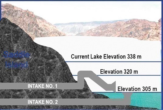
Over the last 9 years, drought conditions that have prevailed in the western USA have contributed to declining reservoir levels all along the Colorado. At Lake Mead, this drought has resulted in a decline in the surface level of about 35 m to elevation 338 m above mean sea level.
The Las Vegas valley currently draws its water from 2 underwater intake structures east of Saddle Island near the western shore (Fig. 1).
If the lake level continues to decline another 18 m, Intake No. 1 will become unusable. If the lake level declines to Elevation 305 m, the second intake will be unusable. The ability to generate electric power at Hoover Dam would also be compromised at this level.
The “Southern Nevada Water Authority (SNWA)” has analyzed this potential problem in conjunction with its analysis of a source of higher quality water. The solution is the construction of a third intake, Intake No. 3 (Fig. 2).
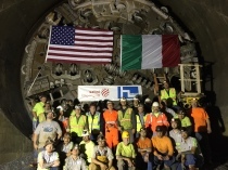
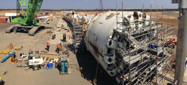
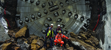
This proposed configuration is complicated by the sedimentary and volcanic geology, the depth of the tunnel with corresponding hydrostatic pressures, and the depth and size of the underwater intake structure at the end of the tunnel. Because of the complexity of the solution, SNWA decided to approach the Project using the design-build delivery method. After a lengthy procurement process, SNWA selected a joint venture of Impregilo S.p.A. (Milano/Italy) and S.A. Healy Co. (Chicago, Illinois/USA) to design and construct the intake tunnel and structure. The joint venture, known as Vegas Tunnel Constructors, appointed Arup USA as the lead designer of the Project, with Brierley Associates as the geotechnical consultant. For the complex tunnel construction, the joint venture selected Herrenknecht AG, Schwanau/D to design and manufacture the Tunnel Boring Machine.
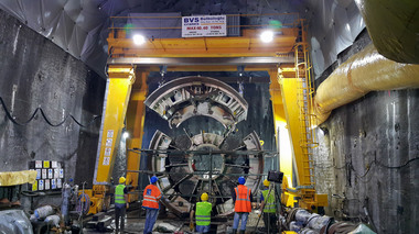
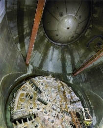
The new intake tunnel will be accessed through an access shaft excavated to a depth of 170 m, with a concrete lining of 9.1 m. The access shaft is being excavated by drill and blast methods with concurrent concrete lining. Extensive probing and pre-excavation grouting is required to advance the access shaft.
At the base of the access shaft, the joint venture will construct a TBM erection chamber and starter tunnel with total length of 137 m. Erecting the TBM in the deep shaft will present another major challenge. A gantry and strand jack system is anticipated.
The Intake Tunnel is 4.8 km in length and will be supported and lined with a gasketed precast concrete segment lining with inner diameter of 6 m, designed for full 17 bar pressure. The precast lining will be a universal type ring and is composed of 5 pieces plus a key with ring length of 1.8 m and thickness of 356 mm.
The Intake Tunnel is primarily located in the Tertiary sedimentary rock of the Muddy Creek Formation. The Muddy Creek is divided into zones of gypsiferous mudstone, interbedded siltstone, sandstone and pebble conglomerate, tan conglomerate, and reddish brown conglomeratic breccias. At the Intake end of the tunnel, excavation will be through an older Tertiary conglomerate of the Red Sandstone Unit and basalt of the Callville Mesa Unit. Throughout the alignment, dozens of faults, some with major vertical displacement, will be encountered. Although many of these faults have been filled with secondary mineralization, it is presumed that the formations are directly recharged by the waters of Lake Mead and that large amounts of water will be encountered.
The Intake Structure at the end of the tunnel is designed as a structure that will be constructed near the shore of the lake, then towed and lowered into an underwater excavation. The structure is designed with a double bulkhead and a reception dock for the TBM.
Dual Mode TBM
The TBM for Lake Mead Intake No. 3 is a single shield machine for difficult hard rock ground conditions with some potential for high groundwater inflows and high hydrostatic pressures. The geotechnical baseline report (GBR) identifies at least 2 intervals that would require “pressurized face excavation, extensive pre-excavation grouting and ground treatment, or a combination thereof”. The TBM specification asks for a “fully shielded TBM articulated as required with the ability to operate in a pressurized and unpressurized mode and tunnel through rock, soil and mixed face conditions”. The machine should be prepared for probing and ground improvement ahead of the TBM (12 periphery positions, 4 face positions), rapid closure within 120 seconds if operating in an unpressurized mode and layout for operation and access up to 17 bar (247 psi).
The layout of the TBM is based on the experiences from to some extent comparable TBMs as presently under operation on the Hallandsas Project (high pressure dual mode shielded rock TBM) in Sweden and the Arrowhead Project in San Bernardino, California (open mode shielded rock TBM with extensive pre-excavation grouting equipment) as well as on numerous applications of “high pressure” Mixshields.
In order to cope with the heterogeneous ground conditions, the Lake Mead TBM can therefore be operated in open mode (mucking out by a centre screw conveyor and tunnel belt conveyor) as the major mode of operation and in semi closed or full pressurized closed mode (muck transportation by a full size slurry circuit) to overcome limited zones of extremely difficult ground conditions.
The following operation modes/mining scenarios are considered for the machine layout:
– Continuous open mode excavation with centre screw conveyor and belt conveyor for muck transport
– Cyclic open mode operation with consecutive pre-excavation grouting and mining cycles (Fig. 3)
– Cyclic closed mode operation under reduced face pressure with consecutive pre-excavation grouting and mining cycles and open mode face access for cutter check and maintenance
– Closed mode operation under full face pressure with pre-excavation grouting for open mode face access
– Closed mode operation under full face pressure with hyperbaric face access in air or even mixed gas/saturation mode.
Open mode operation
In open mode operation, the material is transported by buckets and muck channels into the centre arranged muck hopper in the cutterhead from where it is extracted by a horizontally arranged screw conveyor past the ring erection area. From the screw conveyor discharge point a belt conveyor transports the excavated muck along the complete back-up section to the tunnel continuous belt conveyor.
The muck chute layout in the cutterhead allows a first stage dewatering of the muck inside the excavation chamber. The use of a primary screw conveyor for open mode operation ensures the best possible and most reliable option for rapid closure of the excavation chamber in case of sudden water ingress by closing the rear discharge gate. Although a heavy screw auger may not be the most “elegant” solution for open mode muck transportation, the key advantage of rapid closure is essential. In addition, the closed screw system provides good protection of the ring erection area against water spillage in wet conditions.
The ability to handle water laden muck in open mode operation is considered to be one of the key elements. A large settlement basin is located under the screw conveyor discharge area to collect water spillage. The basin is connected to a flushing circuit containing as well a small treatment plant installed in the rear gantry area. This onboard circuit – treatment plant configuration minimizes the risk of fines settlement in the spillage collecting basins due to a permanent flow of flushing water and reduces the solids content in the discharge water (overflow quantity) to be pumped out of the tunnel.
Probing and pre-excavation grouting
The machine is equipped with 3 permanent installed drill rigs (Fig. 4). 2 of them are located inside the shield for the face positions, the third one is located behind the ring erection area for the periphery positions. An additional fourth drill rig could be temporarily installed on the erector. Probing and drilling ahead can be done in open mode and, for the majority of the positions, also in closed mode conditions using blow out preventer units. 2 identical pre-excavation grout plants are installed on the trailing gear.
Closed mode operation
In closed mode operation, the machine will operate in full slurry mode following the MixShield principle with an air bubble for face pressure control (Fig. 5). This system allows the machine to operate in closed conditions but with free adjustable face pressure depending on the in-situ requirements. Closed mode operation but with reduced pressure (lower than full water head) is possible depending on the given face or ground conditions. The possibility for a water volume balance of the entire slurry circuit also allows a clear picture of water inflow quantity through the face during reduced pressure operation.
The change of mode of operation does not require modification at the cutterhead. As soon as the rear discharge gate of the screw conveyor is closed the excavation chamber is isolated and the system is closed. Before restarting in closed mode the screw casing is hydraulically retracted to clear the cutterhead center area and the tunnel slurry circuit and above ground treatment plant is brought into operation.
The entire equipment and installation for the closed mode slurry operation is permanently on board. The TBM is equipped with a submerged wall gate and a rock crusher in front of the suction grill and all pipework, pumps, compressed air and circuit installation in the TBM and along the trailing gear. The system is completed with slurry circuit installations along the tunnel and shaft and the entire above ground treatment and slurry plant.
The tunneling system is prepared for hyperbaric face access. A standby decompression chamber equipped with oxygen decompression system is permanently located behind the ring erection area. This chamber can be connected by an access tube to the rear shield bulkhead providing access to the drill chamber behind the front shield bulkhead. The size of the decompression chamber is large enough to allow for extended decompression times and to perform the complete decompression process. In addition, the system is prepared for the use of mixed gas breathing systems for higher chamber pressures. The breathing gas mixtures can be Trimix or Heliox. For extended chamber time under high pressure, the tunneling system is prepared for a shuttle transfer of the crew between the airlock and a hyperbaric habitat at the bottom of the access shaft.