Removal of a local Scale Deposit in a Tunnel Drainage System
 Quelle/credit: IAG BOKU Wien
 Quelle/credit: IAG BOKU Wien
 Quelle/credit: IAG BOKU Wien
 Quelle/credit: IAG BOKU Wien
 Quelle/credit: IAG BOKU Wien
 Quelle/credit: IAG BOKU Wien
 Quelle/credit: IAG BOKU Wien
In the Vienna Lainzer Tunnel scale deposits were a substantial problem in a section of the underground water drainage system. The application of hydro-mechanical cleaning methods was no longer feasible and it would have been complicated to rebuild the drainage system. This section was thus treated with a 10 % hydrochloric acid solution between November 2012 and April 2014. In this way, it was possible to remove the scale deposits to such an extent that the drainage system could be purged by conventional means. These tests were accompanied by extensive monitoring, camera inspections and water analyses. It was proved that the application of hydrochloric acid had no harmful effects on the runoff ditch.
1 General conditions
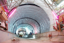
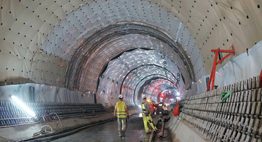
Parts of the Lainzer Rail Tunnel in central Vienna including the emergency exits (EE) were designed relieved of pressurized water. This is made by tunnel drainage pipes at both sides of the tunnel tube. Plastic membranes lines are used for sealing the vault set between the inner and outer shells.
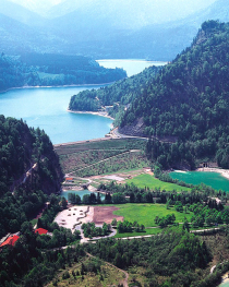
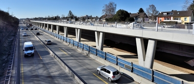
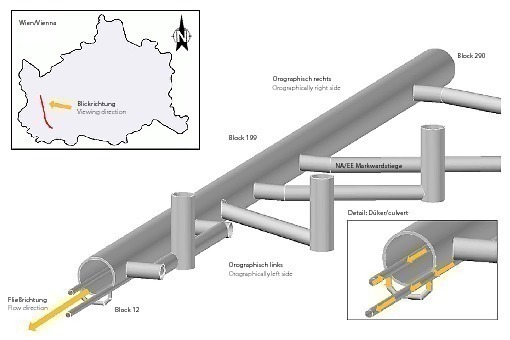
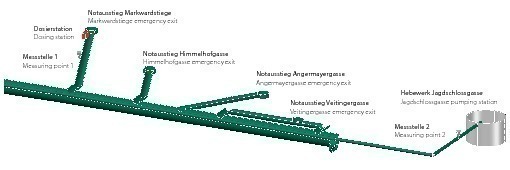
In one of the emergency exits, the EE Markwardstiege (Figs. 1 + 2),
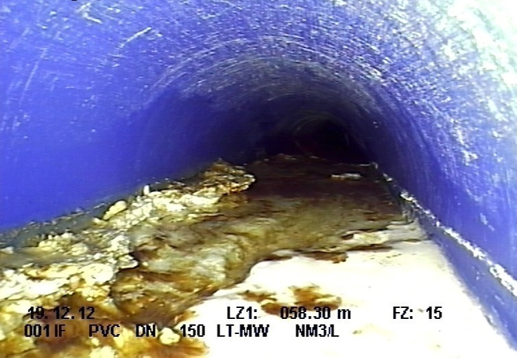
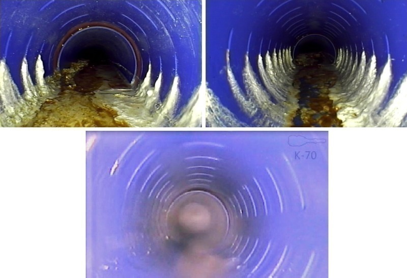
scale deposits caused considerable problems in one section of the tunnel drainage. The drainage system was filled to roughly two-thirds of its height with extremely hard calcite deposited over a length of some 4 m (Fig. 3). As a result, neither the usual hydro-mechanical cleaning methods (vibration nozzle, chain scraper and rotating nozzle) for loosening the scale deposits were feasible nor integrated camera inspections to determine the state of the drainage system were possible. To ensure sustainable structural safety and serviceability it is essential that all underground drainage systems are properly accessible and in a serviceable state.
In order to make sure that cleaning could be carried out again properly in the section affected by scale deposits, a number of possible solutions were considered. As a structural solution, it was considered removing the inner shell in the affected section and replacing the entire drain pipe there. However, the decisive disadvantage in this case was the high structural outlay, the destruction of the waterproofing level as well as associated tunnel closures.
A further possibility that was discussed was treating the scale deposits with hardness stabilizers. During the building of the primary drainage system for the Lainzer Tunnel polysuccinimide bricks were applied. Nevertheless, no obvious effect on the scale deposits in the tunnel drainage systems could be observed. Due to negative experiences previously encountered in other sections of the Lainzer Tunnel involving the pronounced growth of bacteria, no attempt was made to use a hardness stabilizer in liquid form consisting of polyaspartic acid or other organic acids in liquid form.
It was hypothesized that the most effective method would be to purge the affected drain section with a 10 % solution of hydrochloric acid instead of the above-mentioned organic acids. For that purpose, the following aspects were discussed in advance:
Reaction products of hydrochloric acid and scale deposits: with various analytical methods (x-ray diffraction and simultaneous thermoanalysis) it was proved that the scale deposits consisted of calcite (CaCO3). When hydrochloric acid reacts with the scale deposits, the calcite is dissolved. This results in the production of the salt calcium chloride (CaCl2) with the emission of CO2 and the formation of H2O. Calcium chloride is extremely water-soluble and splits up into the ions Ca2+ and 2Cl–, in keeping with the following equation:
Thus the addition of hydrochloric acid to the drainage water signifies the addition of chloride ions.
Effects on the drainage water: the drainage water containing hydrochloric acid flows from the EE Markwardstiege over a distance of some 3.5 km through the tunnel drainage systems before it is discharged into the runoff ditch at the Jagdschlossgasse pumping station. On the way between the admission point and the runoff ditch the acid is diluted when it encounters more underground water entering the drainage system, which results in a reduction of the chloride ion concentration. Furthermore additional calcium carbonate and consequently its carbonates and hydrogen carbonates are transported to the system, resulting in sufficient buffering in the drainage water. An approximate simulation of the water content in the entire drainage system indicated that no legal limit values of chloride ions or the pH-value would be exceeded by the proposed added amounts of hydrochloric acid.
Effects on the tunnel: the entire underground drainage system consists of PVC pipes, which are according to the manufacturer’s specifications resistant to a 37 % solution of hydrochloric acid. During construction the drainage pipes were installed as full casings and later cut open at the cleaning shafts. As a result there is no contact between the drainage water and the shaft bottom made of concrete. Indeed there is no contact between the hydrochloric acid and cementitious materials at any point in the drainage system.
Industrial safety: the tests were only handled by trained staff so that no danger from the aspect of occupational safety arose. For other members of staff, who were involved in working in the tunnel, corresponding warning signs were provided.
Case of emergency: if passengers or rail staff would have needed to use the EE Markwardstiege in the case of an emergency this would not have resulted in any dangerous situation occurring at the dosing station as its position was fixed outside of the evacuation route. Furthermore the legally determined storage space in accordance with Guideline A12 of the Austrian Fire Service Association for stairways and passenger lifts was adhered to.
After positive assesment of the above-mentioned aspects the HCI test was commenced on Nov. 24, 2012. The addition of 10 % hydrochloric acid to the drainage water (initially 280 ml/h; a further 280 ml/h was added since Oct. 28, 2013) was carried out via a cleaning shaft of the tunnel drainage system. Two dosing pumps from a 140 l and a 500 l tank, each with its own collecting vessel, were used. During the entire duration of the test the conductivity, pH-value and temperature of the drainage water were measured and registered every 10 minutes – 50m beyond the point of admission (Measuring Point 1) and 3.5 km away, prior to the drainage water being discharged into the runoff ditch at the Jagdschlossgasse pumping station (Measuring Point 2). From that pumping station the entire drainage water is pumped from a collecting basin into the channel system, representing the runoff ditch.
2 Measurement results
2.1 Underground Water Quantity
During the test evident changes in the amount of underground water were observed. Between January 2013 and the end of July 2013 a substantially higher amount of underground water was recorded in the affected drainage at the EE Markwardstiege (approx. 150–200 ml/s) than during the remaining part of the test (ca. 20–50 ml/s). The amount of underground water at the Jagdschlossgasse pumping station from both tunnel drainage systems rose to a total of roughly 1.5 l/s. A higher amount was recognizable here as well during the period between January 2013 and the end of July 2013 (approx. 3 l/s).
2.2 Water analyses
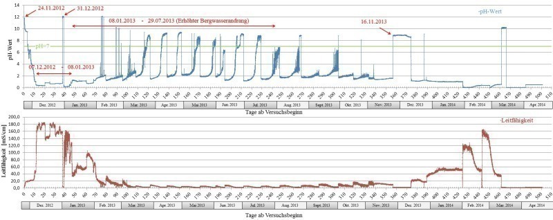
Figs. 4–6 display the electric conductivity and the pH-value for the two measuring points as well as the chloride ion concentration of the water shortly before the Jagdschlossgasse pumping station in the form of time series.
Markwardstiege Emergency Exit (Measuring Point 1)
Starting with a pH-value of 11.7 and a conductivity of 2.2 mS/cm on Nov. 24, 2012, the parameters changed swiftly within two hours after the 10 % solution of hydrochloric acid had been added. During the progression of the trial the pH-value dropped, the conductivity rose. From Dec. 7, 2012 a level was reached (low pH-value of around 0.4 and high conductivities of up to 180 mS/cm), which lasted with slight fluctuations until Jan. 8, 2013. Around Dec. 31, 2012 a brief increase in the pH-value is recognizable. From Jan. 8, 2013 dynamic behavior of the pH-value and the conductivity developed at the same time as an increase in the incidence of underground water. After March 12, 2013 this transformed to practically identical periodic characteristics for the pH-value and the conductivity, which showed the following pattern:
an increase of the pH-value up to 9.3 (based on a starting value of pH = 1.5–2.0)
a drop in the conductivity down to 1.8 mS/cm
after attaining the maximal pH-value and the minimal conductivity an abrupt change to the starting level prior to the given period occurred
These regular fluctuation periods lasted until July 29, 2013, with the duration of the periods once again extending successively as from this point-in-time. At the same time of this extension in the duration of the periods, a reduction in the incidence of underground water was registered. From Nov. 16, 2013, no hydrochloric acid was added for several days.
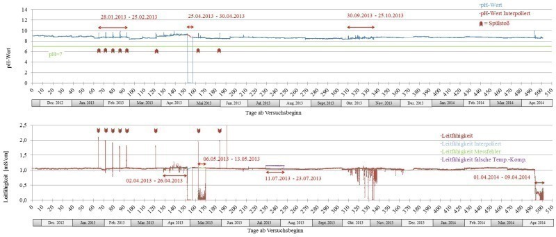
Jagdschlossgasse Emergency Exit (Measuring Point 2)
The course of the drainage water parameters displays a clearly more homogeneous picture than those from the Markwardstiege. The pH-value varied between 8.8 ± 0.3 and the conductivity around 1.1 mS/cm (Fig. 5).
From Jan. 28, 2013, five successive peaks revealed that the pH value had increased to 9.8 and the conductivity to values of around 2.2 mS/cm. These peaks occurred at intervals of seven days. During the following months, three further peaks of this behavior were detected. In addition two drops in the data curves were recorded between April 25 and 30, 2013 (pH-value and conductivity) as well as between May 6 and 13, 2013 and April 1 and 9, 2014 (only in the case of the conductivity).
Between July 11 and 23, 2013 varying high values for the conductivity were measured. During the period from April 2 to 26, 2013 and from Sept. 30 to Oct. 25, 2013 the datasets displayed slight “signal noise”.
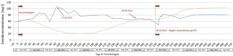
Chloride ion concentration
The chloride ion concentration of the water samples at Measuring Point 2 at the Jagdschlossgasse pumping station displayed clear fluctuations. At the start of the test the concentration rose from 58 mg/l to a maximum of 106 mg/l on Feb. 27, 2013, directly afterwards the concentration fell again. On Sept. 5, 2013 67 mg/l were measured.
The amount of added 10 % hydrochloric acid solution in relation to the chloride ion concentration was not changed during the first year of the test. Nevertheless, the chloride ion concentration rose up to 106 mg/l between Jan. 2013 and the end of July 2013. But at the same time the incidence of underground water was increasing too. Although the amount of 10 % hydrochloric acid was doubled from Oct. 28, 2013 no change in the chloride ion concentration was recorded. During the progression of the HCl test the chloride ion concentration remained constant at around 80 mg/l and changed only minimally until the test ended. From early August 2013 until the end of the test in April 2014 the incidence of underground water no longer displayed any noticeable fluctuations.
This signifies that the concentration of chloride ion is influenced only locally by the test and there is no influence on the chloride ion concentration of the whole drainage water before discharging it into the runoff ditch.
2.3 Visual checks
It is easy to see that the scale deposits at the base of the drainage system diminished during the course of the HCl test (Fig. 7) and could be removed after cleaning. In this way, conventional methods could be used again for cleaning purposes.
3 Data interpretation
3.1 Markwardstiege emergency exit (measuring point 1)
The carbonates above Measuring Point 1 slowly began to dissolve with the start of the test on Nov. 24, 2012. The hydrochloric acid flowed successively over the existing scale deposits thus being neutralized. This process lasted until Dec. 7, 2012. Subsequently there was no longer contact with the carbonates in front of Measuring Point 1 so that the hydrochloric acid could flow through to Measuring Point 1. This can be traced from the pH-value and the conductivity (Fig. 4).
On December 31, 2012, the continuous addition of hydrochloric acid was interrupted in order to find out how rapidly the system would react to the changed water chemistry. The data indicate an extremely quick increase in the pH-value and a decrease in conductivity beginning a few minutes after dosing ceased. Tthe starting values were attained after some 30 minutes.
Beginning on 8 January 2013 a strong increase in the amount of drainage water was recorded. This resulted in the hydrochloric acid being diluted, the pH-value of the drainage water increased and the conductivity diminished. The increase in the amount of drainage water at the beginning of Jan. 2013 started with roughly 1.5 months delay in comparison to the increased precipitation. One possible explanation for the periodic fluctuations of the conductivity and pH-value in the period from Jan. 8 and July 29, 2013 would be an underground “vug system”. This system would be possibly filled with underground water, which empties itself from time to time given an increased incidence of drainage water. Consequently, these fluctuations would represent progressing dilution and a sudden rise in concentration following each ebbing of this ”vug system” (Fig. 4).
As from the end of July 2013, the incidence of underground water once again dropped. As a result, the amount of time needed for this possible “vug system” to fill itself grew, which is recognizable from the extended durations of the periods for the pH-value and conductivity fluctuations.
3.2 Jagdschlossgasse emergency exit (measuring point 2)
The erratic increase of the pH-value starting on Jan. 28, 2013 (arrows in Fig. 5; periodically at eight points) show a good correlation chronologically to planned cleaning phases. It indicates drainage cleaning works where older, alkaline deposits (cement residue, concrete particles or scale deposits with a high amount of portlandite) were removed from the main tunnel’s drainage systems thus causing the pH-values to rise.
The pronounced drop in the pH-value and the conductivity between April 25 and 30, 2013 can be attributed to the measuring cells being distorted. When their position was corrected both measuring cells at once again provided correct data corresponding to the previous results. The same applies for the periods from May 6 to 13, 2013 and from April 1 to 9, 2014 for the data on conductivity. The inhomogeneity of the datasets from April 2 to 26, 2013 and from 30 Sept. to Oct. 25, 2013 can also be correlated with cleaning operations in the drainage systems.
During the period from July 11 to 23, 2013 excessively high values were measured for the conductivity as the wrong temperature compensation factor was applied following calibration. After this factor was rectified data corresponding to the previous results were measured.
4 Discussion
The use of hydrochloric acid to remove calcium carbonate is quite common practice. As it was proved that the concerned scale deposits consisted of calcite it is clear that these could be dissipated by a 10 % hydrochloric acid solution.
References are also several times made to the fact that apart from calcite, brucite (magnesium hydroxide – Mg(OH)2) [5][6][7] and Portlandite (calcium hydroxide – Ca(OH)2) can form scale deposits in tunnel drainage systems [8][9][10].
These compounds were not identified in the scale deposits at the Markwardstiege. Diluted hydrochloric acid would also have been suitable for dissolving such scale deposits [11], which would substantially enlarge the future ranges of application.
With the help of constant monitoring and water analyses it could be proved that no legally determined limit values were exceeded before being discharged into the runoff ditch. In addition, it could also be proved that there seems to be no unfavorable influencing of the drainage water’s chloride ion concentration when transferring it to the runoff ditch (Fig. 6). Additional no increase in the chloride ion concentration took place during the first year of the test in spite of the amount of hydrochloric acid added staying the same during an increasing amount of underground water. After the amount of hydrochloric acid added was doubled during the second year of the test no increase in the chloride ion concentration was measured. Thus the input of chloride ions from an outside source seems probable, resulting possibly from the delayed input of the thawing salt used on the surface in winter. If the chloride ion concentration would have been influenced by the test only, the concentration would decrease when the incidence of water increased.
Due to the successive removal of the scale deposits the drainage system was cleared and subsequently easy to clean and service (Fig. 7), therefore the goal of the HCl test was attained. However, it is necessary to point out that the application of 10 % hydrochloric acid solution cannot replace periodic cleaning of the drainage systems as the casing slots of the partial drain pipes can still clog.
Furthermore the application of an acid – regardless whether the acid is organic or hydrochloric acid – is impossible if it comes into contact with cementious building materials. However, 10 % hydrochloric acid seems to make sense for local, time-restricted applications in order to reduce heavy scale deposits in drainage systems. It is nevertheless important to point out that this is only possible with the use of intensive monitoring.