Long-term Behaviour of Plastic Sheet Membranes
 Quelle/credit: FH Münster
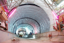
![Standard cross-section of the underground urban railway facility Dortmund Hauptbahnhof with trenchless platform enlargement [1]](https://www.tunnel-online.info/imgs/1/2/7/8/9/4/8/bild2-kdb-dortmund-05f1cc382fb663a0.jpeg) Quelle/credit: Ingenieurbüro Maidl & Maidl
Quelle/credit: Ingenieurbüro Maidl & Maidl
![Connecting the existing membrane to the new structure [2]](https://www.tunnel-online.info/imgs/1/2/7/8/9/4/8/bild3-kdb-dortmund-d0c37e0fd393dccf.jpeg) Quelle/credit: Ingenieurbüro Wendt
Quelle/credit: Ingenieurbüro Wendt
 Quelle/credit (4): FH Münster
 Quelle/credit: FH Münster

 Quelle/credit (3): FH Münster

Tunnels are technically complex to produce and represent cost-intensive infrastructure projects. Their technical qualities must be maintained in order to ensure that the mobility of traffic is assured on a lasting basis. These structures are designed to last for up to 100 years commensurate with their technical codes of practice. The tunnel‘s waterproofing must also comply with these requirements on service life. After all, it is practically impossible to repair the seal of two-shell tunnel structures. At present the issue of the long-term behaviour of tunnel waterproofing is being examined in a number of
research projects. In this connection, a great deal depends on existing reference values for membranes that have been previously installed.
Within the scope of the redevelopment of the Dortmund Hauptbahnhof underground urban railway facility (Fig. 1) roughly 43 year old plastic sheet membranes (KDB) were uncovered. This report presents the results of a study into the mechanical behaviour of these old plastic sheet membranes.
1 Description of Project
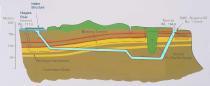
The Hauptbahnhof urban railway station was set up during the 1970s as a two-storey framework building by means of cut-and-cover beneath the tracks of Dortmund‘s Central Station. The soil is composed of heterogeneous fill material down to an area roughly 9 m below ground level, i.e. down to the level of the intermediate ceiling. This is due to the fact that around 1910 an extensive conversion scheme was carried out on the then railway tracks with these tracks raised from street level for relocation on an embankment as is still the case today. Silt with peat enclaves is to be found beneath the fill and the marl level is located roughly in the vicinity of the floor of the urban rail structural system. Effects caused by water result from seepage water; the groundwater is to be found beneath the floor of the structure.
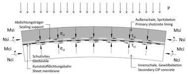
The urban rail network no longer complies with current demands relating to an efficient, safe and attractive system of its kind in terms of transportation and construction. As a result, it is being upgraded and enlarged. The main measures relate to widening the platforms at the sides (Fig. 2). This is being executed by trenchless means in order to ensure that ongoing operation of the DB tracks passing above the urban rail system is not curtailed. The Dortmund Foundation Engineering Office and the Ingenieurbüro Maidl & Maidl, Bochum are responsible for planning these construction measures. The contract for execution (roughwork, Urban Rail Line 1, Lot 20) was awarded to Wayss & Freytag Ingenieurbau AG in March 2014. The reinforced concrete structure for the platform enlargement is being connected monolithically to the existing platform. It takes the form of a watertight concrete structure. The current sealing system for the existing setup comprises PVC plastic sheet membranes and lateral drainage lines. The waterproofing systems were installed around 1973 so that they are now roughly 44 years old.
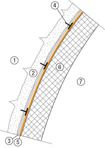
To produce a watertight connecting area the sheet membranes present in the upper area of the existing wall were exposed from the outside and provided with new plastic sheet membranes (Fig. 3). The welded joint strip provides the sealant for the watertight concrete structure for the enlargement structures.
2 Taking Samples
In order to connect the enlargement structure to the existing one the drilled pile wall was demolished by means of the cable-saw method so that the structural concrete wall with the externally located sheet membranes belonging to the existing structure was exposed from the outside (Fig. 4).
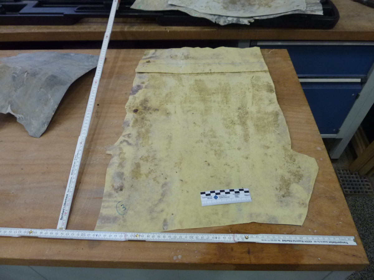
Extensive sample material could be removed for further investigations in these areas. Within the scope of the excavation work, dry and in some cases wet soil conditions were encountered in these areas.
Upon exposure of the sheet membrane, in each case a membrane some 1.4 mm thick became visible. This sheet membrane was covered on each side with a further, roughly 1 mm thick sheet membrane, which were probably intended as protective sheets. A protective layer in the form of non-woven fabrics was not installed. The sealing system appeared to be undamaged in the exposed areas. The connection provided by the welded seams for the sheet membranes in the case of the samples obtained gave no cause for concern following a visual examination. In accordance with the details provided in the pertinent manual dating from that time a 1mm thick PVC flexible film „Trocal TF“ was foreseen as waterproofing for these areas. This seal was embedded in a 1 mm thick PVC rigid film „Trocal TS“ as outer protective layer.
The samples that were removed reveal less flexibility than the comparable plastic sheet membranes available today. It was easily possible, however, to move the film manually.
3 Executing Testing and Results
3.1 Determining the
tensile Properties
All in all, advance tests were undertaken on three different samples, which were removed from different parts of the structure.
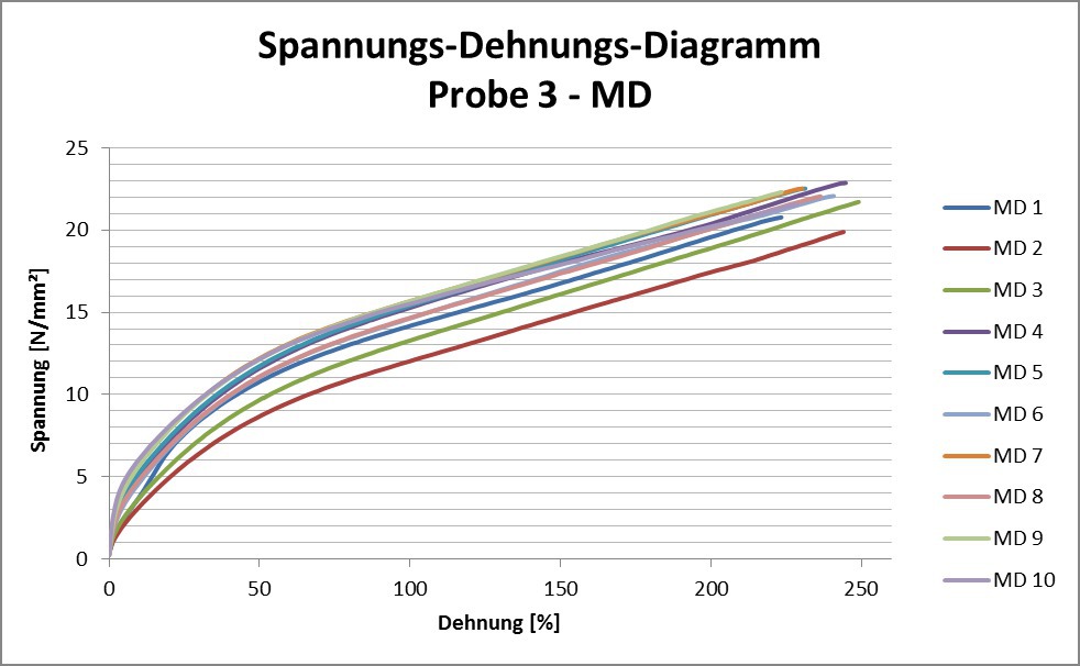
Determining the thickness according to DIN EN 1848-2 resulted in a thickness of 1.49 mm for the flexible film ,with the value for the rigid film equalling 1.03 mm.
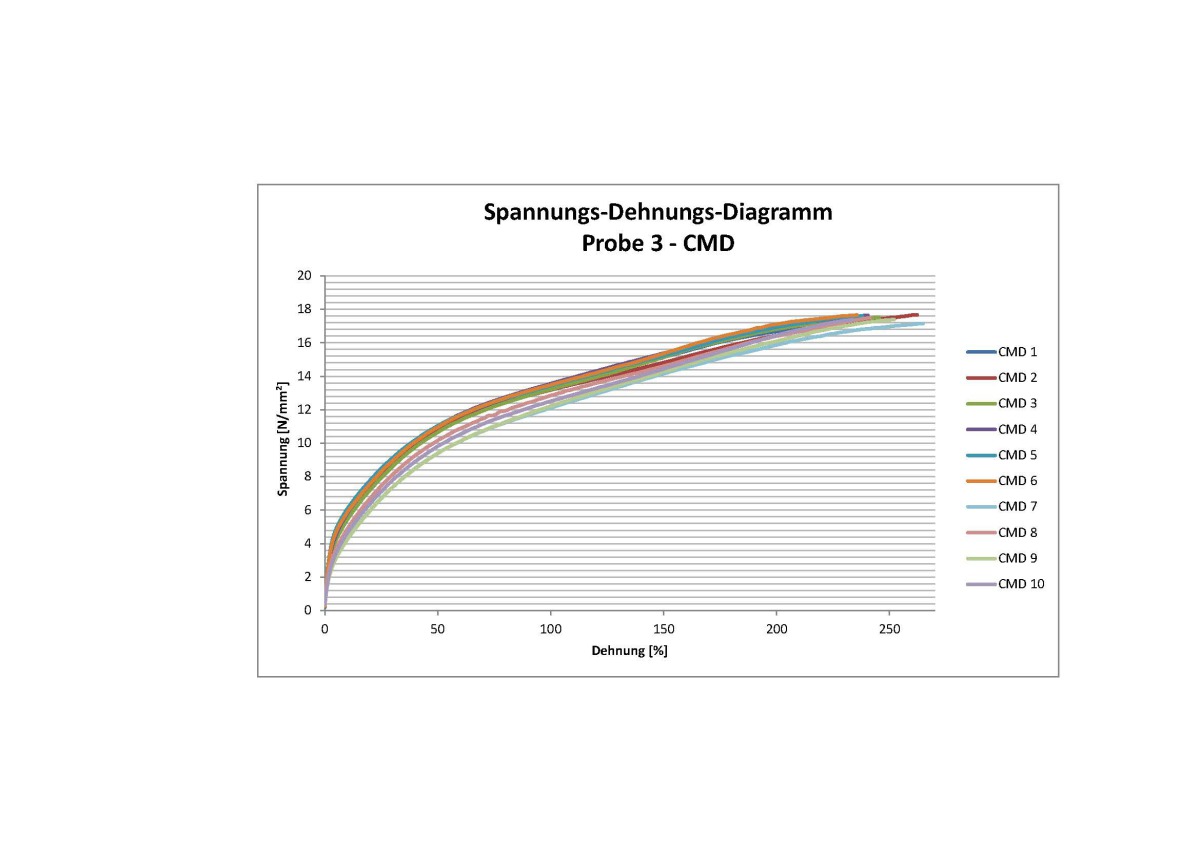
Dumbbell specimens (in each case ten per direction) were produced from samples 1 to 3 and tested for tensile strength according to DIN EN ISO 527. The following investigations that are listed were carried out on the internally located sheet membranes. The production direction could be established for the samples on the basis of the course of the weld seam. The tensile tests were for their part undertaken in MD (machine direction) and CMD (cross machine direction). In Tables 1 to 3 the results of the sets of ten tensile tests are shown per direction. The corresponding force-strain diagrams of some dumbbell specimens for the removed sheet membranes are shown in Figs. 5 + 6.
No defined demands on the mechanical behaviour of he sheet membrane could be found in the available construction files. In the following individual demands from the latest codes of practice are listed. Thus for instance, the ZTV-Tunnel [3] dating from 1985 calls for tear strengths of > 10 N/mm² for the sheet membrane. In the case of the elongation at tear a value of > 200 % is called for in this code of practice. The currently valid technical code of practice (TL/TP-ING [4] requires an ultimate strength of > 12 N/mm² in a longitudinal and crosswise direction for sheet membranes made of PVC-P. The ultimate elongation in a longitudinal and crosswise direction should accordingly amount to > 250 %. these values are also to be found in the recommendations on sealing systems in tunnelling issued by the German Geotechnical Society [5]. All the values for the tensile strength from the codes of practice are adhered to for the examined samples in a longitudinal and crosswise direction.
In the case of failure strain, 31 of 60 dumbbell specimens that were tested were in excess of 200 %; in the case of samples 3 this value was adhered to by all the investigated samples. In the case of 12 samples that were examined, the determined failure strain lay in the interval 190-200 %. In the interval of 180-190 % for failure strain five values were obtained during the examinations and seven values in the 170-180 % range. Altogether failure strains of less than 170 % were established in the case of five samples.
At present no details are available about the existing failure strains and tensile strengths for the sheet membranes when they were installed: this also applies to retained samples at the time of production.
Investigations relating to the actual load imposed on sheet membranes in tunnelling after installation are conducted in [6] and [7]. In this connection among other things the question as to what extent loads on the sealing system can occur in the combination of tunnel inner shell, the sealing system geotextile protective layers and the shotcrete outer shell.
In the process it is revealed that the robustness values thus established are generally considerably lower than the values contained in the codes of practice. It should be emphasised at this point that local peak strains can occur on the sealing system, which are very difficult to quantify with regard to localised strains affecting the sealing system.
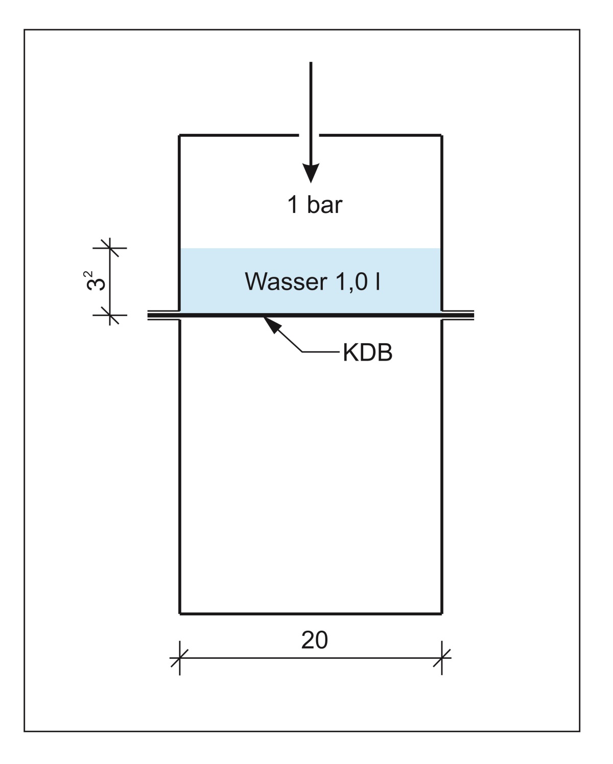
3.2 Investigations on multiaxial Elongation/Watertightness
Apart from establishing the properties of the sheet membranes that have been listed so far, behaviour under multiaxial load was of interest within the scope of the study. Towards this end several samples were installed in a circular steel vessel (20 cm in diameter) one after the other (Fig. 7). A litre of water was added to each of the samples and subsequently the closed system subjected to compressed air (1 bar). Fig. 7 shows the deformation affecting a sample that has been removed on the right. No ingressing water was identified in the lower section of the steel vessel. The samples remained watertight under the described test conditions over a period of several days.
3.3 Investigations by the Manufacturer
Sika carried out its own investigations [8] on membranes that were made available. Towards this end the membranes were examined by means of infrared spectroscopy (IR) as well as x-ray fluorescence analysis (RFA). It emerged that it was highly probable that the sheet membrane located in the middle of the sealing system is identical to the product „Trocal T“, which is a PVC membrane. The two external membranes were identified with high probability as the „Trocal TS“ protective layer using the IR and RFA methods.
Through identifying these membranes corresponding retained samples dating back to 2000 could be traced, which are available at the Sika company and probably possess comparable material properties. For purposes of comparison the tensile properties of these membranes were tested. In the process maximum tensile strengths ranging from 17.96 to 18.79 N/mm² were established. The failure strains amounted to between 327.5 and 359 %. Owing to the different storage conditions of the installed samples and the retained samples as well as the different age states it was difficult to reach a proper assessment so no more than a preliminary one was arrived at.
Within the scope of further investigations after the removed samples were cleaned they were welded together with new sheet membranes of Type Trocal T. In this connection peeling values in keeping with DIN EN 12316-2 of 415 NN/50 mm were determined.
3.4 Investigations on Welding Suitability
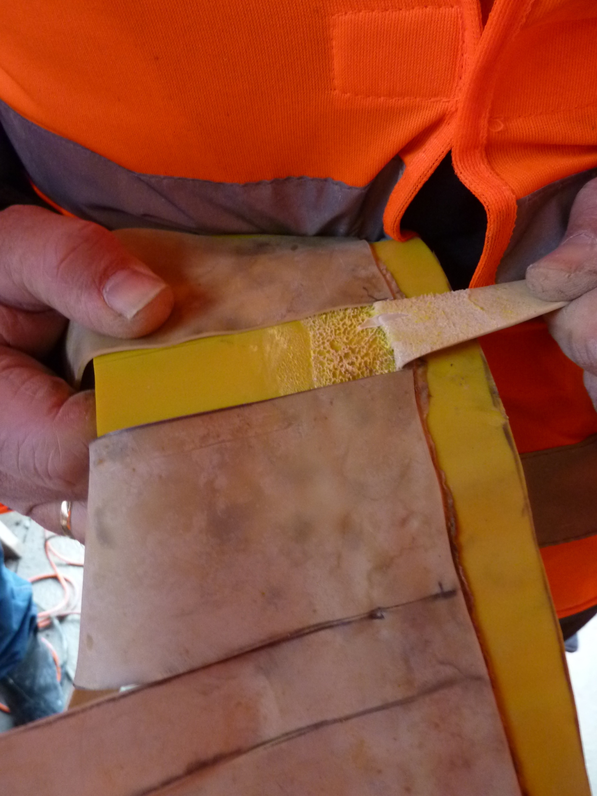
As the exposed sheet membranes are integrated in the new sealing system, the basic practicability and the optimal process conditions for „old“ and „new“ welding connections had to be examined in advance.
In order to clarify this issue the removed samples were first of all cleaned within the scope of various on-site tests. This was accomplished with a special cleaner based on solvents for the seam areas of sheet membranes.
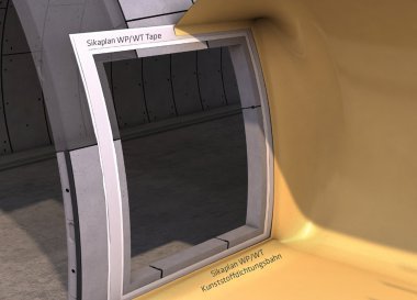
Then the removed PVC plastic sheet membranes were welded together manually with a new PVC sheet membrane (Type Sikaplan WP 1100) by means of a hot-air method (Fig. 8). The new sheet membrane is a PVC-P sealing membrane with a signal layer.
The membranes were connected using differently set hot air temperatures. These ranged from 280 to 380 °C. In this respect the connecting temperature exerted an influence on the peeling behaviour of the membranes there.
These connections were subsequently pulled apart by mechanical means. In the case of higher connecting temperatures various surface changes to the sheet membrane in the form of very rough surface formations were identified in the contact area of the seam joint (Fig. 9). In the case of such a surface formation the peeling force was also low.
This surface structure between the sheet membranes was not so clearly evident given a temperature range for the connection of roughly 300 °C. In this temperature range the highest connecting strengths between the membranes were identified. On account of these findings the weld connections between the exposed sheets and the new sealing system were produced using these temperatures.
4 Summary
During the investigations carried out on the plastic sheet membranes made of PVC, which were roughly 43 years old at the time of their removal, tensile strengths were established, which completely fill the requirements of current codes of practice. In the case of the failure strain values of > 200 % were attained for 51 % of the installed samples; the remainder stayed below this value. The lowest value for the failure strain was in this case established as an individual value of 101 %. Furthermore the behaviour of the sheet membrane under multiaxial load as well as the suitability for welding of the removed samples was examined. The samples withstood a water pressure load of 1 bar for several days on end. With regard to the suitability for welding of the samples the influence of the joint temperature on the connecting strength of the seams was ascertained.
The sealing system was fully intact at the exposed points of the samples and without damage even after being installed for more than four decades; this also applies to the welding seam connections of the sheet membranes.
The author would like to express his gratitude to Messrs. Sika for their support with the site tests as well as the investigations and research they undertook of their own accord.