Single-Shell watertight segmental Linings in Germany
During the period between 1974 and 2008 more than 110 km of tunnel was successfully produced in Germany using single-shell, watertight concrete segments with an internal diameter ranging from 2.37 to 12.35 m. In other words, during 34 years in Germany an average of 3 km of tunnel was produced per annum – with a substantially increasing tendency during recent years – by means of shield excavation with single-shell or monocoque segments made of reinforced concrete. The following report provides an overview.
In Germany up until the end of 2008 more than 2.5 million m² of excavated area – pertaining to the external diameter of tunnels – was permanently secured using a single-shell, watertight segmental lining. Table 1 provides an overview of the tunnels built so far in Germany using single-shell, watertight segmental linings made of reinforced concrete.
The proportion of Under-ground, urban railway and rapid transit system tunnels amounts to 41 % (45 km), railway tunnels 25 % (27 km), supply and disposal tunnels including miscellaneous tunnels 28 % (31 km) and road tunnels 6 % (7 km). The low proportion of road tunnels as well as their subsequent function for crossing under major waterways in the north of Germany is especially apparent. The share of railway tunnels has considerably increased especially in recent years, particularly with the building of the Katzenberg Tunnel with a total length of 17.9 km for both tubes.
As far as urban Underground and urban railway tunnels are concerned single-track tunnels with internal diameters between 5.4 and 6.4 m clearly predominate. The substantial differences in diameter of single-track tunnels result from train systems used locally with their different requirements pertaining to the clearance profile. Twin-track Underground tunnels with segmental lining as used for the Düsseldorf urban railway represent the exception in Germany. Table 1 shows all tunnels with monocoque segmental lining built in Germany until 2008. In this connection the tunnels constructed with extremely small diameters of less than 4 m, which are usually secured by pipe jacking, are noteworthy.
A predecessor of the single-shell segmental linings with compression sealing in the joints was the Collector West with a 4.22 m external diameter built in Stuttgart in 1970. The 790 m long collector was provided with a monocoque lining consisting of spiral segments. Sealing to provide protection for up to 0.8 bar water pressure took place by backfilling the joints on the inner side of the segments with cement mortar [1].
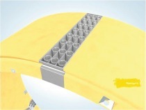
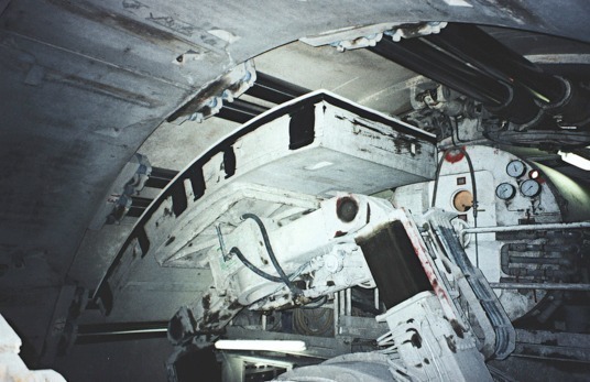
The first applications of monocoque segmental linings took place in Germany for the Munich Underground Section U8/1-7.1 – Fraunhoferstraße with a crossing below the River Isar [2] as well as for the Wil-helmsburg Collector in Ham-burg [3] in 1974. Here the joints were sealed by means of gaskets made of neoprene in the form of compression seals. Tunnels built by the double-shell method with a primary segmental lining such as in the case of the Wandersmann Tunnel (new Cologne-Rhine/Main rail route) or the tunnels for the regional capital of Munich’s drinking water supply, will not be dealt with at length in this report. Fig. 1 displays the installation of segments for a shield drive with the aid of an erector with vacuum suction plate.
Geometry of the segmental Linings
If the ratio of internal diameter to thickness of the segment is taken to assess the “leanness” of a segmental lining the outcome provides values ranging from 9.5 (Kohlbrand Tunnel Hamburg) to 23 (Herren Tunnel Lübeck). The extremely low values of fewer than 15 result from constructional demands relating to the cross-sectional design of the segments especially in the case of small tunnel diameters. The very important form of the groove configuration for watertight segmental linings as well as the essential pressure transference areas in the joints frequently do not permit random reductions in size for the thicknesses of the segments. Conventional ring divisions in Germany amount to between 6 and 9 segments per ring. The number of segments per ring is in this case determined by the length of the segments (in a longitudinal direction) as well as the ratio of the segment length to the segment thickness and the width of the ring. The number of segments per ring diminishes in keeping with smaller tunnel diameters. In addition geometrical reasons, e.g. for transporting segments in the back-ups of the tunnelling installation, govern the size of the segments.
Initially average ring widths of 1.2 m were the standard design in Germany but during the last 20 years ring widths of up to 2 m – especially for large tunnel diameters – have become customary. The clear tendency leading to larger ring widths has largely resulted for economic reasons (greater rates of advance, lower production costs). Furthermore the ring width is restricted by the tunnel diameter and the route radii (ring conicity). Ring widths in excess of 1.5 m thus remain reserved for large tunnel diameters. The development of larger ring widths has ceased at least for the time being both for constructional and technical reasons.
The ring joints during the 1970s and 80s were usually devised with a tongue and groove connection. As from the mid-1990s the cam and pocket connection, which is less prone to being damaged, gained headway in Germany. In solid rock with good bedding for the segmental lining the ring joints were also in an “even” position, i.e. without the rings being interlocked with one another. Examples of this are provided by the Nuremberg Pegnitz Collector, the Katzenberg Tunnel and the New Schlüch-tern Tunnel. The longitudinal joints were generally installed “evenly”. An exception is provided by the longitudinal joints for the keystone, for which interlocking is necessary in order to prevent the keystone being displaced radially following the installation of the ring. In Germany the standard forms are tongue and groove-like interlocking connections. In the 1970s and 80s what are known as cassette segments were applied for building transport tunnels in Germany. However, in 1974 so-called block segments were already applied for the Wilhelmsburg Collector in order to obtain a hydraulically favourable inner side. At the end of the 1980s the more robust block segments ultimately came into their own in Germany.
Cassette segments were sensitive and thus prone to damage especially given high driving forces affecting the bars. Furthermore the wall thickness in the cassette zone of 12.5 cm is regarded as relatively slight for a watertight concrete structure given today’s standards.
In the initial years of application in Germany a lining consisting of left, right and parallel rings predominated, however, since the 1990s an additional parallel ring has been eliminated for economic reasons. At the same time universal rings have been used successfully in Germany. Examples of this are the contract section U5/9-5 of the Munich Underground, contract section 3.1 of the Berlin Underground and currently the Leipzig City Tunnel and the New Schlüchtern Tunnel. Following the successful application of erectors with a vacuum suction plate (e.g. Grauholz Tunnel/CH) for installing segments elsewhere in Europe, this took place for the first time in Germany at the beginning of the 1990s for the Essen urban railway, contraction section 34 and for the Cologne urban railway, contract section M1. Subsequently placing segments by means of a vacuum erector also established itself as an economic method in Germany as well. For installation with a vacuum suction plate all segments possess 2 conic recesses at their centre, into which steel spikes on the erector vacuum plate grip (centering device, security element). Mechanical placing aids in the form of a steel spike and a gripping claw on the erector have only been used in cases of exception in Germany since then especially for tunnels with small diameters (e.g. Pegnitz Collector Nuremberg).
Tunnels with very small route radii are also successfully produced in Germany with monocoque segmental linings. Examples on the transport tunnel sector are the Herren Tunnel with a minimal curved radius of 400 m (road tunnel with 2 lanes), the Düsseldorf Underground, section K-S with a 300 m curved radius (2-track urban rail tunnel) and the Mülheim urban railway, contract section 8 with 200 m curved radius (single-track urban railway tunnel) [4].
Table 2 shows major geometrical characteristics of single-shell, watertight segmental linings in Germany.
Interaction Tunnelling Installation – segmental Lining
In the case of the shield drive with segmental lining both components form an overall system in constructional terms. Although the profile RQ 26t for road tunnels had to be taken into account for both structures, the internal diameter of the Herren Tunnel of 400 m had to be enlarged by 10 cm – on account of the higher lateral incline – owing to the narrower route radii. In addition the equipping of the hydro-shield with 12 thrusting pads as well as 12 retrofitted, additional ancillary jacks for installing the ring was not at all optimal for a segmental ring with a 6 + 1 division and 10.4 m internal diameter. Nonetheless an adapted segment design was developed and successfully applied. The unfavourable marginal conditions for the design of the segments were compensated for by considerably increasing the reinforcement content to 150 kg/m³ for the Herren Tunnel.
In the case of contract section K-S for the Düsseldorf Underground a tunnelling installation was reutilised, which had previously driven a tunnel in Cairo. On account of the French contractors that were involved, the hydro-shield was fitted with 15 thrusting pads. Consequently the customary even (symmetrical) measurement for dividing the segmental lining in Germany with the rings offset by half a segment was not possible. Given the segment design used in Germany at the time the standard elements comprised a circular segment as well as the keystone and the 2 flanking elements together comprising 2 circular segments. In the case of an uneven number of thrusting pads and the rings offset by half a segment on the other hand the flanking elements had to consist of 2 circular segments and the keystone constituting an additional half segment. The flanking elements were enlarged but the pattern of offsetting the rings by half a segment was retained thus catering for a successful adjustment. The keystone in this case was inserted using 2 thrusting pads – in contrast to the customary method applied in Germany.
In the case of the Pegnitz Collector in Nuremberg, a detention tank with 4.4 m internal diameter and in situ concrete dry-weather gutter at its base, a hydro-shield applied for building the London Underground (Jubilee Line Extension, C107) was reutilised. The shield was fitted with 16 thrusting cylinders. Adaptation to the 5 + 1 element segmental lining for the Pegnitz Collector took place by means of a 1/3 element displacement between the individual rings something uncustomary for Germany. The large segments of the ring were in the process each activated by 3 thrusting pads, the keystone by 1 pad.
Reinforcement
A concrete strength class B45 or C35/45 and higher is used as the standard in Germany in accordance with the new generation of standards. With the exception of the first segmental linings produced in the 1970s all segments in Germany are reinforced with structural steel 500. By and large steel bars and to a lesser extent steel mats are made into reinforcement cages. With the exception of a 100 m long test section for the Essen urban railway, contract section 34, so far no steel fibre reinforced segments have been applied for monocoque linings in Germany. In Essen in 1995 60 kg/m³ of steel fibres – Type Dramix ZC 50/6 – were used. Apart from unfavourable marginal conditions, which do not permit steel fibres to be used as the sole reinforcement, this also has to do with a lack of standardisation for steel fibres in Germany. As a result the application of steel fibre reinforced concrete can only be used should approval be granted in each individual case. Innovative reinforcement concepts – such as for instance combined reinforcements consisting of fibre concrete with steel bar reinforcement for added back-up – have so far not been attempted in Germany but are to be anticipated in future.
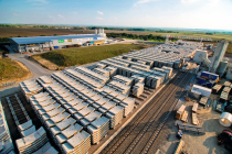
As the selected examples in Table 3 show, in Germany segments contain reinforcement contents varying between 70 and 150 kg/m³. These reinforcement contents are influenced by requirements posed when in service as well as loads imposed particularly during construction, first and foremost the effects of the thrusting cylinders. High reinforcement contents in excess of 120 kg/m³ are often the result of unfavourable effects during construction. An example is provided by the segments for the Herren Tunnel in Lübeck. Fig. 2 displays the production of reinforcement cages for segments taking the example of the Katzenberg Tunnel.
Shield Track Backfilling
When installing the segments in the tail skin a gap, known as the shield track, occurs between the segmental ring and the surrounding rock owing to the process that is applied. The thickness of the shield track amounts to between 12 and 20 cm in the case of tunnels built in Germany. Occasionally even slighter thicknesses, e.g. Hera Hamburg with a thickness of 7.5 cm, have been executed. Such slight thicknesses for the shield track, however, are no longer state of the art. The thickness of the shield track tends to grow as tunnel diameters become larger. In order to ensure the bearing capacity of the segmental lining the shield track has to be completely filled. As a result this is carried out using pumpable cement mortar. Occasionally cement-free “mortars” have been successfully used in Germany with the addition of puzzolane materials – for technical reasons. In the event of breaks in operation in this case stiffening of the cement-bonded mortar is avoided in the delivery lines. The mortar required for backfilling the shield track should at least attain the strength and stiffness properties of the surrounding rock in the case of drives in soft ground. In solid rock if need be low strength and stiffness properties are adequate.
Particularly high demands result in conjunction with the grouting mortar for drives in slightly permeable rock, as the surplus water cannot be filtered off here and the stiffening of the mortar is delayed or there is no grain-to-grain bearing effect. The outcome is that the ring tend to float upwards when it leaves the tail skin as well as the displacement of individual rings, especially when driving small curved radii.
In the 1970s and 80s filling the shield track in Germany was still carried out via plastic valves in the individual segments. Since the 1980s filling the shield track generally is undertaken continuously during the drive through NW 65 mm lines integrated in the tail skin – pressure and volume controlled by means of thick matter pumps. Two-component mortars have so far not been applied in Germany for filling the shield track. On the basis of very promising applications throughout the world, this method seems likely to be used increasingly in Germany as well in future. Purposeful applications can be expected particularly in cohesive soft ground as well as in solid rock.
Static Calculations
The basis for static calculations for segmental linings in Germany has always been represented by the valid technical contractual conditions of individual clients. The essential common feature for planning the vast majority of tunnels were the recommendations for calculating tunnels in soft ground dating back to 1980 [5] as well as the outdated recommendation for calculating shield-driven tunnels from 1973. In this connection an elastically bedded beam largely serves as the static system for operational state. For taking stresses during constructional states into account solution applications from literature for determining the necessary tensile strength reinforcement and during the last few years increasingly FE models have been applied (e.g. disc bearing effect of the segments affected by thrusting forces).
Sealing System
Essentially the segments were produced from watertight concrete (concrete with high water penetration resistance). Sealing the joints basically took place by means of elastomer compression seals.
Up till now more than 2,500 km of joints with elastomer compression seals have been used for waterproofing purposes in Germany. In this country tunnels are scheduled to last for 100 years.
In the case of the 4th Elbe Tunnel Tube in Hamburg and the Katzenberg Tunnel segmental linings were used for the first time in Germany with elastomer compression seals even given water pressures in excess of 5 bar. For the 4th Elbe Tunnel Tube an additional sealing frame was attached to the inner side of the segment (2nd sealing level). Thanks to 4 additional lateral bars per segment longitudinal leaks between the 2 waterproofing levels were prevented.
For the Duisburg urban railway, part-section 7/8A a test stretch comprising 10 segmental rings with an anchored sealing strip made by the Phoenix AG was first tried out in 1998. Although this method using the anchored sealing strips was successful [6], no further seals with anchored sealing strips have been recorded in Germany since then. Table 4 shows selected examples for the application of sealing strips in Germany.
Current pointers relating to the stage reached by joint sealing as well as for testing the sealing strips are contained in the recommendations by the STUVA [7, 8]. The STUVA recommendations have in the interim been included in the ZTV-ING, which are binding for engineering structures under the jurisdiction of the Federal Transport Ministry. Fig. 3 shows the assembly of the elastomer sealing strips to cater for watertightness in the segment joints.
Concluding Remarks
During construction spectacular shield driving installations tend to catch much of the attention; however, this changes once tunnels are completed for only the tunnel linings really leave a permanent impression.
With the Finne railway tunnel (internal diameter 9.60 m) and the Underground U4 link Hafen-city in Hamburg (internal diameter 5.60 m) tunnelling operations for a further 19.2 km of tunnel with single-shell segmental lining began in Germany. With the Wehrhahn Line Düsseldorf, section 1 (internal diameter 8.30 m) and the XFEL x-ray laser tunnel Ham-burg, sections 1 + 2 (internal diameter 4.60 m and 5.40 m) a further 8 km of tunnel have already been commissioned. The start of the tunnelling operations is in each case scheduled for 2010.