Tunnel A2 Maastricht: Groundwater Management with DSI System
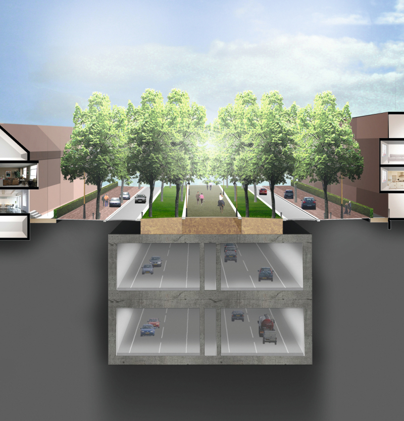
The basis for the A2 Maastricht integration project is represented by an approx. 2,300 m long double-deck tunnel through which 80 % of the present road traffic is to flow. A green and traffic-calmed zone is to be created on the surface.
The Project
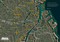
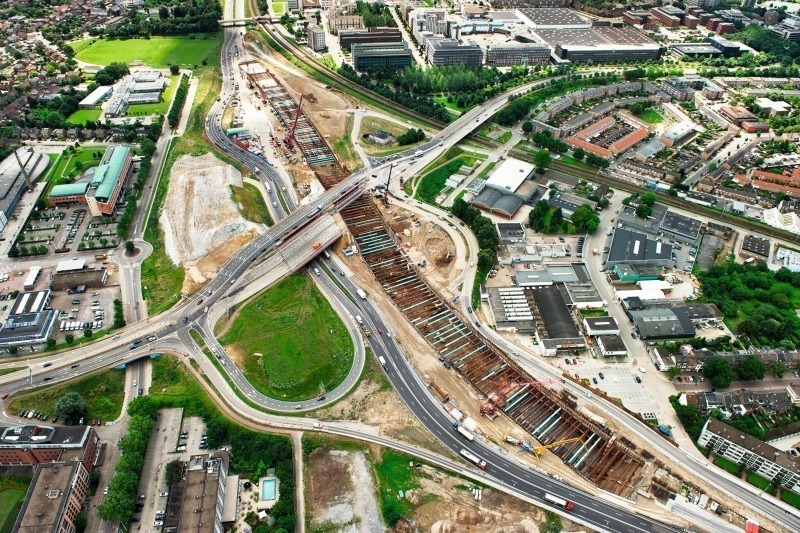
The present A2 reverts to the N2 at Maastricht with the entire road traffic passing through the urban area of Maastricht/NL. Traffic is considerably hampered by the many intersections with traffic lights causing nuisance to local residents and holding up the flow of traffic between the parts of the city. The integration project A2 Maastricht “De Groene Loper” is intended to alter this situation. The core of the project is a roughly 2,300 m long double-deck tunnel through which 80 % of today’s road traffic will flow underground. A green and traffic-calmed zone is to be created on the surface. The project is being planned and executed by the Avenue2 JV comprising Ballast Nedam and Strukton (Fig. 1).
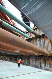
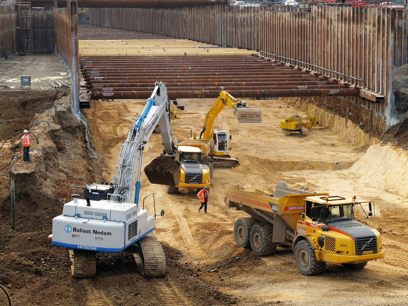
It is intended to build the tunnel by cut-and-cover. The excavation pit itself will be approx. 16 m deep and with a few exceptions 30 m wide. The pit walls will consist of concrete/bentonite diaphragm walls, braced by ties and propping at 3 levels. Groundwater lowering as well as reinfiltration and the entire groundwater management are undertaken by the Dutch subsidiary of the Hölscher Wasserbau GmbH, the Reinders-Wessemius B.V. (Fig. 2).
Ground Structure/
Geology
The composition of the soil in Maastricht, especially for this project, greatly differs from the composition of the soil elsewhere in the Netherlands. An approx. 8 m thick gravel layer is located beneath the surface layer consisting of top soil, clay and loam – roughly 2 to 4 m thick. Underneath there is a fissured limestone layer, which will not be penetrated.
Within the scope of planning the project extensive soil investigations were carried out. Numerous boreholes were drilled and the soil analysed in the lab. Various kinds of probes, seismic tests, trial digs, tracer tests, pump trials etc. were undertaken. All these investigations were aimed at attaining the utmost execution and planning safety at the planning stage.
The soil investigations revealed that there is relatively high uncertainty regarding the strength of the limestone. The stability of the excavation pit walls is largely governed by the strength of the limestone. It was decided to apply the observation method for this project to nonetheless arrive at technically responsible and economically viable planning for the excavation pit. This means that the pit walls are observed during execution by measurements of various kinds so that the bracing of the ground can be improved should previously determined limits be exceeded.
Groundwater
Management System
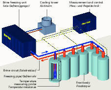
The degree of moisture represented a decisive factor for the strength of the limestone. Dry limestone is substantially stronger than the wet variety. As a result continuous dewatering of the limestone is required to sustain the excavation pit walls. A special monitoring system was established for monitoring the groundwater drainage, which provides the groundwater levels, the water pressure, the amount of water as well as the discharge amount as well as other parameters in real time. If corresponding limit values are exceeded or fallen short of an alarm is triggered via an online system. The Reinders-Wessemius B.V. assures alarm response within 15 minutes.
Setup of the Groundwater Management System
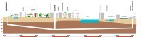
For lowering the groundwater and draining the limestone 520 wells ranging down to 32 m in depth were drilled over the length of the tunnel. The wells were set up in such a manner that they did not have to be modified or adjusted during activities in the tunnel and the necessary bracing of the ties (Fig. 3).
In order to protect the groundwater, the surrounding buildings and the flora and fauna, the pumped ground water had to be reinfiltrated within the direct vicinity of the construction site. Towards this end the Reinders-Wessemius B.V. installed around 1,500 infiltration well points in 14 fields, capable of reinfiltrating some 80 to 100 % of the pumped ground water back into the ground. This involves DSI® technology, which is patented throughout Europe.
Drilling Method
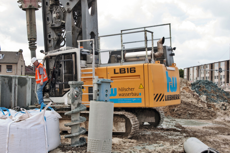
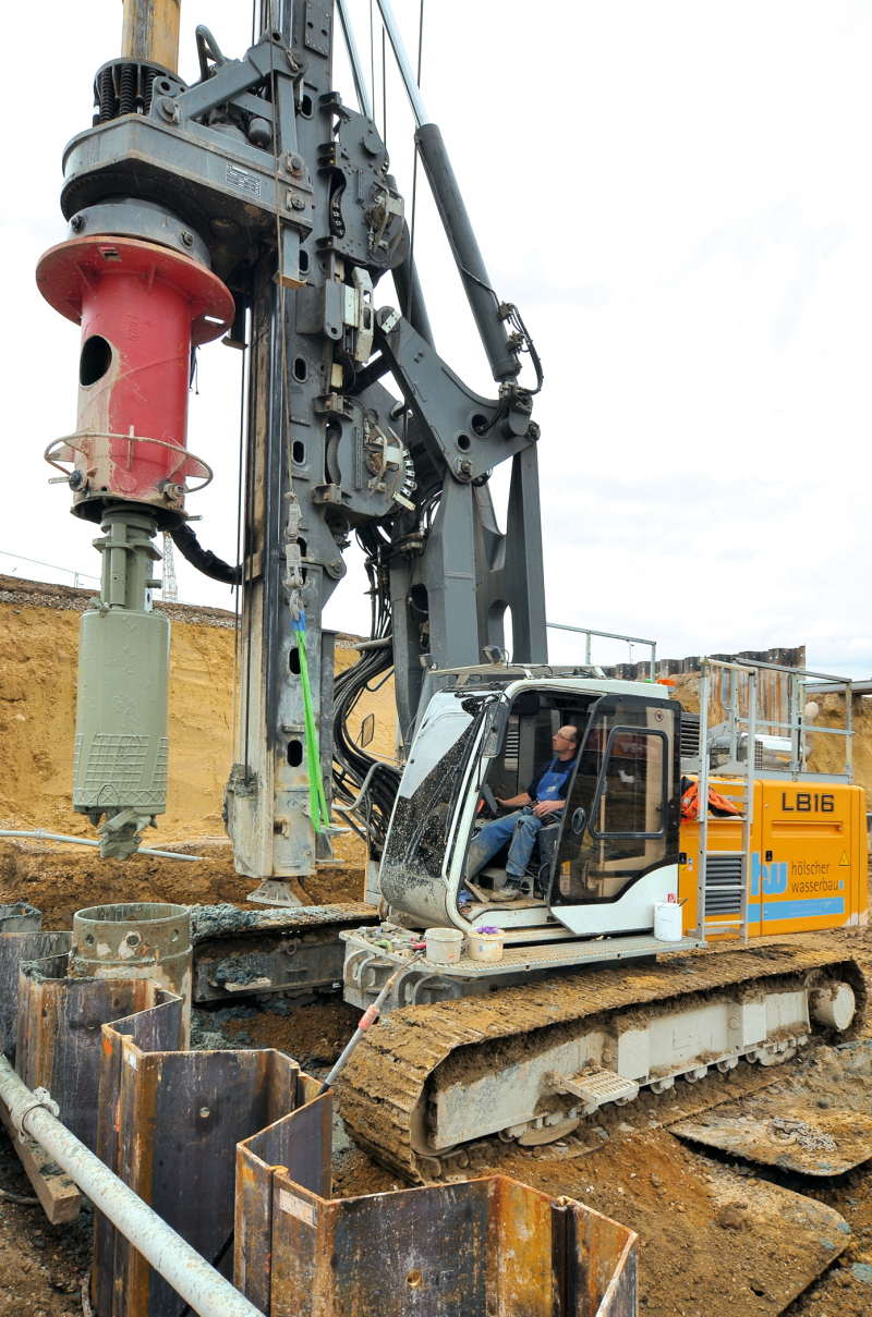
Casing drilling was selected as the method employed. The Liebherr LB 16 deployed by Hölscher Wasserbau is able to produce drillholes with diameters of 1,200 to 2,000 mm depending on the soil with a torque of 16 tm with extended drilling bench (Fig. 4).
750 mm diameter holes were drilled to a depth of 32 m in Maastricht. The solid limestone caused considerable wear to the cutters. Hölscher Wasserbau was able to recover and strengthen the drilling tools in its own workshop in an extremely short time so that no delays resulted from these unforeseen complications.
DSI® System
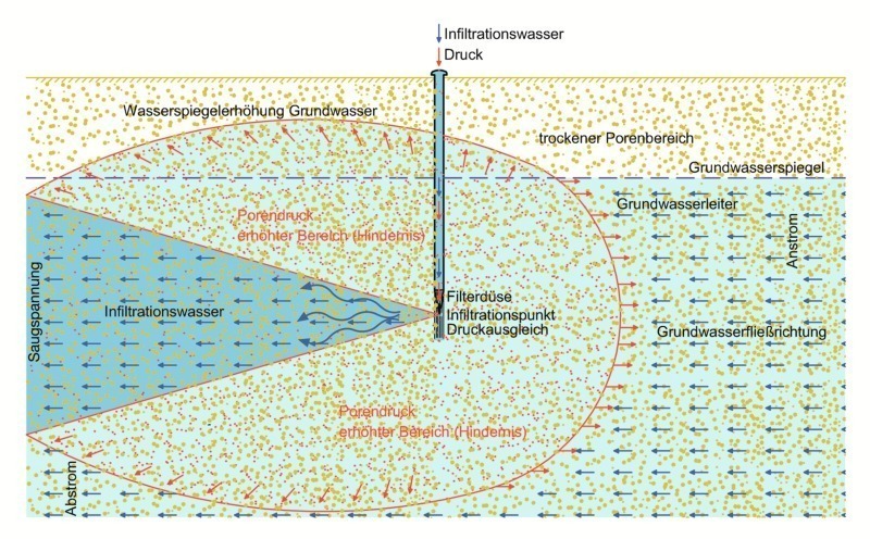
Hölscher Wasserbau holds the patent for the DSI® system (jetsuction infiltration system). This method enables water to be infiltrated into the ground in a substantially more effective and efficient manner. The German geologist Werner Wils has undertaken intensive investigations of these processes in water-bearing soil during recirculation dewatering. He discovered that the heterogeneity and hydraulic resistance of water-bearing soil exert an even greater influence on the infiltration of water than was previously supposed. Together with an infiltration jet a water-bearing soil consists of various infiltration points. These points depend on the local permeability as well as the amount of water to be moved. Both Einstein and Newton describe the “impulse”. An impulse is defined as speed x mass. This results in the following formula for groundwater (Fig. 5):
Groundwater impulse = flow (permeability) [m/sec] x mass [kg]
If water molecules are allowed to encounter already existing water molecules at high speed, a pulsating movement is created. This effect is also known as wave motion. Energy is in fact displaced. This signifies that the infiltration of water is only possible if energy can be transferred. According to the theories by Wils this is solely possible at the so-called infiltration points of a water-bearing soil. The situation for transferring energy is ideal at these infiltration points. This signifies that the complete water-bearing soil as such is unsuitable for infiltration. If one wishes to return a quantity of water back into the soil, then the infiltration point for this quantity of water must first be determined. The groundwater is only transported along its natural direction of flow. This also explains why conventional infiltration wells are applied with varying success and are still applied today. Sometimes an infiltration point is found by chance but sometimes not. Furthermore the infiltration field is not selected according to the groundwater’s direction of flow. For these reasons the absorption capacity of a traditional return source can strongly vary.
DSI® Infiltration
The DSI® system involves determining the correct infiltration point and the method to trigger the impulse. The patented technology is known as DSI® (jet suction infiltration or elementary wave infiltration). Through placing filters at the correct infiltration point favourable surrounding effects are created. As a result the groundwater does not rise in an uncontrollable fashion but flows upwards in keeping with the natural direction of flow. The reason is that the natural groundwater has to bypass the infiltration field as a result of the impulse effect.
In the interim, these tests have been applied in practice on many construction sites with the outcome that less water has to be removed thanks to DSI® being used at a short distance from the site and excavation pit and infiltration functions without any negative effects on the site and pit. This fact indeed entirely contradicts the manner of thinking of modern hydrology. Notwithstanding it can be backed up through examples taken from practice. An extraction system with drainage was established in test fields. Water was pumped out of this drainage system for several days in order to determine just how much lowering is possible. This water was removed via the existing drains. Then a reinfiltration system was installed. 100 % of the water that had been removed was returned to the soil. What became evident was that removal dropped by some 20 % whereas lowering had increased significantly. The groundwater level increased upstream while it dropped downstream.
In the meantime DSI® has been applied at more than 100 sites in Germany and throughout Europe. This also applies to the A2 project in Maastricht. As DSI® can be used and installed very close to the construction site, this test can be carried out practically everywhere especially in downtown areas,
DSI® can be combined with every form of groundwater lowering. The major advantage in this connection is that the proper groundwater lowering method can be chosen in order to protect buildings, flora and fauna. In addition the amount of water to be removed is reduced. Less water removal signifies less water having to be returned. Consequently the environment is less affected.
The DSI® system is being successfully applied in Maastricht. Currently approx. 95 % of the prevailing water is infiltrated. This not only applies to the water from the deep wells but also the water from the public drainage system for the excavation pit.
Summary and Outlook
Groundwater management represents a decisive factor for carrying out the major A2 project in Maastricht. This on the one hand means the safe and efficient lowering and draining of the limestone and on the other the efficient reinfiltration of pumped water to an amount of almost 100 % to protect the existing buildings and the flora and fauna (Fig. 6).
The Hölscher Wasserbau GmbH and its Dutch subsidiary Reinders-Wessemius B.V. provided the necessary know-how for this purpose as well as successfully executing the project by dint of enormous experience.