Special formwork for hydraulic tunnel lining with application of HDPE membrane
To meet the growing necessity of the metropolitan and touristic area of Abu Dhabi, during the year 2008 ADSSC has started the STEP project (Strategic Tunnel Enhancement Programme), which will be completed in the year 2015. For the two key parts of the project T-02 (15 km 5.0 m final diameter tunnel) and T-03 (10.5 km 5.5 m final diameter tunnel) both awarded to the contractor Impregilo S.p.A. (today Salini Impregilo), CIFA has designed and constructed 12 special tunnel steel forms for the loading and traction of the special membrane HDPE (High Density PolyEthylene). This membrane shall be installed before the pouring and integrated with the final lining surface, which has to guarantee over 80 years of useful life of the project under extremely heavy conditions of corrosion.
The Project
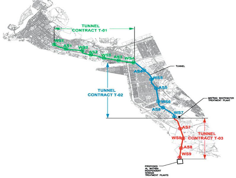
Abu Dhabi Sewerage Service Company (ADSSC) manages for the emirate of Abu Dhabi the whole sewer system of the territory and of the connected islands. They have developed a strategic project called STEP (Strategic Tunnel Enhancement Programme) to be able to control the great residential, touristic and industrial expansions (Fig. 1). This project, through a long network of 41 km of tunnels for the main collector and 43 km of small tunnels as secondary network, intercepts the waste water of the entire urban area of Abu Dhabi and of the new settlements. This new collector and its network will integrate the existing sewerage treatment plant for waste water. Once completed the purification treatment of all waste water, the cleaned water will be transferred again to the urban areas for the irrigation of the green and decorative areas.
This project, which started in the year 2008, is expected to be completed by 2015 and has been divided into three big lots (T01, T02, T03) for the main collector with three final diameters from 4, 5 and 5.5 m, and two lots (LS-01, LS-02) for the small secondary tunnels and the lot of the final Pumping Station (PS-01).
One of the main parts of this project has been awarded to the construction company Impregilo S.p.A., responsible for the excavation and the final lining of the tracks of the main collector T-02 of 15 km (final diameter 5 m) and T-03 of 10.5 km (final diameter 5.5 m).
The starting up of the new collectors will allow the start and completion of a series of secondary projects linked to the new green areas of the city and its tourist attractions already operational and planned.
Impregilo job-site for the Contract T02
Analysing more in detail the main activities foreseen in the first lot awarded to the Italian contractor, we identify three main shafts of dia. 16 m approx. with max. variable depth from 40 to 60 m from the surface. These three shafts called Work Shafts (WS), all located in the mainland south/east area of the city, are identified by the initials WS 5, WS 6 and WS 7. They intercept the main tunnel axis and are used for the lowering and start of the three TBM (Herrenknecht), which have all carried out the excavation in counterslope towards the city.
The TBM lowered from the shaft WS 5, has completed the excavation by going out of WS 4, which belongs to the lot T01, awarded to Samsung. Each track which connects two following work shafts has a length of about 5 km, for a total of 15 km for the whole track of the lot T02.
The excavation of the shafts began in the year 2010. At the beginning of 2011 they enabled the erection and the gradual start of the three TBM, which in spring 2012 completed the excavation of the relevant tracks by reaching a record peak of daily excavation of 45 m.
In the middle of each track of the main tunnel between two work shafts, access shafts of dia. 7 m have been realized. These are located at a distance of a few dozen of meters from the main tunnel axis and are connected with it through a cross passage having the main function of access for maintenance during the operation.
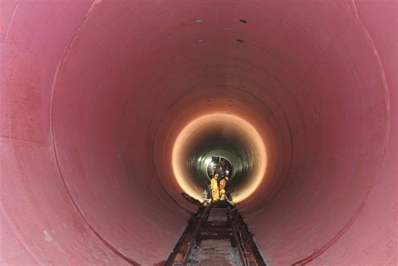
During the excavation the three TBM with diameter 6.40 m have installed a lining with traditional segments in reinforced concrete only with fibers having an internal diameter 5.5 m and thickness of the segments of 280 mm.
Each ring is connected to the next one by special connectors and coupling bars in plastic material.
This primary lining is in direct contact with the highly saline ground water in which the tunnels are realized. Particular care has been given to the choice of cement, so as to minimize the deterioration by chemical attack. Also for this reason, a reinforcement only with fibers has been chosen without using traditional reinforcing cages, which would not be preferable for this severe working conditions.
Final Lining
To ensure a minimum life of 80 years to the work, the designers have foreseen a final lining cast in situ with protection of the surface by means of a high density membrane in polyethylene (HDPE) self-anchoring to the concrete by means of pre-shaped knobs. This membrane covers all the 320 degrees of the cap and shall leave free only the lower 40 degrees of the invert.
On developing the steel form for the casting of the final lining, there were two particularities to consider:
a) The HPDE membrane to be installed on the steel form before the concreting and its pre-tensioning, in order to ensure a perfect anchorage in the concrete;
b) The target productions to be achieved for each of the 6 work fronts of two casts of 12 m for each typical complete cycle.
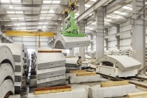
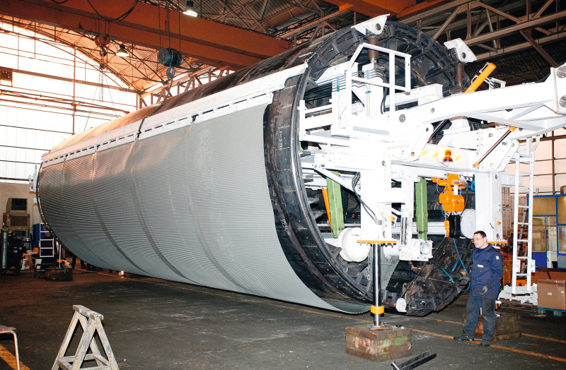
The technicians of CIFA and Impregilo have applied the aforementioned considerations to a solution of formwork which had also to be integrated with the concrete transport and pumping system, as well as with the transport and the loading of the HDPE membrane. The fabrication of the 12 pieces of formwork started in September 2011 and all of them were completed in March 2012.
In December 2011 a functional test on the first fully preassembled formwork system was carried out at the workshop of CIFA, Senago, including a trial membrane loading. Thanks to this test, the setting systems of the membrane, the guide system during the unrolling and the pre-tensioning have been developed and improved, also in cooperation with the technicians of Impregilo and the South African supplier of the HDPE, AKS.
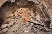
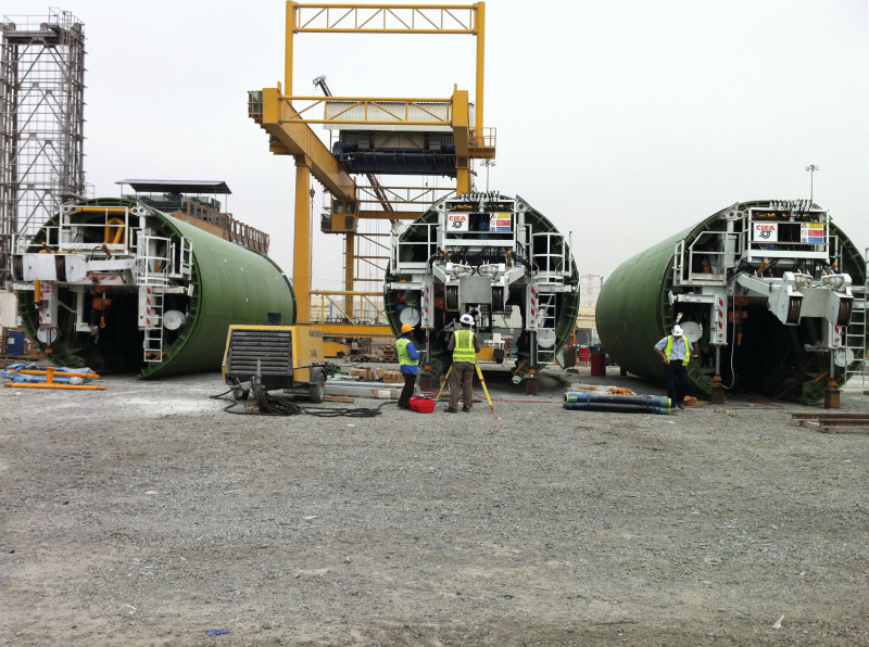
The first steel forms have reached the job-site of the Work Shaft No. 5 in March 2012 and began working on two opposite fronts in May 2012 (Figures 2 + 3).
On each one of the three 5-km-tracks of the lot T02, it is scheduled to proceed with two + two steel forms of 12 m, starting from the access middle tunnel and moving ahead towards their corresponding work shaft. From the same main shafts the supply and transportation of concrete and membrane rolls is provided by means of service rails installed during the excavation.
This scheme requires for the middle WS 5 and WS 6 the simultaneously feeding for the two opposing tracks.
Each pair of steel forms will have to realize the lining of the cap for a track of about 2.5 km of the main tunnel.
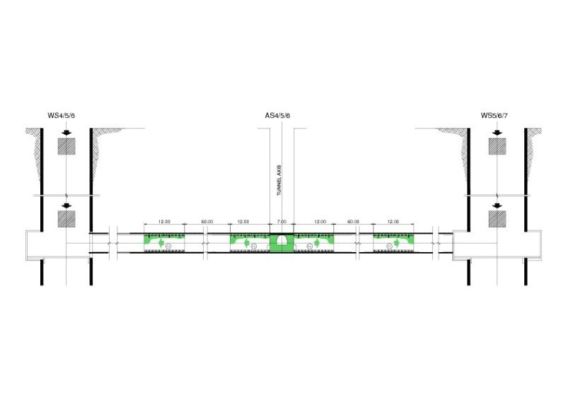
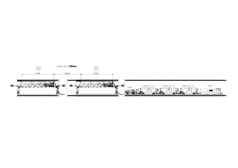
In order to reduce the interferences to the minimum between the two steel forms for the casting and the laying of the HDPE membrane, it was preferred to space the steel forms of 5 concrete casts (60 m) and proceed with the void advancement of the two steel forms at the end of the cycle (Fig. 4).
With this solution, the two steel forms proceed for 4 casts with the classical solution of rear overlapping on the cast already carried out and with front stop-end. The first casting of the front equipment will have a double stop-end. The fifth and final casting of the rear steel form will have a front and rear overlapping on casts already carried out. This final casting requires a particular care, so as to avoid risks due to overpressure of pumping during the final casting or due to the presence of voids for retention of air not properly released for the complete tightness of the joints.
The reduction of these “dangerous” casts to the minimum has been one of the reasons for us to choose this particular casting advancement scheme.
At the end of cycle of the 5+5 casts of 120 m of tunnel, the clearing of the rear invert has to be carried out by removing the rails and by proceeding with the concreting. In this portion of lining, no HDPE membrane is required.
In ideal conditions it could be possible to reach the theoretical advancement of the complete coating of 120 m of tunnel per week (7 working days of 24 hours of continuous work) for each of the six work fronts.
Analysis of an operative cycle
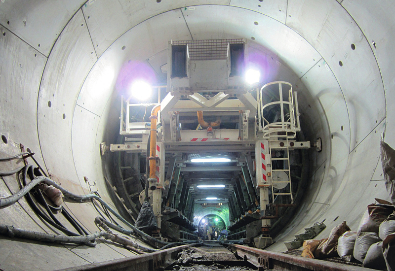
Each equipment is composed of 12 m long articulated steel forms of self-reacting type, which do not require any external anchorage during the concreting. The advancement of the formwork is made by using a proper carrier integrated in the form frame. The carrier longitudinal beam is flanged to two portals at its ends.
Each portal of the carrier is equipped with one system of hydraulic struts for the support and stabilization during the concreting phase. The telescopic legs with the motorized sliding wheels are of tilting type and, once the movements on the rails have been completed, the traveller is substituted by the stabilization hydraulic struts. The legs with wheels are hydraulically rotated upwards and the runway is released for the transit of the trolleys transporting the membrane and of the concreting train.
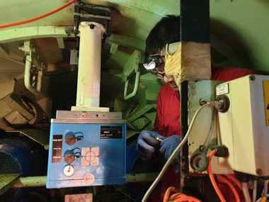
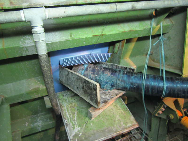
The traveller is equipped with proper double-acting hydraulic jacks for the different movements of the steel form during the setting-up and dismantling.The movement and the loading of the HDPE membrane on the steel form is carried out with integrated systems inside each steel form of 12 m. The membrane arrives up to the inner part of the steel form on service trolleys previously rolled up in externally preassembled elements complete with distribution towing end parts. By means of two electric hoists the whole roll is lifted and loaded on mobile unrolling supports and the transporting trolley travels back to the relevant Work Shaft.
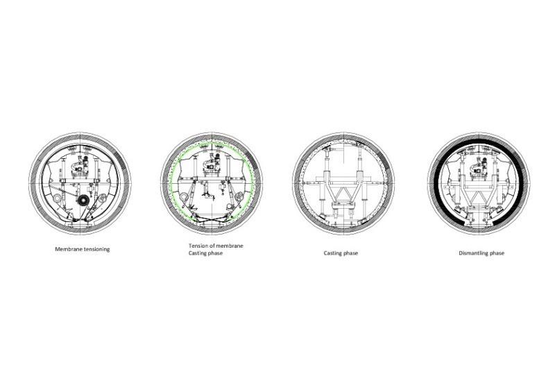
Once the membrane has been properly positioned and by slightly dismantled steel form, the membrane has to be connected to the free end part of the long towing aligner dimensioned and shaped to be able to slide gap between the carried out and the dismantled steel form (max. 85 mm). The towing system of the aligner and the following unrolling of the membrane takes place by two wire ropes operated by two hydraulic winches fixed on the inner face of one of the piers of the formwork. The system of ropes and related guides, integral to the portals, is external to the steel form, to make the maintenance feasible and to control all phases of loading of the membrane. The unrolling of the membrane on the appropriate supports is controlled in the final phase by special adjustable brakes. (Fig. 5)
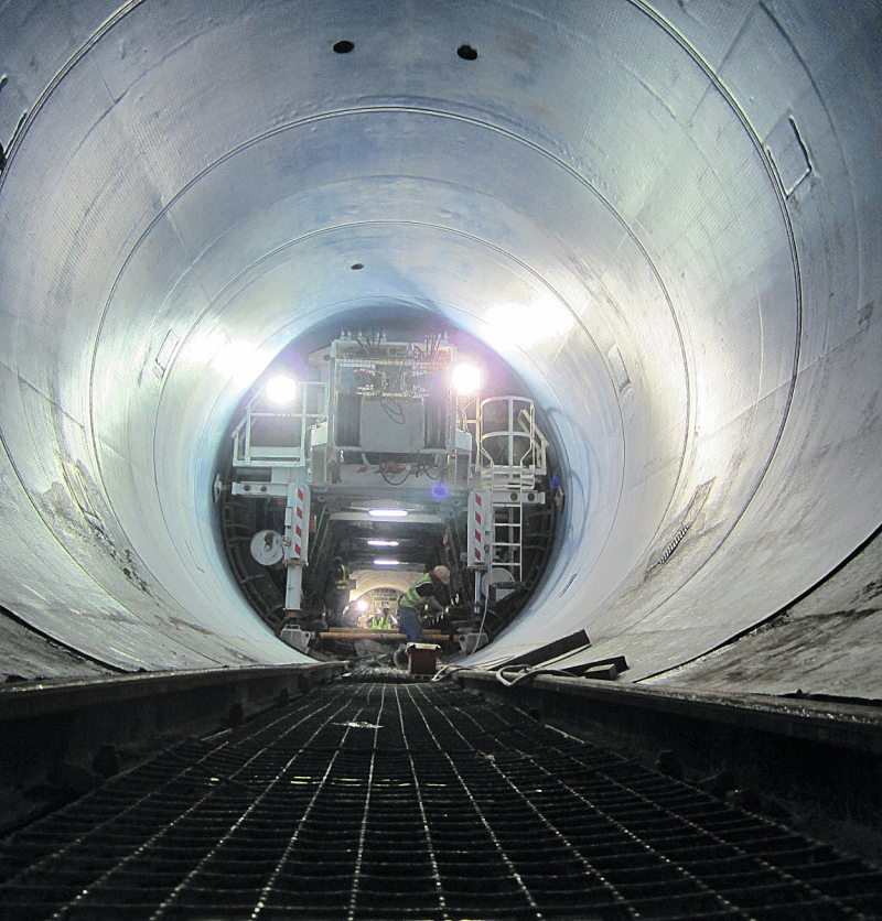
After completing the loading of one element with HDPE membrane 12 m long and 16 m of development, its tensioning on the steel form has to be carried out, which meanwhile has been prepared for the final concreting position (Fig. 6).
For the tensioning, nylon straps rolled on manually operated tensioning devices of the rope properly positioned crosswise are used.
After reaching the correct pre-tensioning of the membrane, the concreting points shall be activated by cutting the membrane on three sides by the side casting doors (usually 2+2 on each side) and of the 4 casting and air release pipes in the cap.
At the front of the steel form the stop-end is realized with shaped panels in plywood which, if necessary, can be transformed into an overlap ring.
After completing the preparation of the steel form, the casting operations can start.
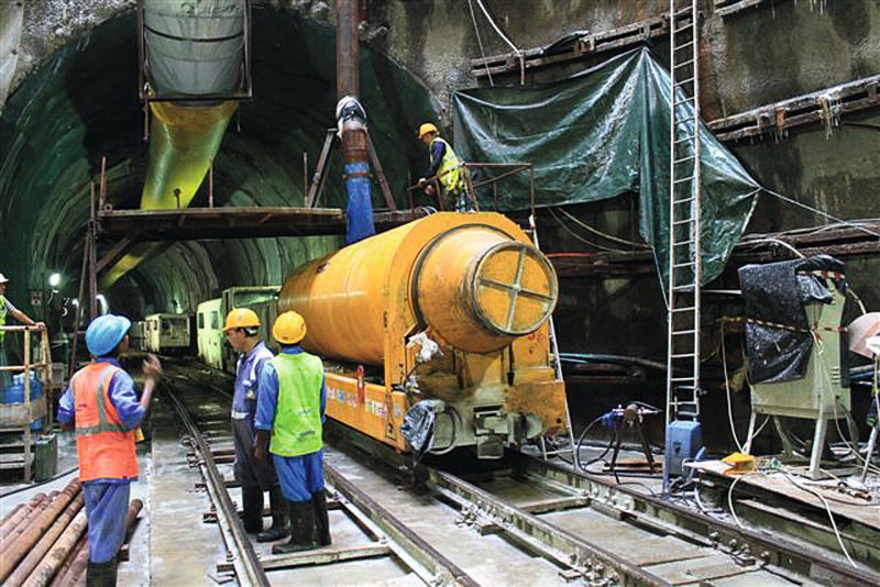
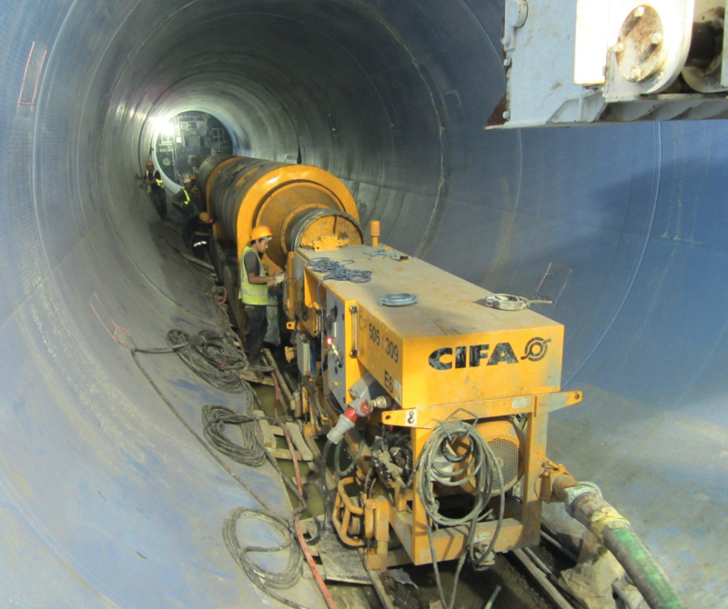
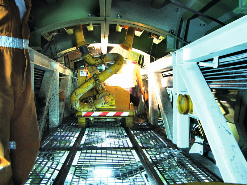
The first concreting train is composed of the concrete pump model CIFA CP 506/309/E6, no. 2 CIFA TrainMix MCA10EI C of 10 cubic meters each, driven by the Schöma-type locomotive (Figures 7 + 8) .
After completing the loading of the train mixers, the train reaches the steel form to be filled in. The concrete pump is then connected with proper articulated pipes to a DCL self-propelled concrete distributor trolley, installed on each formwork. The pouring is carried out in subsequent layers, in compliance with the formwork calculation hypothesis .
The concrete is introduced laterally through the doors with flexible hoses. The doors themselves, before being reached by the level of concrete, are closed after sealing the membrane thermally on the three cut edges. In the cap concrete flows through the casting pipes equipped with guillotine-safety valve, which permits the perfect filling of the formwork. The control of any dangerous concrete overpressure of the structures is ensured by a special valve applied on the pipe of the concreting trolley. (Fig. 9)
After completing the unloading of the first Trainmix (CIFA-Type), the train is divided and, while the pump and the second Trainmix remain operative for the casting, the void one is taken back to the work shaft for the loading and return to the casting position.
In about 4 hours the whole casting operation of 12 m of tunnel is completed, for a total of about 45 m³ of concrete. (Fig. 10)
After 4 hours from the end of the casting, the concrete resistance allows the release of the tensioning system of the membrane. The service rail is thus practicable again to pass through the first steel form under curing and start the dismantling operations and repositioning of the rear formwork with the assembly of one new HDPE membrane roll and then, the final casting.
These are, in brief, all the main manoeuvres linked to the operational phases of the self-propelled steel form. However, a series of operations remain to be carried out which, in several cases, are overlapped, such as: the cleaning of the front invert, the welding and closing of all the holes and the cuts made on the membrane by using proper thermal equipment and the preparation of the longitudinal closures of the invert sector.
As already mentioned above, after completing the 5 + 5 casts of one track of 120 m of concreting of the vault and once the two steel forms have been positioned again in advanced position, the final cleaning of the rear part is carried out and the invert is cast. The concrete feeding is performed with the same train of concrete mixing.
To complete the casting operations, a rear special self-propelled trolley is used to perform the semiautomatic thermo-welding of the transversal joints, which have a systematic step of 12 m. (Fig. 11)
Contract T03
In this lot, the main tunnel, which starts from WS 7 and connects the WS 8 and WS 9 with tracks of about 5 km, has an excavation diameter of 7 m and is being carried out by means of two TBM similar to those used for the T02, which have now left the site for reuse on other job-sites.
For the realization of the final linings of these new tunnels, two new steel forms with diameter of 5.5 m have been planned, designed with the same functional solutions that have to be applied on site starting from the end of January 2013. For the four work fronts foreseen, they will be partly modified with recovery of some major components of the formwork currently working on the T02.
For the transport and the installation of concrete on site the same equipment supplied for the job-site T02 will be employed.
Conclusions
Also this realization has demonstrated that a good cooperation between the construction company of special equipment and the General Contractor allows to overcome the difficulties arising from the new technology, thus achieving the majority of the goals set at the start of the project successfully.
CIFA, Italian Company of Zoomlion Group, which has been operating since 1928 with special equipment for concrete in the field of the underground works, has contributed to this important infrastructural work which IMPREGILO of Milan, one of the major infrastructure Italian contractors, is realizing in one of the countries with the highest rates of investment in the field.
The observance of times and the strict technical requirements of quality and safety have been achieved successfully. This project and its special activities will increase the experience in this field for all the companies and all the people who have participated with their inventiveness.
A special thank to the Project Manager Richard Grahm, the Technical Manager Massimo Franceschi, Mirko Martini of the Technical office Impregilo, with whom several details and solutions have been developed during the construction, and to all the many other expatriates and local workers of IMPREGILO team of Abu Dhabi.