Engineering Innovations for Mix-Shield and EPB Technology for two major Projects in Scandinavia
The report concentrates on engineering innovations in conjunction with mix-shield and EPB technology. It was presented at the 2009 STUVA Conference in Hamburg. These
innovations are displayed on the basis of two major projects in Scandinavia, which are
founded on the given project requirements and experiences gained during tunnelling, which can now be categorised as state of the art.
Two trends have become discernible in the development of mechanised tunnel driving technology in recent years: firstly demands on the engineering technology have risen significantly. Secondly ever more complex challenges have to be mastered regarding the technical and logistical aspects of projects.
Essentially the feasibility of mechanised tunnel driving is governed by the subsoil conditions as well as long tunnel routes given major tunnel cross-sections and ever more frequently even greater groundwater pressures. Surface requirements (densely built-up inner urban areas, constricted space conditions at the access and target shafts) determine the design of tunnelling installations for an increasing number of projects and pose challenges on the construction site logistics.
These future-oriented infrastructural projects call for mature engineering technology that is adapted to growing demands. Thus mix-shields both in their classical operating mode as a shield with fluid-supported face as well as a shield with alternating operating mode, are being used for an ever increasing range of applications. This type of machine has turned out to be a multi-purpose weapon for projects posing high demands by dint of its engineering concept. Parallel to this EBP shields have extended their range of applications thanks to the introduction of foam conditioning and have gained in popularity following successful projects in the Far East in Europe as well. At present EPB shields are also being used for heterogeneous subsoil conditions.
Infrastructural Projects in Scandinavia
Currently 2 major infrastructural projects are being built in Scandinavia: the Malmö City-tunnel and the Hallandsas rail tunnel in Sweden.
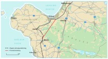
The Malmö Citytunnel is a railway infrastructural project that provides Malmö with a better link to the Öresund Bridge and in turn with the Copenha-gen metropolitan region quite apart from connecting the Swedish railway network more satisfactorily to the entire pan-European high-speed system. The Citytunnel project embraces a 17 km long railway route including two 4.6 km long tunnel tubes within the scope of the project’s biggest contract section E201 driven by mechanised tunnelling technology.
Two 8.6 km long parallel tubes are excavated for the Hallandsas rail tunnel on Swe-den’s west coast. The tunnel constitutes a part of the line connecting Malmö with Göteborg, which is to be developed as a high-speed route. A mix-shield is used for this purpose, which can be converted from open hard rock mode without pressure to a closed fluid-supported system.
The engineering technology applied for these two major projects must master complex subsoil technical and logistical challenges. Towards this end the tunnelling installations were and still are subject to a constant optimisation process so that future construction pro-jects can also be tackled safely and efficiently with engineering technology adapted to the specific project.
Malmö Citytunnel
The twin-bore Malmö Citytunnel is altogether some 6 km long and links the rail route from Denmark approaching via the Öresund Bridge with Malmö Central Station and the Scandi-navian railway network. The overall project consists of 4 individual contract sections E101, E201, E301 and E302. Within the scope of the biggest contract section E201 of the Malmö Citytunnel project two 4.6 km long parallel single-track tubes were excavated with 2 tunnel boring machines.
The contract for planning and executing contract section E201 was awarded in 2004 to the “Malmö Citytunnel Group” (MCG) JV under the leadership of the German company Bilfinger Berger AG, Mannheim and 2 Danish companies, Per Aarsleff and E. Phil & Son A.S.
The two shield-driven 4.6 km long tubes with segmental lining possess a 7.90 m internal diameter. The gap between the tubes varies from 10 to 30 m. The contract for sub-section E201 also involves a 390 m long ramp, a 360 m long cut-and-cover tunnel, the “Triangeln” station (280 m), 4 pressure compensation shafts and 2 emergency exit shafts as well as 13 cross-passages.
The construction of the parallel bores created by mechanised tunnel driving is dealt with in particular.
The tubes were driven at a depth varying from roughly 20 to 25 m. The prevailing formations consist of a 6 to 12 m thick quaternary covering layer set on a roughly 60 m thick zone of tertiary limestones, which possess varying thicknesses. The border area between the covering layer and the rock was characterised as weathered and thus strongly water-bearing.
Two identical EPB shields, each 120 m long with 8.89 m diameter and geared to the geology were applied. The machines were devised for the prevailing groundwater pressures in Malmö of up to 2.0 bar. The first shield started from “Holma” station at km 5+320 towards the target “Malmö C” at km 0+448 at the end of November 2006; the second EPB shield began excavating in January 2007.
The cutting wheel was adjusted to the expected geological conditions and fitted with an electric drive. It was equipped with 124 cutters, 46 single discs (17”), 4 double discs (17”) and
16 buckets. All the tools can be replaced safely and efficiently from the rear of the cutting wheel.
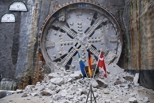
After excavating 2.7 km up to Triangeln station the first machine reached its first stage target after 9 months. In the “Triangeln” station the machine was pulled through the 280 m long structure and overhauled there in order to drive the remaining 1.9 km towards the “Malmö C” (Malmö Central) target shaft. In March and April 2008 the 2 machines reached their goal “Malmö C” with rates of advance of up to 239 m per week (Fig. 1).
The tunnel with 7.90 m internal diameter was lined with watertight reinforced concrete segments. A uni-ring with a smooth annular joint and guide rods was applied in the longitudinal joints. Intermediate layers in the level annular joints and bolting of the segments in the longitudinal joints were not foreseen apart from at the key-stone. The 1.8 m long segmental ring was produced using
7+1 elements. The segments weigh 5 to 6 t with the key-stone weighing 1 t.
The segment factory was set up in Holma across from the tunnel portal.
The total of 13 cross-passages required for the altogether 4.6 km long twin-tube tunnel were produced as the TBM drive progressed. Base segments were installed in the back-up’s rear zone, which enabled a two-track operation in the tunnel. During the drive it is thus possible to create the cross-passages joining the 2 tunnel bores. The dimensions of the elements made it possible to set up a passby siding that was required locally in addition to the central track. This could be swivelled at the same height.
The track ensured that the machine was supplied with segments and driving material in addition to transporting personnel.
Hallandsas Railway Tunnel
Currently the rail link between Malmö and Göteborg is being developed as a high-speed route on the Swedish west coast. When the new twin-track rail link for high-speed trains is concluded and put into service the travelling time between the 2 cities will be cut by 2 hours. In addition the total capacity of the rail link will be increased from 4 to 24 trains per hour.
One challenge along this route is posed by crossing the Hallandsas range to the south of Bastad, towards which end a convertible mix-shield with 10.6 m diameter is being applied.
Initial attempts to drive the tunnel by mining means were thwarted in the mid-1990s owing to geological conditions that were difficult to master such as high water pressures and inflowing water as well as strongly fissured rock.
Bids were once again invited for the project requiring a 9.4 m internal diameter for the 5.5 km long tunnel preferably using mechanised tunnelling technology. Owing to the attempts that had previously failed strict environmental requirements especially regarding the groundwater were laid down.
The Swedish Central Office for Railways (Banverket) is the client for the project. A Swedish-French consortium Skanska-Vinci was awarded the contract to accomplish the project.
The prevailing geological formations along the planned tunnel route mainly consist of gneiss with amphibolite intrusions. The uni-axial compressive strengths of the freshly exposed rock can be as much as 250 MPa; the Cerchar abrasiveness index (CAI) generally lies in excess of 4.5, with values of up to 5.9 recorded. As a consequence the rocks are classified as being extremely abrasive.
The groundwater pressure at tunnel level reaches 13 bar. Consequently the greatest challenges for mechanised driving in the case of the Hallandsas project are posed by expected high water inflows and at the same strict legal limitation of the permissible withdrawal quantities. In addition encountering limited fault zones with soft ground and similar conditions was not precluded.
Against this background initial conceptional developments were undertaken at Herren-knecht based on the main requirements dating from 1999/ 2000. The project at this point in time was still at the preliminary tendering phase. Technology had to adapt to the following requirements:
– Removal of hard and abrasive rock formations
– Removal of soft ground or mixed face conditions
– Danger of penetration of large quantities of water along the entire tunnel route
– More than 10 bar static water pressure along the bulk of the tunnel route
– Strict (legal) environmental conditions governing the amount of inflowing water
– Strict environmental conditions and approval procedures for the materials and methods applied.
It soon became evident that only a shield machine with sealed tunnel lining (segments) would be able to completely comply with these requirements in the event of a mechanised tunnelling solution. The TBM had to be capable of performing both in an open and closed driving mode so that the most unfavourable geological and construction technical conditions such as maximum water pressures and complex rock conditions could be safety mastered. The fluid-supported mode thus represented the sole possible option for the closed mode.
In January 2004 Herren-knecht was commissioned to supply a tunnelling machine commensurate with the requirements (Table). Taking into consideration that excavation by the closed mode under high pressure given hard rock and mixed conditions at the face represents the most difficult operating mode, extensive possibilities for measures designed to stabilise the subsoil from inside the machine had to be integrated so that operation in open mode was supported. The following operating modes are available for such a concept involving a dual-mode mix-shield for hard rock (Fig. 2):
– Open mode with dry, primary material removal (TBM belt conveyor)
– Open mode with (cyclical) measures designed to stabilise the subsoil (advance grouting)
– Open mode with (cyclical) measures designed to stabilise the subsoil under closed static conditions
– Closed mode with hydraulic (slurry) conveyance system with reduced pressure at the face
– Closed mode with full pressure at the face allowing active face support.
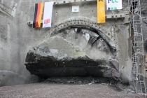
For the tunnelling machine used for the Hallandsas project it was essential that it can be operated with 13 bar supporting pressure and that the chambers can be entered by means of saturation diving given high pressure conditions. In this way the machine is completely furnished for extraction in the open hard rock mode with a single shield TBM as well as for excavating in slurry operation in closed mode with active face support up to a maximum dynamic pressure of 13 bar (Fig. 3).
The Hallandsas tunnel project with a history now stretching back for more than 15 years represents one of the most sophisticated tunnel projects currently under construction. By mid-2009 the construction consortium’s teams excavated more than 4,300 m in tricky water-bearing rock formations with a convertible mix-shield for hard rock and produced a dry tunnel lined with segments. No further ecological problems occurred and the general public’s acceptance of the structure was rekindled to a large degree. Essential for the success of this project has been the close, well-focused partnership and collaboration among all the parties involved – the client, the contractor and the machine manufacturer.
Conclusion
The 2 major projects in Sweden distinctly spotlight the demands posed on today’s tunnelling projects. This particularly relates to the challenges concerning the applied tunnel driving technology – geared to the complex geological subsoil conditions – as well as executing the project.
The described types of machine possess a potential for innovation as far as their geological and hydrogeological range of application is concerned. The mastering of extremely sophisticated conditions for soft ground drives and in hard rock with varying face conditions, rock of high compressive strength and wear intensity as well as high inflows of water and high water pressures calls for a machine design geared to the subsoil conditions.
The machines applied in the above-mentioned projects comply with the demands placed on mechanised driving and exemplify the high standard of innovation arrived at nowadays. Thanks to the findings obtained during driving invaluable impulses are provided for future follow-up tunnel drives and extensive detailed improvements described, which are trail-blazing as far as the design, the further development, the construction and pending excavation are concerned.