Two Earth Pressure Balance Shields for Metro Line A Extension of Prague Metro
Since mid of 2011 two Earth Pressure Balance Shields are employed for the extension of Metro Line A in Prague. The tunnelling progress documents the efficiency of the employed technology facing challenging conditions of settlement controlled inner-city tunnel construction.
1 Introduction
Prague is the capital and also largest city of the Czech Republic. An important part of the public transportation system is the Prague Metro. The public transportation network comprises currently 3 lines of about 60 km of tracks running mostly underground and 57 stations. The current lines are Line A, running east to west from Depo Hostivař to Dejvická, Line B, running east to west from Černý most to Zličín and Line C running from north to south from Letňany to Háje. The metro is the fastest transportation system around the city. It serves about 1.5 million passengers a day and is thus one of the busiest metro systems in Europe.
The Prague Metro system is designed as a triangle, with all 3 lines meeting in the center of the city at 3 interchange stations. At the start of metro construction in Prague in the 1960s with Russian made open tunnelling shields, the cast iron lining was used. Later the concrete segments replaced the cast iron completely. In the seventies of the last century 2 TBMs with extruded concrete lining bored part of the Metro Line A under the Vltava River.
The project to focus on in this paper is the metro extension of Line A, which is being constructed between station Dejvická via Červený vrch, Veleslavín, Petřiny and all the way out to Motol. The extension of Metro Line A was set as a priority by the municipal government in the development of the metro network, with exclusive rights to finances obtainable from European funds. A contribution of Line A extension will be to ease the situation on Vítězne square by cutting the number of buses by up to 50 % with a positive environmental impact and furthermore to improve the traffic situation in the north western part of Prague. Also, the southwest part of the city will get new traffic connections. The next step will then be the planned north-western extension of Line A towards Ruzyně Airport.
2 Extension of Metro Line A from Dejvická to Motol
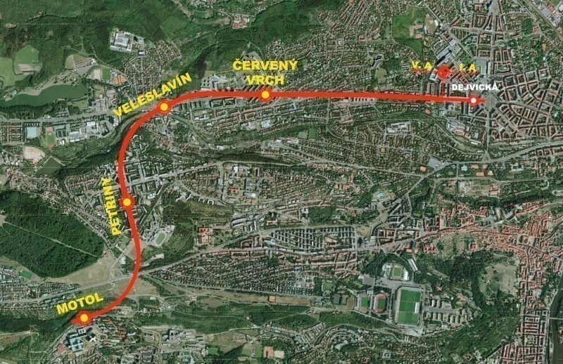
The companies Metrostav and Hochtief CZ have been commissioned to build the about 5.7 km long extension of Metro Line A starting at Dejvická to Motol Station. Three new intermediate stations will be built at Cerveny Vrch, Veleslavin and Petriny. The new metro line will serve the large residential area of Prague 6 to provide a quality transport service for the biggest hospital complex in Prague (Fig. 1).
The morphology of the terrain and the high degree of urbanization affected the choice of tunnelling method for the planned alignment. For almost the entire extent of the project mechanized tunnelling technology is applied. The 5.7 km are excavated and lined by using two 6.1 m diameter EBP Shields from Herrenknecht (S-609 and S-610) for the 2 single-track tunnels from Vítězné Square to Motol. Three of the new Metro Stations (Cerveny Vrch, Veleslavin and Petriny) are mined, while Motol station is built by cut-and-cover method.
The EPB Shields have been designed to suit the prevailing geological conditions, which have been predicted along the designed tunnel alignment. The geology is mainly characterized by clay shale rock types and their weathering products. Besides the clay shale, a greater amount of sandstone, siltstone and claystone as of different soil types (mostly of clayey character) were expected and encountered during drives completed to the end of 2011. Along the tunnel alignment both, stable and unstable tunnel face conditions, as well as mixed face conditions are predicted.
3 TBM main data
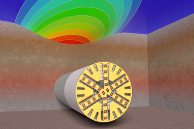
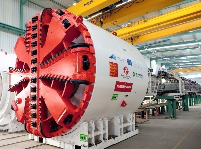
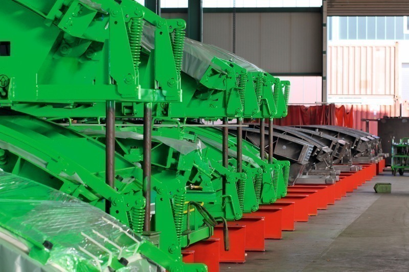
The EPB Shields for Metro Prague are equipped with a hydraulic main drive powered with a total of 1,200 kW. When tunnelling, 32 thrust cylinders apply a nominal thrust force of about 39,000 kN. The cutting wheel is equipped for both directions of rotation. It is designed with an opening ratio of 30 % and fitted with 38 pieces of 17-inch disc cutters of 100 mm spacing, 64 cutting knifes and 8 buckets. The cutter heads were fitted with ripper tools for the start of boring. Two hydraulic wear detection units are installed for the soft ground tools and buckets (Fig. 2).
The 2 machines, which were supplied to Metrostav a.s. for the extension of Metro Line A in Prague have a total length of 96 m. The 87 m long back-up comprises 7 gantries and a bridge construction. It houses all the logistics equipment needed to operate the entire system.
During shield drives in un-stable ground, face support pressure is generated to counteract any loss of stability at the tunnel face. On an Earth Pressure Balance Shield, the soil excavated by the cutting wheel is used to support the tunnel face. During advance in full mode, the excavation chamber is permanently completely filled, preventing settlement on the surface. To achieve a state of balance, the face support pressure is transmitted from the hydraulic thrust cylinders to the conditioned, loose soil through the bulkhead. The internal stators and rotors cut through the soil mixture, while foam can be injected via nozzles to ensure that the required consistency is maintained. There are in total 4 foam units installed in the cutting wheel, 4 stators for foam in the excavation chamber and 2 x 3 foam injection points at the screw conveyor. The screw conveyor removes the treated soil from the invert area of the excavation chamber and hands it over to a conveyor belt. The speed of rotation of the screw conveyor regulates the volume of soil removed from the excavation chamber and adjusts it to the advance speed. The aim is to keep a balance between the volume of soil removed by the screw conveyor and the volume of soil being produced by the advance of the EPB Shield. This makes it possible to ensure optimal support of the tunnel face.
The key information consisting of all relevant tunnelling parameters is fed into the central control cabin where it is visualized on screens for the TBM operator. The operator monitors the largely automated processes and takes corrective action when needed. This is important especially in the urban area of Prague where tunnelling demands for a settlement controlled tunnelling process.
To meet the challenges of tunnelling in constraint areas, the EPB Shields are equipped with
• a hydraulic wear detection system for an efficient excavation process and to avoid damage to the tools and the steel structure of the cutting wheel and
• an extensive data acquisition system that gives continuously information about the support of the tunnel face and many further machine parameters essential for a controlled excavation process.
The EPB Shields are equipped with injection drill rigs for ground stabilization measures in the tunnel crown and tunnel face area in the case of instable tunnel face conditions. Via 8 inclined injection lines of a nominal diameter of 100 mm it is possible to perform crown injections with an angle of 14° and 2 horizontal drills enable injections into the tunnel face. The installed drilling rigs will be also used for probing ahead of the face in some cases, one of them might be the area around Červený vrch, where the tunnel alignment crosses the former mining fields (iron ore, mining started in 1860).
4 Control Boring Process System (CBP)
The demand of a settlement controlled operation played an important role during the design phase of the TBMs, therefore, a control system was installed that records and analyzes settlement relevant data such as for example the support pressure and annular gap backfilling. The recorded values will be compared with reference and tolerance data defined by the operating authority. With this safety system, the so called Controlled Boring Process (CBP), frequently changing geological and hydrological conditions with low overburden can be technically mastered. The CBP aims to combine information on possible settlement or heave measured above the tunnel route with all relevant operational data of the TBM in order to facilitate the development of even more sensitive tunnelling strategies and, in terms of risk avoidance, to continuously optimize the tunnel excavation. First, in a kind of tunnel excavation record, data of the tunnel route, for example with regard to settlement measurements conducted above ground and geology, are related to essential operational data of the TBM. Based on this, target values and tolerances for operational parameters of the TBM relevant to the settlement can be established. These values and tolerances are defined by the shift engineer for the machine operator and are visualized on the individual machine data displays in the control cabin. They can be adjusted to respond to current measuring results at all times if necessary. Furthermore, all specific parameters are recorded during the entire excavation to enable a comprehensive analysis of the tunnelling performance with regard to the control of settlement.
At the end of year 2011, the second machine, S-610 (named Adela), followed the first machine’s (S-609, named Tonda by children from Motol hospital) successful excavation under the residential complex, where a maximum settlement of only 6 mm was allowed. Continuous monitoring of the complex structures and using of CPB system contributed to the trouble-free passage of both machines, complying with strict request of minimum settlement.
5 Two-component grouting
In order to keep settlements controlled an effective annular gap backfilling system is required. The EPB Shields for the Metro Prague are designed with a two-component annular gap backfilling system comprising 4 injection lines. Component A can be described as a stabilized main component consisting of water, bentonite, cement and a stabilizer and component B as the activating component of the system consisting of a sodium silicate. Characteristic for the two-component backfill material is an early strength development which is advantageous in order to stabilize the bond between the excavated surface and the tunnel lining. By this, displacements of the rings when they are stressed, for example, by back-up loads can be prevented. The two-component grouts are generally composed of water, bentonite, cement, a stabilizer and an accelerator. The use of two-component grout provides greater flexibility in varying the ratio of the 2 components A and B. When mixed, the 2 components react within a short time (within minutes) to a gel which begins to solidify afterwards. The setting time of the suspension can be varied and hence the extent to which the mix will penetrate the ground. The main advantage of the two-component system are the quick stabilization of the ring due to a short time to reach sufficient strength and the working properties of the grout which are independent of idle times or advance speed and the pumpability over longer distances.
6 Segmental lining
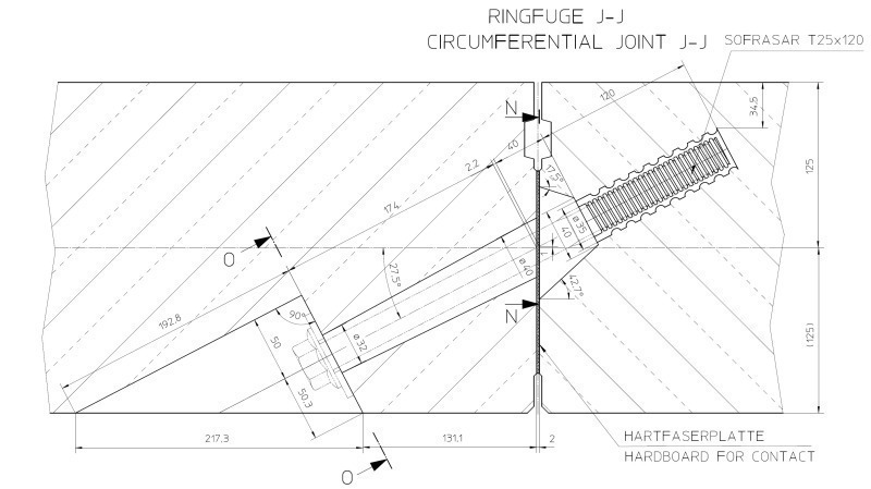
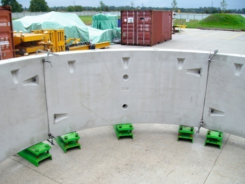
The tunnel is lined by reinforced concrete segments. One tunnel ring is composed of 5+1 segments and has a length of 1.5 m. The geometrical design of the segments, produced in high-precision moulds delivered by Herrenknecht Formwork, considers all loads as water pressure, soil conditions and all situations of producing, transporting and erecting in the tunnel. According to the designers experience for such diameters and ground conditions a Universal-Ring (both side tapered) was chosen. The segments are equipped with EPDM-gaskets (M385 69 Portland, PDT) and are bolted during installation both in the circumferential and longitudinal joints (Fig. 3).
The radial joints are equipped with hardboards (ply wood). To proof the right dimensions of the segments and hence the complete ring, a trial ring was casted, erected and measured in the manufacturers workshop (Fig. 4).
The segments for the Metro Prague are manufactured in Senec by the company Doprastav. Considering the manufacturer’s requirements a stationary production was the preferable solution. The 9 sets of moulds (54 moulds) were casted in year 2011 once a day. To gain a high workability and durability of the segment concrete the manufacturer ran tests in the lab and did several trial casts (Fig. 5).
These prefabricated reinforced concrete elements are taken into the tunnel on carriages. At the front end of the carriage, the segments are individually raised by a special transfer crane and placed on the segment feeder, which brings the segments to the front area of the tunnel. Here, the segments are lifted by vacuum plates on the erector – a hydraulically controlled crane arm – and moved into place.
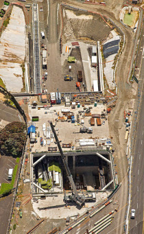
7 Progress on site
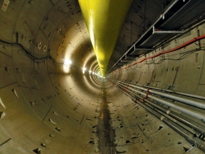
The machines were assembled in the Herrenknecht workshop in Germany where the main components were tested and then transported to Prague. Tunnelling started mid April 2011 (S-609) and mid July 2011 (S-610). The jobsites’ tunnelling crews have advanced the 2 machines 1,500 m (S-609) and 1,150 m (S-610) until December 2011 with weekly best rates of up to 162 m (S-609) (Fig. 6). After accomplishing the excavation of the 2 parallel single-track running tunnels by the end of 2012, the TBMs will be recovered backwards through the tunnel.
8 Conclusion
The progress of both machines until the end of 2011 shows great potential of application of TBM technology for the future development of Prague Metro. For the new Line D, which is in planning stages, the experience gained during construction of Metro A Line Extension is important and could bring savings in terms of cost and time.