Segmental Ring Design – New Challenges with High Tunnel Diameters

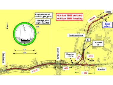
![Internal Forces N [kN/m], M [kNm/m] and Deformations [mm]](https://www.tunnel-online.info/imgs/100839954_92a37b519f.jpg)
The Article was held on the 38th Annual Meeting of the International Tunnelling and Underground Space Association and the World Tunnel Congress 2012 in Bangkok/Thailand. It was the third lecture in memory of Sir Alan Muir-Wood presented as the Muir-Wood lecture and it is a very great decoration for the speaker.
1 Introduction
Tunnel lining with segmental rings behind TBMs are reinforced concrete elements and must be calculated and designed according to the standards of reinforced concrete constructions. In tunnelling, however, specific circumstances must be taken in account, which make design much more complicated: The determination of loads during ring erection, advance of the TBM, earth pressure and bedding of the articulated ring, is difficult. The ring model and the design input values must be studied carefully according to the parameters of the surrounding soil.
For utility tunnels and single rail track Metro tunnels, where the ring diameter is smaller than about 8 m, the parameters may be chosen on the “safe side”, for example, the full cover can be taken as external load. For bigger tunnel diameters, more realistic soil parameters must be found and inserted in the structural design, otherwise it may be impossible to verify the tunnel lining.
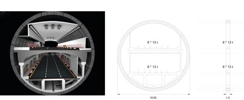
Several tunnels with about 15 m external diameter were already built with success. Tunnels and caverns with an diameter near 19 m, with primary shotcrete lining and concrete inner lining, were executed on several projects, too. Now a new project, the Orlovski-Tunnel in St. Petersburg, with an outer diameter of 18.65 m in a non-uniform soft soil strata, is in the design phase. The diameter corresponds to the height of a 6 floor building (Fig. 1).
2 Project description
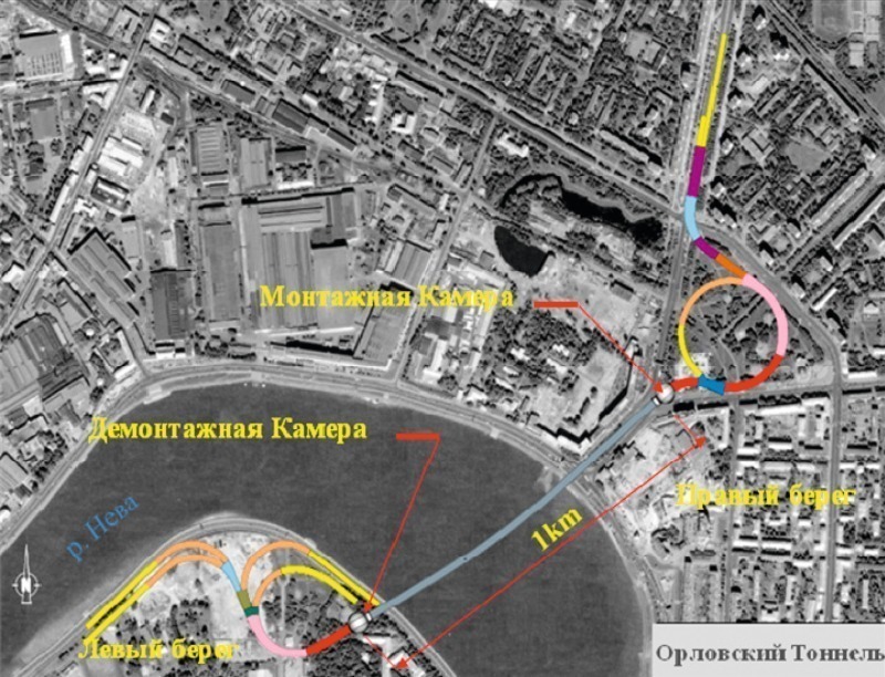
The Neva river crosses St. Petersburg from the Baltic Sea to the harbour area east of the city and the Ladoga lake. All balance bridges are opened at certain hours, mostly during night time, to allow bigger ships coming over the Baltic Sea to reach the harbour (Fig. 2). During these periods, the Neva cannot be crossed.
The „Orlovski-Tunnel“ would improve the traffic situation reasonably, and connect the separated city areas around the clock. Bridges could be held open for longer periods and improve the continuously growing ship traffic (Fig. 3). It is planned, to build the tunnel as a „Public-Private-Partnership“ project. The building costs of approx. 1.4 Billion Euro should be refinanced by tolls.
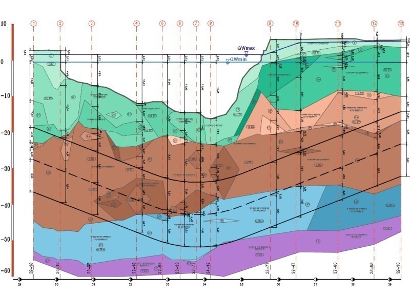
2.1 Geology
The geology in the area of the Neva-crossing consists of quaternary soils, deposed by rivers during melting of the nordic glaciers at the end of the last ice age. Caused by several advances of the glaciers, the underground is partly over consolidated. The strata is shown on the geological section (Fig. 4). The soil parameters in the area and above the tunnel show a very soft ground. The clayey, silty fine sands have a dead weight of γ ≈ 20 kN/m³, a Young‘s modulus E ≈ 10 to 30 MN/m², a Poisson‘s ratio ν ≈ 0,3 to 0,4, a φ ≈ 20° and a cohesion c ≈ 15 kN/m².
3 Determination of Loads
3.1 Earth Pressure
If a tunnel has an overburden of less than 2 times the diameter, the full primary earth usually is inserted in the calculations. A reduction of the earth pressure, e.g. by using the Terzaghi theory, often is not allowed for the final state. Calculating the 22 m overburden, the maximal vertical load would be near 440 kN/m².
Finite Element calculations show, that a load reduction of approx. 25 % should be possible. This corresponds with the Terzaghi reduction. This reduced vertical earth pressure was used for the calculations. The full cover was calculated with reduced safety factors.
For huge diameter tunnels with segmental lining, a marginal change of side pressure leads to notable changes of ring bending moments. The side pressure in most of all projects is determined by the soil angle of internal friction k0 (k0= 1 - sin φ‘).
Measurements to determine the side pressure factor k0 are difficult and need elaborated instrumentation and interpretation. For the Orlovski project the calculated k0 varies from 0.6 to 0.75. Because of possible over consolidation, a maximal k0 = 1.0 was calculated, too. Higher values are not realistic, as small soil deformations already lower the k0-factor under 1.0.
For control calculations with a 2 dimensional Finite Element Method (FEM), the release factor at the tunnel face must be calculated, too. If ground deformations must be limited, the small factor is used. This means, the slurry pressure in the cutting chamber must be high, more than 0.5 bar over the water pressure in the top area of the TBM. Only a small stress release in the ground is possible, the load on the segments is high, ground deformations are low. If higher ground settlements can be accepted, the slurry pressure can be lowered up to water pressure at the face. As a redistribution of loads around the tunnel is possible, a high release factor was chosen to calculate the maximal settlements. The earth loads on the lining lowers down to a minimum. For this case, the grouting pressure around the segmental lining may give the maximal load on the ring. Because of uncertain input values, the parameter studies were necessary to find a realistic load determination and to understand the specific interaction between surrounding soil and segmental lining.
3.2 Loads during Ring Erection and Advance
Segments already get considerable loads already during transport and ring erection. They are pulled out of the formwork when concrete hardening is in an early stage, and the segments are manipulated during stocking, transport, ring erection and advance. For the dimensioning of reinforcement, the loads during advance are often decisive.
Big tunnel diameters need big TBMs to excavate the tunnel. The foreseen slurry TBM with an excavation diameter of 19.2 m will has 37 double rams with about 7’000 kN advance force, each. The pressure must be absorbed by the segments in a small circumferential joint area. High tensile splitting forces must be taken by special reinforcement (Fig. 5).
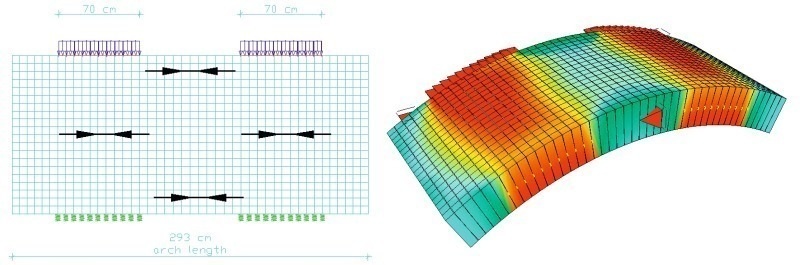
3.3 Loads from Built-in Components and Traffic
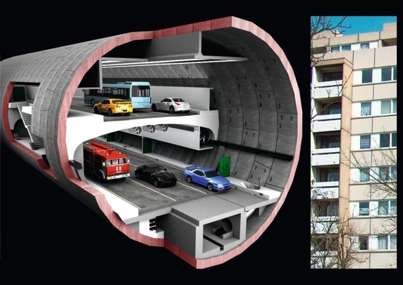
Even in traffic tunnel, the built-in components and traffic loads are not significant for the structural analysis. The multi-level Orlovski-tunnel however, has high traffic loads which are transferred to the segmental lining within small areas (Fig. 6). In the soft soil ground, this may lead to high deformations between the segments and had to be verified in the structural analysis.
4 Bedding Assumptions
The longitudinal joints between the segments of a ring react as articulations. Because of the high normal forces, bending moments can be transferred over the joints, but the stability of the ring depends on bedding reactions. The bedding parameters are calculated from the Young’s modulus of the surrounding soil. Even if powerful calculation methods exist, e.g.
FEM-calculations, the determination of correct bedding parameters may be difficult.
Geotechnical engineers often only provide the Young‘s Modulus. From this, the stiffness modulus ES must be calculated with the Poison‘s ratio ν (Table 1).
In the clayey loams with ν ≈ 0.4, the stiffness modulus ES is about 2 times higher than the Young‘s modulus E! From the ES modulus, the spring stiffness is calculated (R = system radius of the segmental ring) as follows:
Geotechnical egineers often tend to provide a Young‘s modulus, which was determined by the lowest measured values.
The experts may not realize, that small layers of soft soil have no influence on the real bedding situation of the lining. Additionally, the face support pressure and the ring grouting pressure pre-stress the surrounding soil and equalises the bedding situation.
Another problem is the determination of the loading, unloading and reloading modulus for the calculation of the segmental ring.
All given soil parameters should be discussed between designer and geotechnical expert to determine realistic values for the final calculations.
5 Ring Design
More segments per ring make the ring more flexible, the deformations are lower, the bending moments are higher. Fewer segments give a more rigid ring with smaller deformations but higher bending moments.
For the Orlovski-Tunnel, the influence of different numbers of segments per ring was optimized by calculating the deformations and bending moments for several ring geometries. A 9 + 1 ring (9 normal segments, 1 key) has about 20 % higher bending moments and about 10 % smaller deformations than a 12+1 ring. As the rotation in the longitudinal joints for a ring with 13 segments is about 20 % higher than in the 9+1 ring, the allowed transverse forces in the joints are lowered by about 40 %.
But for the big scale rings, the weight of each segment may lead to more segments per ring because of transport limits.
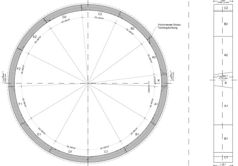
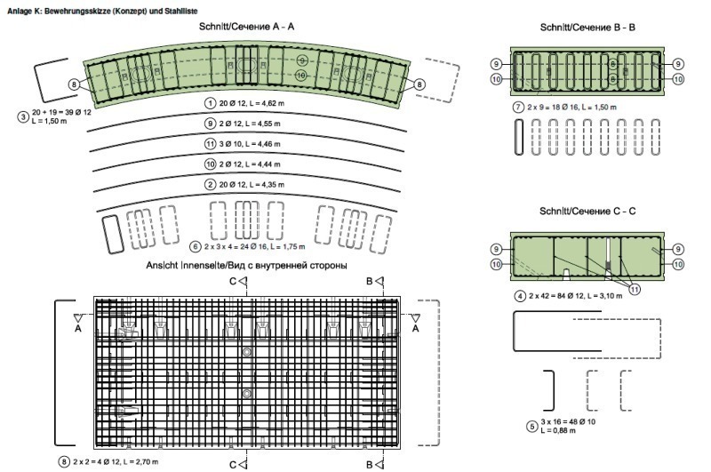
The Orlovski ring, with an external diameter of 18.65 m, a segment thickness of 70 cm and a ring width of 2.2 m, weights 215 t. As the maximum payload of a truck is limited to 18 t, a ring with 12 segments plus a small key was designed (Fig. 7).
For the segment design, only tapered ring should be used. Even for a nearly straight tunnel
Rmin horizontal = 5000 m,
Rmin vertical = 6000 m
the TBM is driving curves and the rings must follow the TBM drive. The tapered side should be on the tunnel back side of the ring (in direction of advance) (Fig. 8). It should be big enough to allow a ring erection back to the axis of the TBM tail. So, deformations of the new built ring when passing the tail sealing, will be avoided. If the key segment should al-ways be situated above tunnel spring line, left and right rings are favourable.
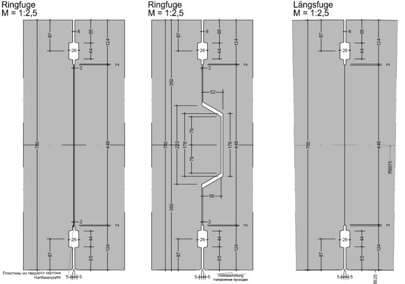
Flat circumferential/longitudinal joints are state of the art (Fig. 9). If connectors between rings and segments are used, they should be flexible and the coupling should not be assured by groove and tongue or pot and cam design. A pot and cam connection was chosen for safety reasons in the soft soils, with a sufficient clearance between both rings of 11 mm.
Coupling between 2 rings is possible by friction under the high longitudinal forces induced by advance pressure and must be calculated. The explicit wish of the client was, that a double sealing gasket inside and outside should be used. This is unusual, 1 sealing gasket near the extrados generally is enough.
For tolerance reasons, intermediate layers of hardboards are clued between the rings. On several international projects, intermediate layers were not installed and the contact in the circumferential joints was concrete to concrete. Operating experiences show, that the amount of cracks and broken parts of the segments did not increase if production accuracy and exact ring build was achieved.
6 Structural Analysis
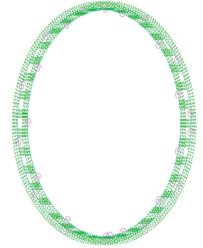
The segmental ring usually is calculated as a coupled double ring (Fig. 10). In a FEM program, only a single ring can be calculated, as coupling of 2 rings is not possible or very time consuming for most of all calculation programs.
To check extremes, a single ring with articulations and a single rigid ring is calculated, as well as rigid ring with a reduced area-wise moment according to Sir Allen Muir Wood‘s formula:
I reduced area-wise moment
= 0,01057 m4/m
Is area-wise moment of the force transmission zone
= 0,00739 m4/m
In area-wise moment of complete section
= 0,02858 m4/m
m number of segments (small key-segment not counted)
= 12
For the Orlovski ring, an area-wise moment reduction of 63 % was calculated with the Muir Wood formula. The calculated bending moments with this Muir Wood reduction only differ approx. 15 % from the moments, calculated with a more precise calculation for an articulated ring with moment springs in the longitudinal joints. In Fig. 11 the internal forces and deformations are shown for a typical load case.
Extensive effort is necessary, to verify the longitudinal and circumferential joints:
• Verification of partial loaded transverse areas
• Design of reinforcement for splitting forces
For segments, the allowed concrete stress in the partial loaded joints can be set to 3 times the allowed strength for dimensioning (Table 2).
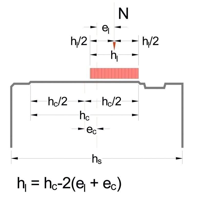
For the calculation, the loaded zone width is reduced by 2 times the eccentricity (e = eccentricity of contact zone ec + eccentrizity of load el) (Fig. 12):
hl = hc – 2 • (el + ec)
The eccentricity of load results from the internal forces:
Than the stress can be calculated with:
The splitting forces are calculated with the maximal normal force max Nd and the corresponding eccentricity e as well as for maximal eccentricity max e with corresponding normal force N.
FSd = 0,25 • Nd • (1 – hl/hs)
Then, the necessary reinforcement results from the formula:
aS = FSd/(fyk • γS) [cm²/m]
The splitting forces in circumferential direction, resulting from ram loads, generally are calculated with a FEM model (Fig. 5). At the end of all structural calculations and verifications, the dimensions of the segmental ring are finally defined and the reinforcement cage is designed (Fig. 13).
7 Steel Fibre Segments
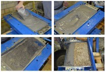
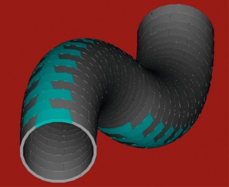
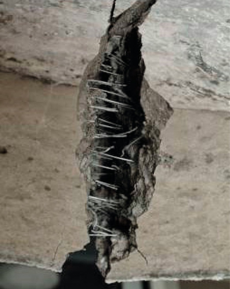
Concrete has a high compressive strength, but the tensile strength is low and must be disregarded in the verifications. By adding steel fibers, a new homogenous material with certain material properties is created. Fibers are not oriented within the concrete and take tensile strength in each direction (Fig. 14). The concrete gets a high ductility. Spalling and cracking during transport, ring erection and advance is reduced distinctly compared with segments with normal reinforcement.
Segments can be produced with steel fibers only, or with a combination „fibers and conventional steel bar reinforcement“. Steel fibers for segmental rings are 40 to 60 mm long with a diameter of approx. 1 mm and are bended up at the ends for anchoring. A minimal fiber content of 25 kg/m³ is necessary to reach an effect, 30 to 50 kg/m³ are used for most of all projects. For verification, generally tests are done, however all other structural analysis verifications must be done, too.
Segments with steel fiber reinforcement only are suitable for rings with lows bending moments and normal forces. High ram forces and partial loaded joints often demand additional bar reinforcement, which make the production more costly. To use steel fibres in addition or as only reinforcement, may be an option to reduce spalling and broken edges of the segments. Structural analysis for steel fibre reinforcement is not state of the art and needs a close cooperation with other consultants and independent checkers.
The use of steel fibre concrete for the Orlovski rings was examined but for the highly loaded big rings with high bending moments and normal forces, a high amount of bar reinforcement is necessary.
8 Resume
Segmental ring design for huge tunnels needs a tight cooperation between all involved experts. Soil parameters and loads must be determined in cooperation with the ground expert, the ring concept together with the TBM manufacturer and the logistic experts. And during the design phase, the concept must be adopted to new findings. As Sir Alan Muir Wood said in his book “Civil Engineering in Context”:
“The most essential element of design to be taught, therefore, is that it constitutes a system, conceptually represented as a series of iterative loops, the loops normally entailing communication between people or between people and computers.”
The Orlovski-Tunnel in St. Petersburg shows, that tunnel diameters, which were considered as „not possible for a TBM advance“ only a few years ago, now can be done. Therefore, aside of technical challenges for the machine construction, new dimensions of loads reacting on the segmental ring must be controlled and the feasability must be verified.