Optimisation of Constructional Fire Protection of a
Built-Over Underground Station Using Fire Simulation
 Credit/Quelle: Archilooks/sop Architekten
 Credit/Quelle: Vössing Ingenieurgesellschaft
![3 | Fire curves for rail vehicles with different lengths according to TRStrab [3]](https://www.tunnel-online.info/imgs/1/5/7/4/5/5/8/03-brandsimulation-u81-duesseldorf-trstrab-kurve-c7eeca8e9b9a9756.jpeg) Credit/Quelle: brandwerk traffic Ingenieurgesellschaft
Credit/Quelle: brandwerk traffic Ingenieurgesellschaft
 Credit/Quelle: brandwerk traffic Ingenieurgesellschaft
 Credit/Quelle: brandwerk traffic Ingenieurgesellschaft
 Credit/Quelle: Vössing Ingenieurgesellschaft
 Credit/Quelle: Vössing Ingenieurgesellschaft
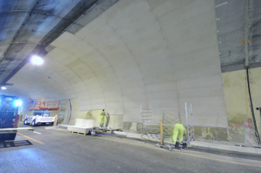
According to the German tram regulations BOStrab [1], constructional fire protection for underground transport structures in urban areas has to be paid particular attention. In addition to endangering passengers and emergency services in case of fire, the loss of structural stability can also endanger adjoining buildings. In order to ensure the structural safety of the new urban transit line U81 to Düsseldorf Airport – which will later be built over – even in case of fire, a detailed investigation of fire protection was already carried out in the design phase by means of a fire simulation. In the course of the investigation, constructional details were determined for the structural elements, which exceed the minimum requirements of the tunnel guideline [2] with a fire resistance class of F90-A and fulfil the required fire protection.
1 Introduction and Objective
At Düsseldorf airport, the future line U81 will run through an underground section with a running tunnel and the underground station “Flughafen-Terminal” (Fig. 1). Since the underground station may be built over later with loads on the individual columns, which are still unknown and were therefore specified on the safe side, and because of the light and open design of the station structure, including a flat ceiling with widely spaced columns and slender central columns, the fire safety design of the structural elements was already investigated in detail during the early design stage to verify the protection aim “structural safety in case of fire”.
The basis of the investigation using a fire simulation was the fact that possible fire loadings from vehicles are specific to types and therefore change in the course of time. Correspondingly a procedure was chosen, which considers the protection aim of structural safety independent of vehicle type. This way, a temperature-time curve could be obtained using a design fire and then used for the structural design.
In a multi-stage investigation process, first the constraints were specified for a fire simulation. As the decisive fire curve, full fire of a rail vehicle according to the TRStrab Brandschutz [3] (Technical rules for trams – fire protection) was chosen. From the fire simulation, the surface temperatures of the loadbearing elements were determined.
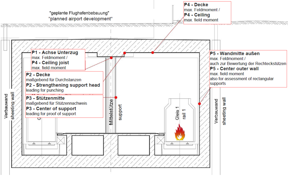
From the point of view of the structural engineer, the critical points are the fire loadings on the highly loaded central columns with the column heads, the middle of the slab and the external wall. For these elements, the temperature measurement points 1 to 5 were specified for the fire simulation model (Fig. 2).
2 Determination of Surface Temperatures
2.1 Model Formation
Simulation programs often offer the possibility of deviating from the requirements of the technical building rules and undertaking an individual verification based on the protection aims. Despite complex interfaces and insufficient technical specifications, the questions posed here can be answered technically correct and satisfactorily in economic terms. In this investigation, an engineering process was used to determine the temperature development at the surface of the decisive elements using a natural fire curve. The surface temperatures provide the basis for the subsequent thermal analysis and structural assessment.
For the investigation of the surface temperatures, the validated simulation program Fire Dynamics Simulator (FDS) was used.
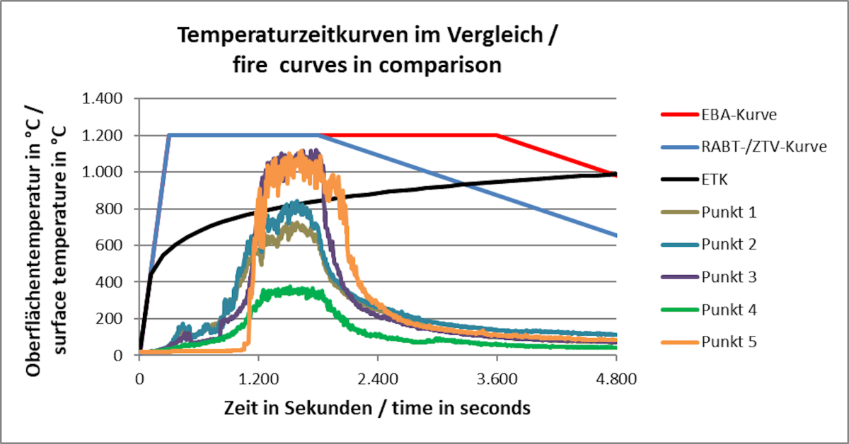
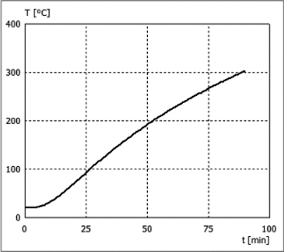
In the course of the preliminary considerations, a fire to a rail vehicle was decided as the decisive fire event and agreed with those involved with the design. The fire curve used was the conservative vehicle fire according to the technical rules for trams (TRStrab) for a 30 m long train. The fire curve can be seen in Fig. 3.
Furthermore, the specific material parameters of the individual components of the decisive travelling rail vehicle B80-C were implemented in the simulation model. In this way local temperature effects depending on the component could be represented and temperature- or material-dependent failure criteria could be stored.
2.2 Input Parameters of the Simulation
In the course of the preliminary investigations, general constraints were first decided. In addition to modelling of the structure, the train was represented realistically (including the materials and their specific parameters) in the cell grid of the calculation model. Particular attention was paid here to the failure times of the existing windows, since a significant part of the thermal energy escapes through the resulting window openings. In the course of the preliminary investigations, an approach on the safe side according to Kunkelmann [9] was followed, that assumes failure of the panes on reaching a threshold temperature. The result was that when the windows failed, flames came out of the vehicle and localised temperature peaks occurred to the tunnel walls in the immediate vicinity.
To ensure sufficient safety in the transfer of the calculation results to a simulation program, the adiabatic surface temperature was used to determine the thermal transport in the decisive elements. This value neglects thermal transport into the element and thus represents the thermal energy acting on the surface almost without losses. Therefore higher calculated temperatures are produced at the surface.
2.3 Results for Surface Temperatures
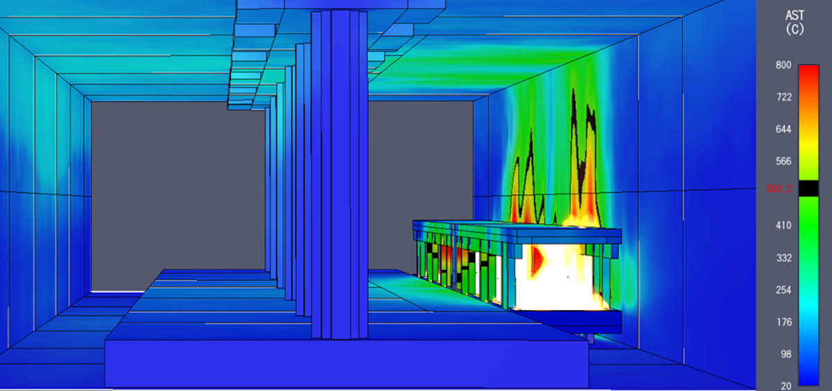
In the overall analysis for the determination of the element temperatures, numerous measurement locations were evaluated in the model. Fig. 4 shows an example evaluation time with illustration of the adiabatic surface temperatures in a tunnel section. It can be seen that several windows have already failed.
The scale shown at the right-hand side (20 °C to 800 °C) enables a visual analysis of the prevailing surface temperatures (with a surface temperature of about 500 °C shown in black). It shows that due to the failure of window panes, the highest temperatures of up to about 1100 °C are found at the wall surfaces in the immediate vicinity of the train.
A great difference could be determined between the surface temperatures at the columns in comparison with the roof slab elements. Direct comparison of the measurement equipment at the relevant columns shows that the vehicle construction and its element-dependent material properties have a significant effect on the occurring surface temperatures. For example, a temperature difference of up to about 25 % arose at the various columns along the train.
Due to the stated variance at the different measurement locations, the use of maximum values at the relevant elements is generally recommended so that local flow and temperature effects can be taken into account with adequate reliability. Fig. 5 shows the determined temperature-time curves for the station area (cf. Fig. 2) compared to curves from standards. From this it can be seen that the measured surface temperatures over the course of time exceed the ISO curve (DIN 4102-1;
Johannes Horvath [10]), also called Einheitstemperaturkurve ETK.
Therefore it could be verified that due to the assumed design fire, higher short-term temperatures (cf. Fig. 5, time period 1200–2000 seconds) occur than with the standard fire curve ETK. Related to the overall investigation period, however, the thermal loading is lower.
3 Element-Related Evaluation of the Simulation Results
3.1 Thermal Analysis of Construction Elements
For the thermal analysis according to DIN EN 1992-1-2 of the elements from Fig. 2, the transferred adiabatic temperature curves were prepared and the temperature development in the relevant elements was determined with the program Infocad and the additional module for structural analysis in case of fire.
Using the temperature curve with time, the evaluation procedure can be specified according to DIN EN 1992-1-2 [6]. For heating rates of between 2 K/min and 50 K/min, the material models for higher temperatures according to DIN EN 1992-1-2 can be used.
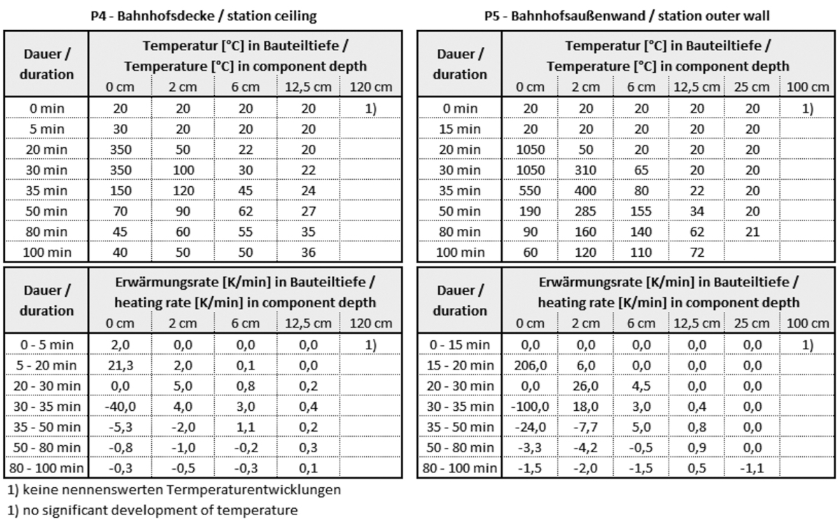
It shows that elements away from the fire location (central columns and roof slab) experience heating rates in the range according to standard, in contrast to the external wall immediately next to the train. The latter shows a very rapid temperature increase rate at the surface of max. 206 K/min (Fig. 6). However the heating rates are already in the range of the material models of DIN EN 1992-1-2 at a depth of 2 cm into the element.
The temperature profiles make clear that short-term high temperatures of the adiabatic curve are indeed reached at the surface of the elements. However the maximum temperatures 2 cm deep into the element only reach 400 °C and at 6 cm depth only a maximum of 155 °C, and thus lie clearly under the critical steel temperature of 300 °C according to ZTV-ING [8].
If the structural reinforcement is placed with 6 cm concrete cover in accordance with the ZTV-ING, a critical reduction of strength in case of fire is not to be expected in any element. This specification for the construction elements therefore fulfils the requirements of DIN EN 1992-1-2 (tabular process) and thus also the BOStrab tunnel guideline.
3.2 Comparison of the Results of the Fire Model With ETK-90
The assessment basis of constructional fire protection for elements according to the standard is the nominal standard temperature curve, which describes an artificial fire proceeding with digressively increasing energy liberation over time (Fig. 5). The resistance of construction elements against fire action is evaluated through the exposure time according to the ETK. So R90 represents the resistance of an element against the part of the ETK from 0 to 90 minutes (here ETK-90).
The thermal analysis of the ETK-90 fire curve gives considerably higher temperatures in the element than the fire curve determined for this project. The reinforcement at a depth of 6 cm would heat up to about 300 °C after 90 minutes (Fig. 7), which is clearly above the temperature from the fire simulation. The ETK-90 exposure therefore represents a considerably less favourable exposure for the element and lies on the safe side for usual tunnel structures according to BOStrab.
4 Conclusions for Structural Fire Protection
Based on the investigations that were carried out, the following constructional decisions could be made for the project:
The concrete cover in all loadbearing elements is specified not as given in DIN 4102-4 [7] but according to the ZTV-ING with 6 cm.
Application of surface reinforcement according to DIN EN 1992-1-2 or N-94 mesh or PP fibres according to the older or current ZTV-ING in the roof slab will be omitted since large-area spalling (maximum temperature about 200 °C at a depth of 4 cm in the element) due to slight construction moisture is improbable according to [6]. Furthermore, the investigated surface temperatures only describe locally occurring maximum values.
In order to take into account internal temperature-dependent stress constraints in the elements from the design case fire, the simplified verification according to ZTV-ING is suitable. This can be based on the actually exposed areas of the elements.
The performance of hot design in the course of the design for construction can also be omitted from the viewpoint of the preliminary investigation.
The additional investigations led to a reliable, reasonable design for constructional fire protection with the agreement of all involved parties. The constructional measures lead to an economic design with verified structural stability in case of fire.
In the revision of the tunnel guideline, it would be desirable to include indications under which usual constraints (e.g. the use of usual rolling stock concepts, no unusual fire exposure due to special use etc.) the minimum requirements for fire protection (F90-A) are sufficient for loadbearing elements. If there are special local conditions, e.g. buildings above the structure, the specification of a generally valid fire curve or a reference to the fire curves of the TRStrab Brandschutz for more detailed investigations using a fire simulation would be helpful.
Ehemals Vössing Ingenieurgesellschaft mbH, Teilprojektleiter „U81/1. Bauabschnitt (unterirdische Bauwerke)“, Düsseldorf, Deutschland
2 Formerly Vössing Ingenieurgesellschaft mbH, Head of Tunneling Department, Düsseldorf, Germany
Ehemals Vössing Ingenieurgesellschaft mbH, Abteilungsleiter Tunnelbau, Düsseldorf, Deutschland