Settlement Predictions for TBM Tunnelling in Soft Ground on the Basis of Empirical Values
 Quelle: HIC Holzhäuser Ingenieur Consult
 Quelle: HIC Holzhäuser Ingenieur Consult
 Quelle: HIC Holzhäuser Ingenieur Consult
 Quelle: HIC Holzhäuser Ingenieur Consult
 Quelle: HIC Holzhäuser Ingenieur Consult
 Quelle: HIC Holzhäuser Ingenieur Consult
 Quelle: HIC Holzhäuser Ingenieur Consult
 Quelle: HIC Holzhäuser Ingenieur Consult
 Quelle: HIC Holzhäuser Ingenieur Consult
 Quelle: HIC Holzhäuser Ingenieur Consult
 Quelle: HIC Holzhäuser Ingenieur Consult
 Quelle: Park et al. 2018
 Quelle: HIC Holzhäuser Ingenieur Consult
 Quelle: HIC Holzhäuser Ingenieur Consult
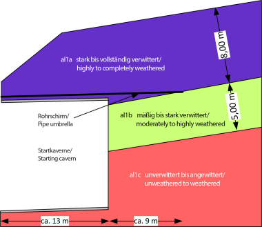
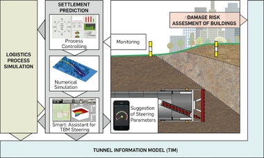
For the systematic analysis of a large number of settlement measurements of international tunnel projects with different project boundary conditions regarding TBM type, tunnel diameter, depth of the tunnel and subsoil conditions (Fig. 1), around 100 settlement troughs of completed projects are analysed in this paper, which were measured in the course of TBM tunnelling with a slurry or earth pressure balance shield in soft ground. The results of the systematic measured value analysis form the basis for calculation values and the proposed two-stage prediction model, the application of which – analogous to the observations of the field measurements – results in a range of settlement dimensions attributable to the respective excavation process.
1 Empirical Method for Determining
the Settlement Trough Caused by
Tunnelling
1.1 Geometry of Settlement Troughs
Determined by Measurements
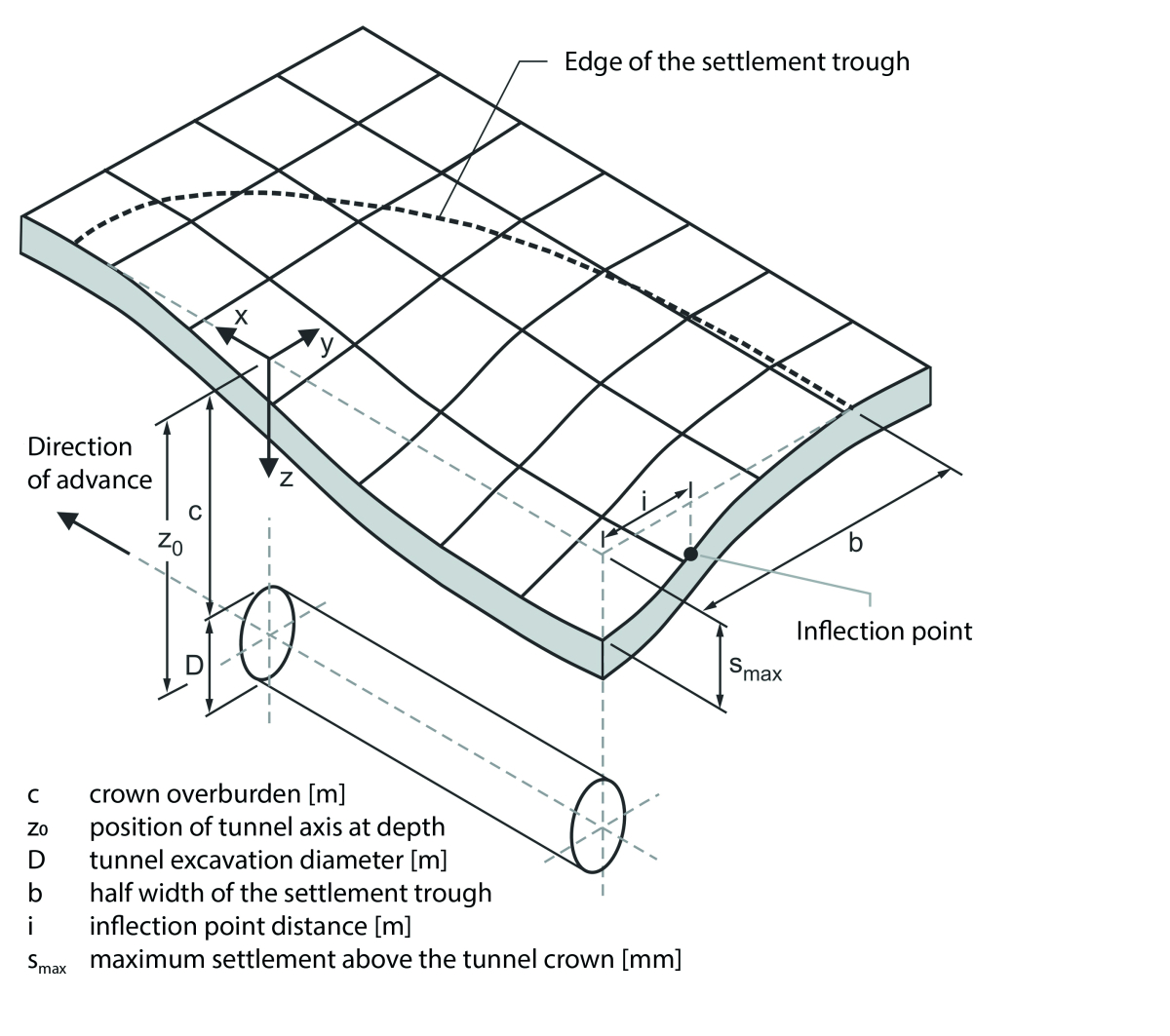
The empirical method, which was originally developed by Peck (1969) and whose application has since been further developed by numerous authors (O’Reilly & New 1982, Leca & New 2007, Fillibeck 2012, Mair 2013, Wang 2021), is widely used internationally and has been established for decades. The course of the transverse settlement trough of the tunnel is described by the Gaussian normal distribution. The settlement s(y) of the ground surface at a distance y from the tunnel axis can be described as follows:
s(y) = smax · e-y²/(2 · i²) (Eq. 1)
with smax denoting the maximum settlement above the tunnel crown, y the horizontal distance to the tunnel axis and i the inflection point distance, i.e. the distance of the inflection point of the settlement trough from the tunnel axis (Fig. 2).
The value i is largely dependent on the subsoil conditions and the depth of the tunnel. A widely used method for determining i was proposed by O’Reilly & New (1982):
i = K · z0 (Eq. 2)
with K being the dimensionless trough width parameter and z0 being the depth of the tunnel axis below the ground surface.
1.2 Volume Loss Approach
The volume of the settlement trough (i.e. the area of the settlement trough per meter of advance) is determined by integrating (Eq. 1):
Vs =
· i · smax (Eq. 3)
By referring to the excavation area of the tunnel cross-section At, the so-called volume loss (VL) can be determined from (Eq. 3):
VL = Vs / At (Eq. 4)
VL: Volume Loss [%]
Vs: Volume of the settlement trough [m²]
At: Excavated area of the tunnel cross-section [m²] with
At = π · D²/4 [m²]
D: Excavation diameter of the tunnel [m]
The volume loss is thus a measure of the size of the settlement trough, which is characterized by its width
w = 2 · b, the maximum settlement smax and the inflection point distance i.
2 Experience to Date Regarding Volume Loss (VL) and K Value Back-Calculated From Measured Values
In the UK in particular, empirical values for volume loss have been documented for decades on the basis of project examples. It has been shown that in stiff clays, such as the London Clay, volume loss values in the range of VL = 1 % to 2 % occur in drives with open shields (i.e. without face support) (Mair & Taylor 1997, Franza 2016).
For TBM drives with active face support, i.e. slurry shields and earth pressure balance shields, Mair & Taylor (1997) state that a high degree of settlement control can be achieved. This is particularly true in sands, where volume loss values of 0.5 % or less were frequently achieved.
In the following, the results of an in-house analysis of the empirical values for the volume loss and for the K-value (parameter of the settlement trough width) of TBM drives with active face support are summarized. Three selected project examples from the last 15 years, for which detailed settlement evaluations are available, are then explained in more detail.
2.1 Summary of Empirical Data for
Volume Loss
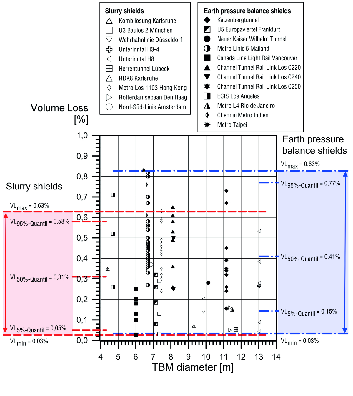
For the systematic analysis of a large number of settlement measurements from tunnel projects worldwide with different project boundary conditions with regard to TBM type, tunnel diameter, tunnel depth and ground conditions, around 100 settlement troughs from completed projects were evaluated in this report (Fig. 3), which were measured in the course of TBM excavations with a slurry or earth pressure balance shield in unconsolidated rock. Based on the measured maximum settlements above the tunnel and the shape of the settlement trough, the respective volume loss VL and the parameters of the settlement trough width K (see Section 2.2) were recalculated using the empirical method explained in Section 1.1. To close gaps in the measured values, the K value was estimated in 13 cases from previous experience.
Overall, this analysis shows a rather wide range of volume-loss values that occur almost regardless of the TBM diameter (Fig. 3). Singular extreme values, which sometimes occurred in particular where earth pressure
balance shields were used, were not taken into account in the analysis (Fig. 3).
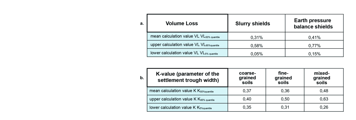
The back-calculated volume-loss values for drives with slurry shields ranged from VLmin = 0.03% to VLmax = 0.63% (VL5% quantile = 0.05%, VL50% quantile = 0.31%, VL95% quantile = 0.58%). A total of 32 settlement troughs were evaluated.
In comparison, volume-loss values of a similar scale were back-calculated in numerous cases for drives with earth pressure balance shields, although in some cases the values were slightly larger. The bandwidth ranged from VLmin = 0.03% to VLmax = 0.83% (VL5% quantile = 0.15%,
VL50% quantile = 0.41%, VL95% quantile = 0.77%). A total of 78 settlement troughs were evaluated.
The difference between the two bandwidths shown in Figure 3 can in many cases be explained primarily because the support of the face is more reliable with slurry shields than with earth pressure balance shields.
The corresponding maximum settlements measured for the drives with slurry shields ranged from 0.1 cm to a maximum of 3.6 cm (mean value 0.9 cm) and for earth pressure balance shields from 0.2 cm to a maximum of 2.8 cm (mean value 1.1 cm). Some of the tunnels driven with earth pressure shields had a greater crown overburden. These settlement dimensions are thus predominantly of a low magnitude and quantitatively prove that low-settlement tunnelling is possible with slurry shields and earth pressure balance shields.
2.2 Summary of Empirical Values for the
K Value (Parameter of the Settlement
Trough Width)
According to O’Reilly & New (1982), the following values for K can be used on the basis of field measurements:
K = 0.5 for cohesive soils (0.4 for stiff clays and 0.7 for soft, silty clays)
K = 0.25 for granular soils (range: 0.2 to 0.3)
Mair & Taylor (1997) have analysed a large number of completed tunnel drives – most of these were drives with single shields (open shields without active face support). For tunnels in clays, the approach of K = 0.5 already proposed by O’Reilly & New (1982) is confirmed by the majority of the cases analysed, irrespective of the consistency of the cohesive soil in each case. The data are predominantly within a range of K = 0.4 to K = 0.6.
For tunnels in sands and gravels, Mair & Taylor (1997) found a slightly larger scatter compared to clays: Predominantly, the analysed data lie within the range of K = 0.25 and K = 0.45 (mean value: K = 0.35).
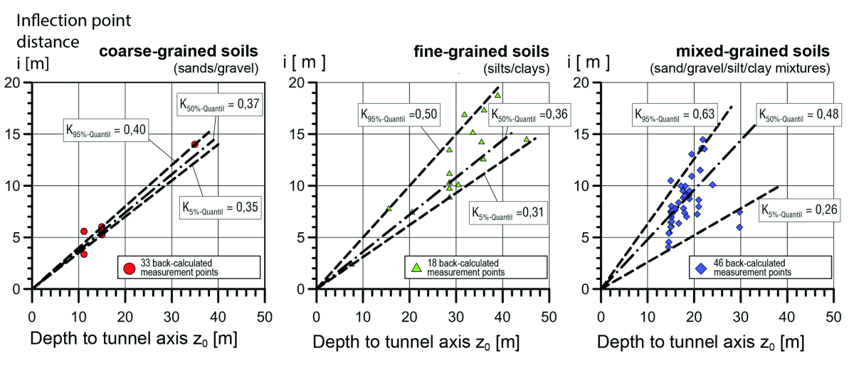
The results of the evaluation of around 100 settlement troughs carried out for this report, which were measured in the course of the execution of TBM projects with a slurry or earth pressure balance shield (Fig. 4), largely confirm the range of the above-mentioned empirical values. However, they also show the variability of the K value that occurred in each case, which results from the back calculation of the settlement troughs measured in situ during TBM drives.
This variability should be taken into account in settlement forecasts for planned tunnel projects. In Figure 4, a distinction was made between coarse-grained, fine-grained and mixed-grained soils. After statistical
analysis, the values for the 5%, 50% and 95% quantiles are given in each case. The dispersion of the K values determined on the basis of the measured values is lowest in coarse-grained soils and highest in mixed-grained soils.
2.3 Project Example 1:
Milan, Metro Line 5
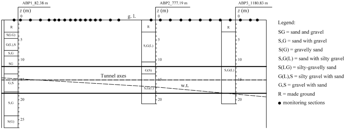
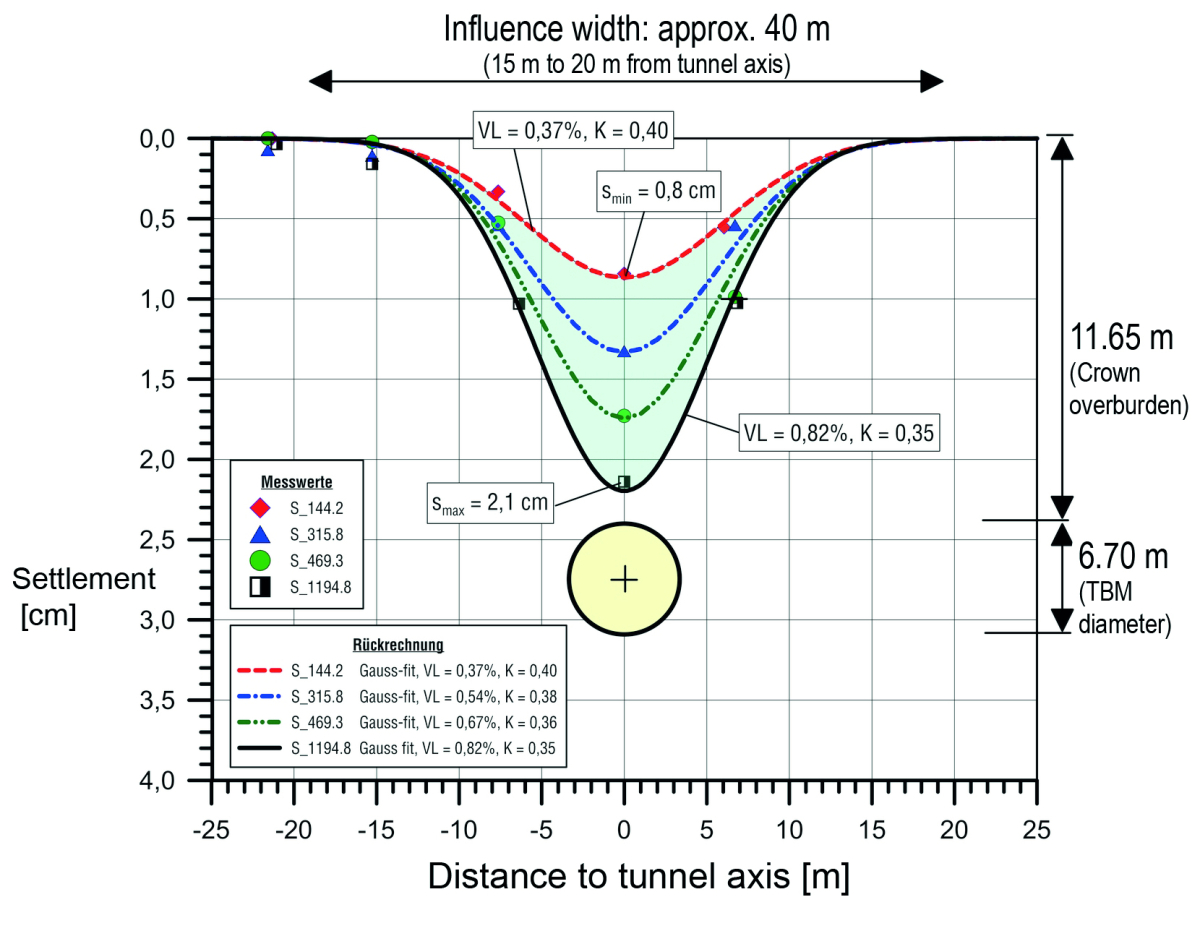
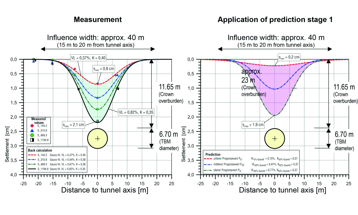
A well-documented project example is the construction of Metro Line 5 in Milan (Fargnoli et al. 2013). Here, two tunnel bores were excavated over a tunnel length of 12.6 km using an EPB TBM (Ø 6.70 m) (horizontal axial spacing 15 m). Between the San Siro Harar and Segesta stations, a 1.3 km section of the tunnel passed under a measurement field. The ground consisted of medium-dense to densely bedded sands and gravels, some of which were silty (Fig. 5). The groundwater table was predominantly located within the level of the tunnel face. The overburden over the tunnel crown measured approx. 11.65 m – this corresponds to 1.74 times the tunnel diameter.
Figure 6 shows a partial representation of the settlement values measured in situ after excavation by the first TBM on the basis of four measurement cross-sections, resulting in a range of 8.4 mm to 21.4 mm. A total of 29 measurement cross-sections were traversed. The measured settlements for all measurement cross-sections were between 6.0 mm and 21.4 mm in total (mean value: 12.4 mm). Thus, settlements were determined ranging from a minimum of 48 % to a maximum of 172 % of the mean value, demonstrating the wide range of settlement values that occurred in situ with an almost constant cover and similar ground conditions.
In this case, the volume loss back-calculated from all settlement measurements ranged from 0.27 % to 0.82 % (mean value: 0.5 %). The corresponding back-calculated K value, which is decisive for the width of the settlement trough, was within a comparatively narrow range of 0.35 to 0.40 (mean value: 0.38) for the predominantly coarse-grained soils present here (see also Figure 4).
2.4 Project Example 2:
Hong Kong Metro (Lot 1103)
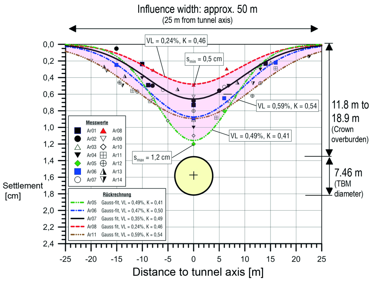
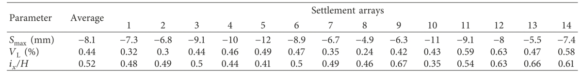
During the construction of the metro in Hong Kong (Lot 1103) with a slurry shield (Ø 7.46 m) in alluvium (gravelly, silty sands) or completely unconsolidated granite with loose rock properties, an approximately 230 m long measurement field was tunnelled in a green area with an overburden above the tunnel crown of approx. 11.8 m to 18.9 m during the excavation of the first bore (down-track tunnel) (Park et al. 2018). The settlements of the ground surface were recorded in a total of 14
measurement cross-sections (Ar01 to Ar14). Settlements of 4.9 mm to 12 mm (mean value: 8.1 mm) occurred above the crown (see Figure 7 and Table 1). Here, volume loss ratios of 0.24 % to 0.63 % (mean value: 0.44 %) were recalculated. The corresponding K values (mixed-grain soils) ranged from 0.35 to 0.67 (mean value: 0.52).
2.5 Project Example 3:
Katzenberg Tunnel
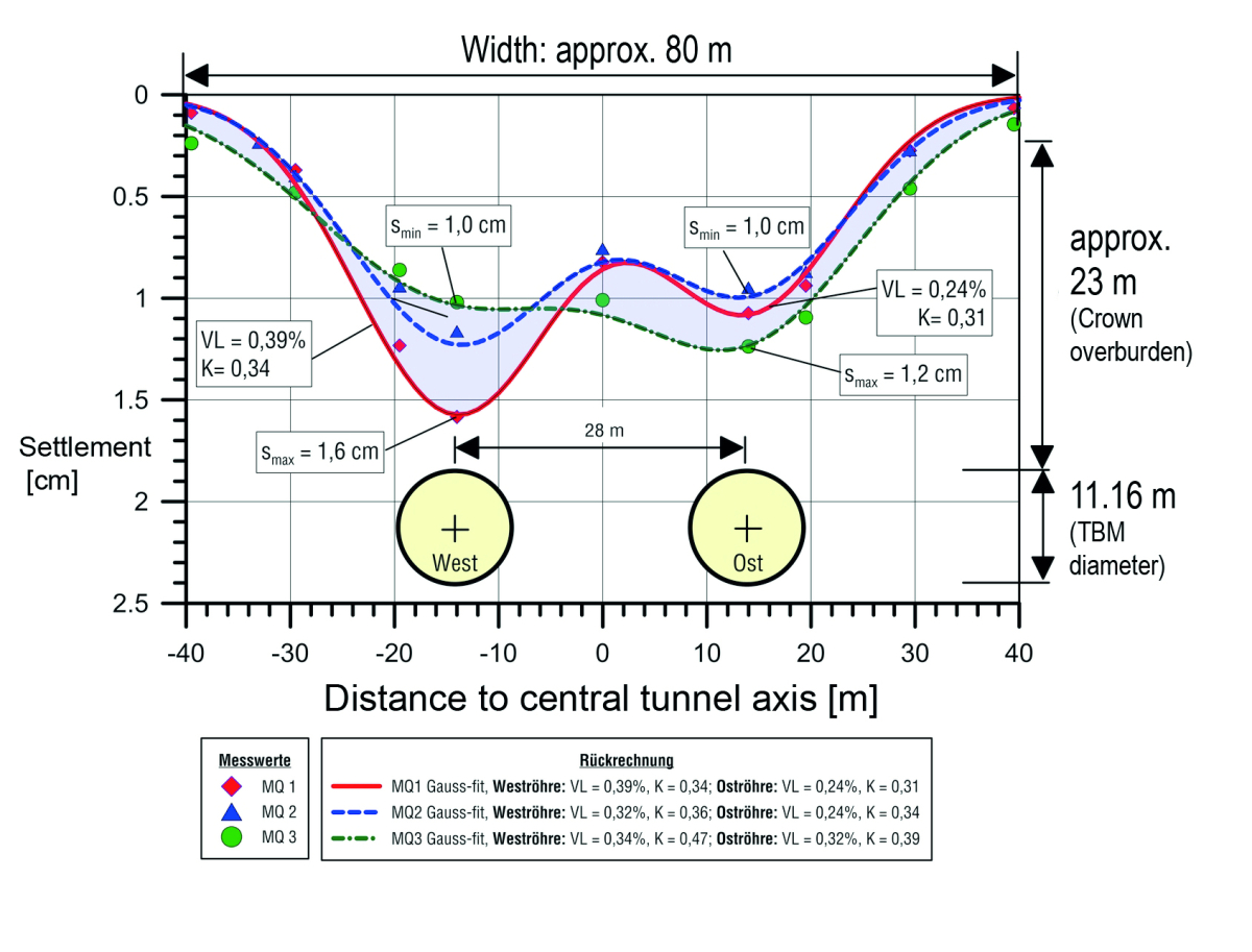
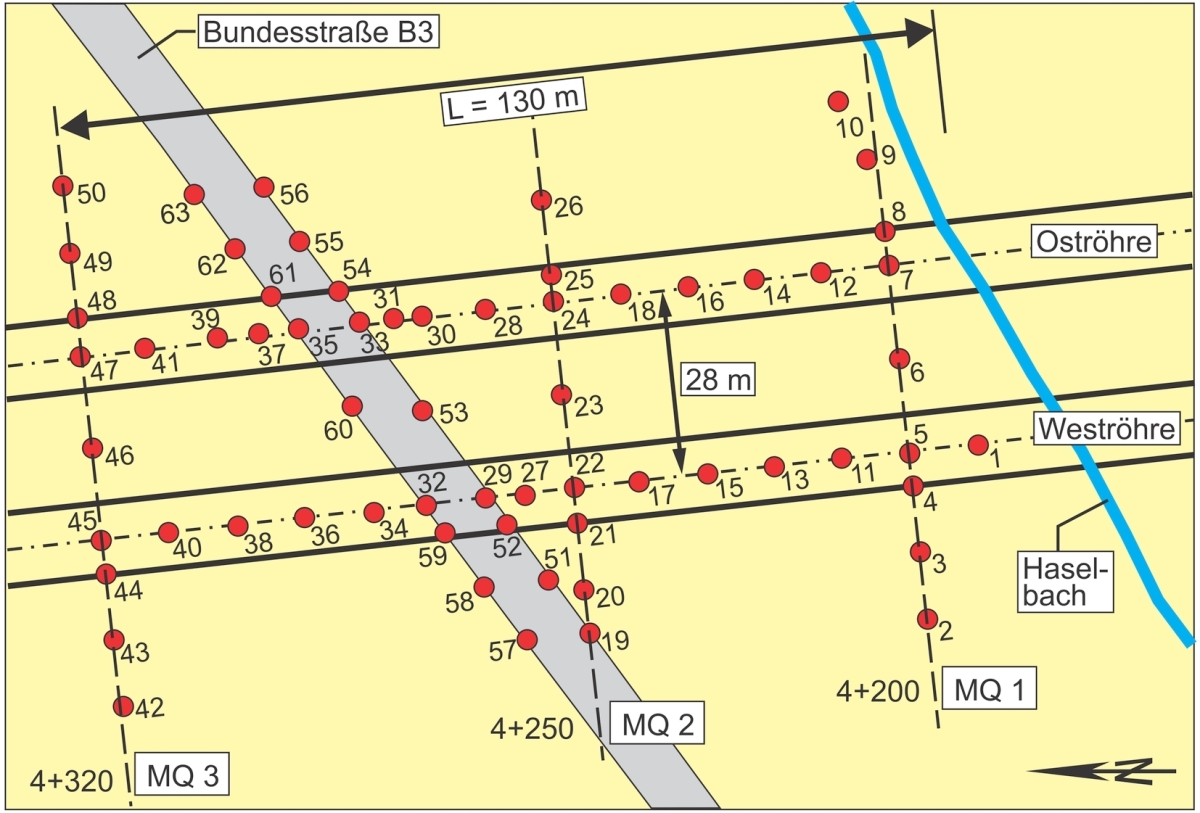
Two tunnel boring machines (TBMs) with a bore diameter of 11.16 m were used to excavate the approximately 9 km long Katzenberg Tunnel (Kirschke & Holzhäuser 2008). In preparation, an extensive measurement field was traversed (see Figures 8 + 9). In two longitudinal and three transverse profiles with a total of 63 measuring points, the settlements of the ground surface were measured before, during and after the driving (Fig. 9). The two EPB-TBMs were operated here in closed mode (i.e. with active face support), with foam being used as the conditioning agent. The overburden of the crown here was approx. 23 m, the horizontal axial spacing of the two tunnel tubes 28 m. Below the approx. 4 m thick loess/loess loam, the fine-grained subsoil consists mostly of weathered to deconsolidated claystone down to the tunnel.
Figure 8 shows the settlements measured in the three transverse profiles after the passage of both TBMs. Maximum settlements of 16 mm occurred above the west tube. The settlement troughs are around 80 m wide in total and exhibit the W-shaped course typical of twin-tube tunnels with maximum values above the tunnel axes and slightly lower settlements between the two tunnel tubes. The measured values also show that the effects of tunnel driving on the ground surface are subject to considerable scatter. It is also evident that the settlement troughs are not always symmetrical to the central axis of the tunnel (Fig. 8). In the three measurement cross-sections in the transverse direction of the tunnel, the maximum settlements measured above the west tunnel range from around 10 mm to 16 mm. If all measuring points located above the west tube in the longitudinal section are included, the range of the total measured settlements increases to 8 mm to 18 mm (mean value: 14 mm). In relation to this mean value, the settlements that actually occurred above the west tube reached values of a minimum of 57 % and a maximum of 129 %, i.e. the settlements amounted to a minimum of around half and a maximum of 1.3 times the mean value.
The back-calculated volume loss was in the range of 0.24 % to 0.39 %, and the parameter K was determined in a range of 0.31 to 0.47. The settlement trough in the transverse direction back-calculated for MQ1 (measurement cross-section 1) from the settlement measurements has a maximum local tangent slope of around 1:1000.
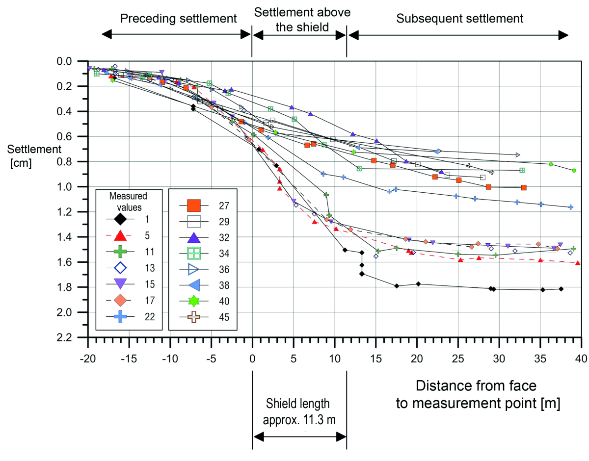
On average, the preceding settlements above the west tube amounted to 5 mm (this corresponds to 36 % of the mean total settlement of 14 mm), 6 mm settlement (43 %) occurred above the shield, and 3 mm (21 %) were subsequent settlements. The average longitudinal slope is therefore 1:1900 over the shield with a settlement proportion of 6 mm and a shield length of 11.3 m. At its maximum, this settlement proportion was 8.5 mm (Fig. 10), resulting in a maximum longitudinal slope of around 1:1300.
This means that at the Katzenberg tunnel in the “B3 undercrossing” measurment field, the largest inclination of the settlement trough occurred in the transverse direction (maximum: 1:1000), which was around 30 % greater than the temporary inclination in the longitudinal direction (maximum: 1:1300).
3 Recommended Procedure for
Settlement Predictions for Planned TBM Drives in Unconsolidated Rock
3.1 Calculated Values for Volume Loss and
K-Value (Parameters of the Settlement Trough Width)
The measured values from completed TBM projects shown in Section 2 illustrate that settlement values and settlement troughs always occur within certain bandwidths, which should therefore also be considered in settlement forecasts.
The analysis of around 100 settlement depressions
described in Section 2.1 is summarized in relation to the back-calculated volume loss (VL) in accordance with
Table 2a. A distinction is made here between slurry shields and earth pressure balance shields. The volume loss is characterized by a lower, middle and upper calculated value VL (see also Figure 3).
Similarly, Table 2b summarizes the analysis results of the K-values (parameters of the settlement trough width) from Section 2.2. A distinction is made here between coarse-grained, fine-grained and mixed-grained soils, which are present between the tunnel and the ground surface in the examined projects. The K-value is also characterized by a lower, middle and upper calculation value K (see also Fig. 4).
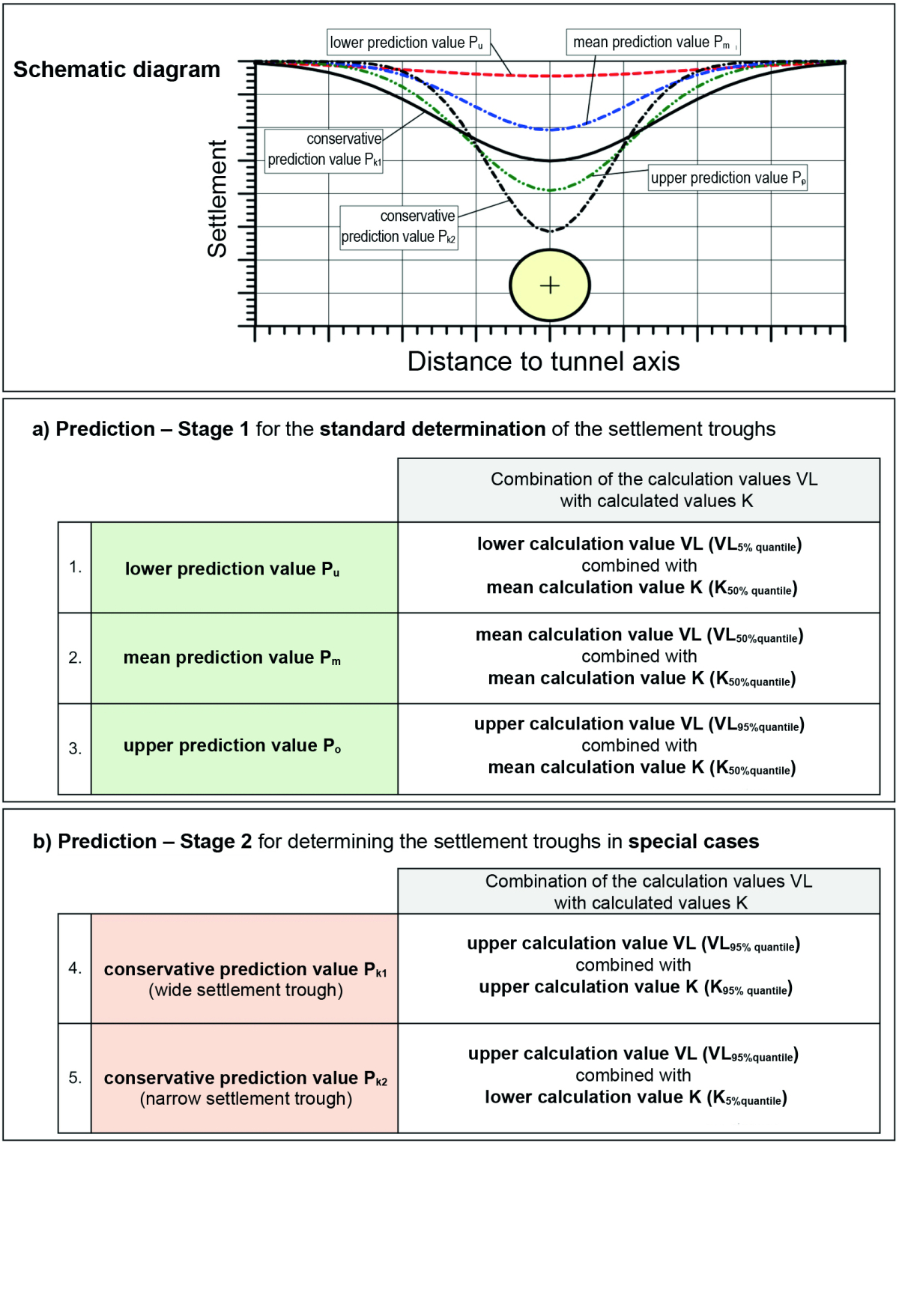
3.2 Prediction Stages 1 and 2
In the next step, the calculation values VL (volume loss) and K (parameters of the settlement trough width) (see Section 3.1) are correlated with each other in selected combinations, resulting in dedicated prediction values and prediction bandwidths for practically relevant boundary conditions in the context of the settlement prediction. In prediction level 1, the standard application of which is recommended, a distinction is made between the lower, middle and upper predicted values Pu , Pm and Po (Table 3a).
Prediction Stage 1
The analysis of the measured values of reference projects (see Sections 2.1 and 2.2) has shown that the variation range of the Volume-Loss value is considerably greater than that of the K value. The volume loss value is therefore varied for prediction stage 1, i.e. the 5 %, 50 % and 95 % quantiles for the volume loss are used in accordance with Table 2a and Figure 3, while the 50 % quantile of the K value is used uniformly for the K value approach in accordance with Table 2b and Figure 4.
Prediction Stage 2
Depending on the requirements of the project, prediction stage 2 may be necessary, e.g. as an extreme value analysis. The analysis of the reference projects in Section 2 has shown that not only the volume loss but also the K-value
is subject to a certain degree of scatter – especially in the case of fine-grained and mixed-grained soils. Furthermore, this influences the width of the settlement trough and the local inclination of the settlement trough as a measure of the inclination of the ground surface caused by tunnel excavation. It may therefore be necessary to analyse both wider and narrower settlement troughs compared to prediction stage 1.
A distinction is made between the conservative prediction value Pk1 for estimating a wider settlement trough when considering the ground surface (or structures) at a greater distance from the tunnel alignment and the conservative prediction value Pk2 for estimating a narrower settlement trough when considering the ground surface (or structures) in the immediate vicinity of the tunnel alignment (see Table 3b).
In both cases, the upper calculation value VL (volume loss) is applied. This is combined with the upper calculation value K for the wide settlement trough and with the lower calculation value K for the narrow settlement trough. Within prediction stage 2, boundary values from the statistical evaluation for the K value and the volume loss are also taken into account. It should be noted here that the settlement troughs of structures can deviate from the greenfield settlements discussed in Sections 1.1 and 2.2 owing to the structural stiffness.
The application of prediction stage 1 when using the equations listed in Sections 1.1 and 1.2 is explained below using the EPB drive for Metro Line 5 in Milan as an example (for the corresponding measured settlement values, see Section 2.3). Depending on the tunnelling method, the calculated values VL from Table 2a for earth pressure balance shields and the calculated values K for coarse-grained soils from Table 2b were used in accordance with the ground conditions encountered at the example project in Milan and then combined in the same way as in Table 3a for prediction stage 1. The range of settlements estimated when using prediction stage 1 (red area in Fig. 11, right) realistically reflects the range actually measured in the measurement cross-sections selected as examples (green area in Fig. 11, left).
The range of maximum settlements from the calculated settlement troughs for the lower, middle and upper prediction values shows the corresponding variation of the applied calculation value VL for the volume loss (see Figure 11 right). On the other hand, the variation of the calculation value K (parameter of the settlement trough width) affects both the width of the settlement trough and the maximum settlement, which are determined, for example, in prediction stage 2 with the conservative prediction values. The scatter of the calculated value K for the coarse-grained soil in the project example in Milan is relatively low compared to the two other options of fine-grained and mixed-grained soils considered (see Figure 4 and Table 2b).
4 Summary and Outlook
This article statistically evaluates around 100 measured settlement troughs that were documented during the construction of TBM drives in unconsolidated rock using slurry or earth pressure support. The aim is the compilation and systematic analysis of these empirical values as well as the development of a recommendation for the preparation of settlement predictions on the basis of measured values obtained in situ. The application of these predictions results in a range of expected settlement values caused by tunnel driving - analogous to the observations of the field measurements.
In addition to the tunnel diameter and the depth of the tunnel, the volume loss and the K-value (parameter
of the settlement trough width) are the key parameters for the analytical description of settlement troughs as a result of tunnel driving.
Volume loss (taking into account the tunnelling
method) and K-value (taking into account the existing ground) were back-calculated and statistically evaluated from the measured settlement values of around 100 settlement troughs in the sample projects. The 5%, 50% and 95% quantiles were determined for both parameters and listed as the lower, middle and upper calculated values VL and K respectively.
For the sake of clarity and simplicity, the corresponding calculated values were differentiated for the volume loss according to the type of excavation (slurry and earth pressure balance shields) and for the K-value
separately for coarse-grained, fine-grained and mixed-grained soils. Both the volume loss and the K-value in situ do not depend exclusively on the parameters according to which they are differentiated in this report. It can be assumed that they are subject to a complex interplay of diverse influences.
Overall, the analysis shows a fairly wide range of volume loss values back-calculated from excavations with a slurry shield or earth pressure balance shield in unconsolidated rock. This range is found to be almost independent of the TBM diameter.
In prediction stage 1, the possible settlement depressions are determined as standard with the lower, middle and upper prediction values Pu, Pm and Po. For this, the mean calculation value K (50 % quantile of the parameter of the settlement trough width) is combined with the lower, mean and upper calculation value VL (5 %, 50 % and 95 % quantiles of the volume loss). As a result, there is always a certain range for the predicted settlements in accordance with the measured values of the reference projects.
In prediction stage 2, two further combinations, the conservative prediction values Pk1 and Pk2, are used for extreme value analysis. This can be used depending on the specific task, e.g. when investigating structures in the immediate or wider vicinity of the tunnel route. Here - analogous to the scattering of the K-value determined in situ - wider and narrower settlement troughs are examined than in prediction stage 1. This means that within prediction stage 2, marginal values from the statistical evaluation for the K-value and the volume loss are also taken into account. Due to the structural stiffness, the settlement troughs of structures can deviate from the greenfield settlements discussed in Sections 1.1 and 2.2 with a generally shallower trough.
The settlement estimation with the help of prediction stages 1 and 2 shows a range of maximum settlement dimensions and settlement trough shapes that can result from the evaluation of around 100 settlement troughs from project examples.
If these prediction stages 1 and 2 are applied to the evaluated projects, in some cases there is very good correspondence between the calculation and the measured settlement values (see e.g. Metro Line 5 in Milan). However, there are also example projects in which this forecast significantly overestimates the measured values that occurred in situ.
For tunnel projects currently in the planning stage, the computational settlement estimate should not be based on overly optimistic boundary conditions but should generally be conservative.
To date, there is no calculation method with which a precise prediction of the excavation-related settlement dimensions and the shape of the settlement troughs can be made for any common project boundary conditions, confirmed by measured values and providing a reliable justification for the sometimes very different deformations observed in situ.
In individual cases, a recalculation of settlement measurements, e.g. using the finite element method, has been successful and the influence of individual parameters could be clearly analysed (Leca & New 2007, Mair 2013). However, a reliable comprehensive transfer of such numerical models to other project boundary conditions is not yet possible - presumably due to the heterogeneity of the influencing factors, such as the ground properties, the process technology during TBM operation and the various interactions that occur.
It is therefore all the more important to examine empirical data to determine which settlement behaviour has already occurred in other comparable projects and, based on this, which settlement behaviour can presumably be expected in newly planned projects (prediction stage 1) or which maximum settlements/settlement differences/displacements cannot be ruled out (prediction stage 2). Prediction stages 1 and 2 are to be categorized in this context.