Mechanised Driving in Subsoil prone to Clogging, Part 2
In the first part of the report (tunnel 1/2009, pp. 25) it was shown that the clogging process does not solely depend on the composition of the subsoil but also to a high degree on the
nature of the excavation process. As a result for a successful drive it is essential to ensure that optimal harmony is attained between the subsoil and the process technology. The choice of driving technology is thus of absolute importance.
Selecting the Driving Technology
Optimal harmony between the subsoil and the process technology is essential for a successful excavation. In this connection the driving technology must adapt to the subsoil, as this is prescribed in conjunction with its properties, which at the most can only be altered to a certain extent involving considerable outlay. The investigating, evaluation and interpretation of the subsoil in advance of a tunnelling scheme are thus of central importance.
Frequently contractual marginal conditions on the type of drive are provided in addition to the results of the explorations that were undertaken. These conditions are often couched in such restrictive terms that a bidder, who would prefer another method, renounces putting forward an alternative concept if only to assure equality in bidding and to avoid additional risks.
Furthermore a bidder can only take advantage of his experience and expertise when selecting the driving concept providing that proper information is made available to him regarding both quantity and quality together with the tendering documents [8]. General indications that subsoil prone to clogging might be encountered do not really help. In particular details on the expected incidence of water have to be precise and sustainable, as they substantially influence clogging processes.
There are no recurring standard solutions for the choice of machine concept. Instead technical solutions that are especially tailored to the tunnelling project are required – from the cutting wheel design right up to the removal and depositing of the material [9]. This also applies particularly to the issue of clogging. Admittedly mechanised driving in the interim provides a whole range of technical possibilities, by means of which subsoil prone to clogging can be excavated, but in contrast to other factors of influence frequently new ground is encountered when assessing problems connected with clogging. This is because first and foremost the clogging potential can only be insufficiently assessed on the basis of conventional lab tests and special tests, which provide direct indications of the optimal driving technology, have so far not been properly evolved [10].
Generally it is essential to increase the subsoil clogging potential as minimally as possible through the driving method and to ensure that the excavated material remains more or less unaltered in the subsoil regarding its consistency.
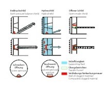
This requirement indicates that an efficient full-excavation without supporting the face and with conveyor belt extraction at the centre of the cross-section should be attempted. In the case of this method the excavated material is gathered with little expenditure of energy after the extraction process by means of a cutting wheel bucket elevator and dropped on to the conveyor belt. The prerequisites for this type of excavation are, however, a stable face and dry conditions, otherwise clogging can occur in the cutting wheel bucket elevator as well as at the transfer point on the conveyor belt, which can no longer be mastered (Fig. 8).
In contrast to this in the case of machines with a suspension circuit for conveying the excavated material, also known as hydro drives, the face is automatically supported thanks to the liquid pressure. This can be very accurately controlled and regulated by pressure control thanks to an air cushion. Hydro drives are preferably used in the consistency range from pasty to liquid, which is not particularly prone to clogging. Ingressing water is repelled by the suspension under pressure. However, the method only caters for a narrow spectrum regarding the suspension density in the feed and delivery lines on account of the suspension pumps that are applied. In addition the preparation of suspension and separation of soil are extremely complicated and thus result in restricted performance in the case of soils with a high proportion of fines, especially if considerable portions of them disperse. Furthermore in the case of hydro drives there is the problem that uncontrolled discharges of suspension can take place into the surrounding subsoil. Should too little movement prevail in the flow of suspension then non-dispersed particles of clay can precipitate in niches, pockets etc. and lead to clogging in and around the cutting wheel, the extraction chamber as well as at the rock crusher, rake and suction pipe. “Cleans-ing” only takes place providing that there is a sufficient quantity of gravel and sand present in the mixture so that clogging phenomena remain confined. Methods involving a suspension circuit are thus especially suited for subsoil with only limited clogging potential and sufficient volumetric proportions of gravels and sands.
Driving technology with worm discharge on the other hand can operate in an extremely wide consistency range, extending from solid to pasty and also covering the entire fine-grain granulation scale. In addition the filling level of the extraction chamber can be varied so that the given requirements for face supporting can be adapted to. As the filling level increases the consistency of the excavated material in the extraction chamber has to be altered so that it is basically pasty in order to restrict the torque. This signifies that the excavated material has also to be plastifiable through adding water and if need be a conditioning agent and/or artificial soil. Towards this end the grain distribution of the excavated material plays an important part – whereas only the effectively available grain size distribution in the material or slurry is determining [11].
Should plastification be possible, on the other hand an increase in the inclination to clog must be reckoned with should the subsoil possess a solid consistency and be altered in its consistency by the drive to adopt a liquid state, as the danger of clogging is especially great in the consistency range of soft to stiff lying in between.
Subsequently the various operating modes for an EPB machine with pressure-reducing worm discharge and the possibility to work using the earth slurry method are explained. Such machines are characterised by
– mastering a wide range of configurations for the excavation,
– the possibility of undertaking a drive without support, with compressed air or slurry supporting of the face
– and to enable the necessary conversion from a partly to a completely filled extraction chamber to take place in the short term.
Generally speaking as the extraction is filled, on the one hand the necessary energy input, the quantity of required conditioning agent and the tool wear increase and on the other the rate of advance drops. As a result an effort is made to execute the drive as far as possible employing a partly filled extraction chamber.
Driving with a partly filled Extraction Chamber
An effort should be made to apply a driving method with which the excavated material is altered as little as possible given subsoil prone to clogging. For particularly in the case of intermittent beds with large-grained water-bearing layers it is essential to exploit the fact that generally speaking layers prone to clogging possess lower water contents and can be conveyed without clogging phenomena while keeping water away. This can best be achieved by means of an EPB drive with only a partly filled extraction chamber. In addition driving with a partly filled extraction chamber allows the face and the excavation tools to be inspected at short notice without any complication.
Given low amounts of ingressing underground water, the amount of underground water entering is so slight compared to the quantity of excavated material that clogging can only occur during phases of standstill. For a successful drive under such conditions it is necessary to remove the water that has collected during the standstill phase in the extraction chamber as soon as possible or to bind it in such a manner that it cannot moisten the exposed surfaces in the extraction chamber.
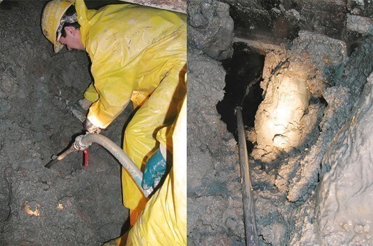
Although it is possible to remove water via the worm, this not usually applied because the water can lead to problems on the follow-up transport, disposal and water preparation systems or cannot be mastered. On the other hand binding the water with excavated material functions extremely well because the amount of water is small compared to the proportion of excavated material, as free water can be removed from the dry excavated material without much trouble. Lumps of moist material form, which are enveloped by a layer of dust-dry material (Fig. 9).
Should there be considerable water in the extraction chamber in proportion to the excavated material as can occur following a lengthy standstill or given increased amounts of ingressing underground water, the water can no longer be completely bound by the water that is present. In order to be able to transport the water from the extraction chamber, first of all an attempt is made to homogenise the excavated material. Towards this end slurry with a pasty to soft consistency is produced, which must have such a capacity to flow that it moves through the rotations of the cutting wheel towards the worm and from there can be carried away out of the extraction chamber. Should the excavated material be too liquid the mentioned problems on the follow-up installations result, however, if it is too stiff, it sticks to the cutterhead and the pressure wall. In order to remove such clogging, additional water must then be added to the extraction chamber. Only after the bulk of the excavated material has been removed from the extraction chamber, the addition of water is ceased and the drive resumed.
The time-consistency diagram in Fig. 10 shows how the excavated material can be brought through the critical consistency area after a lengthy standstill phase given an average amount of ingressing water (red arrows). The green arrows indicate on the other hand how the consistency of the excavated material would change if no water was added.
The difference between the red and the green arrows relates to the speed with which the areas with consistency, which are critical regarding sticking, are passed through. The simultaneous cessation of the addition of water and the resumption of the drive linked with the addition of dry excavated material leads to a rapid increase in the consistency of the excavated material. This is of importance in as much as this material can lead to caking in the extraction chamber and the worm. In the process the caked material produces constrictions in the flow rate, something that leads to high pressures, an increase in the drive torques, increased current consumption and in turn higher temperatures and subsequently to greater wear of the mechanical parts. In an extreme case on account of the caking it can e.g. lead to bridging in the extraction chamber and also to plugging in the worm.
Under such conditions temperatures of up to 200° C can be attained in the worm. Often the required drive torque increases to such an extent that the worm’s rpm drops to zero and the worm is blocked. If water is added in time to the worm in such situations so that the surface is lubricated, the required torque drops and the worm’s rpm subsequently increases again.
After a standstill in delivery the worm starts up with the conditions prevailing prior to the standstill. Subsequently the “new consistency” begins to act with altered filling of the worm. After a certain time the excavated material with an increased proportion of water from the standstill phase is removed and the drive returns to the “normal situation” as can be clearly seen in Fig. 11 in the development of the worm torque following a standstill.
In the case of pronounced amounts of ingressing water it is no longer possible to attain any solid material consistency with the newly extracted material. Conditioning must then be geared to ensuring that the excavated material maintains a pasty consistency. However, a 2-phase mix can evolve especially when the amount of ingressing water is high, as above all, liquid and soft to stiff excavated material is not at all easy to homogenise. Generally speaking the soft to stiff excavated material sticks to all parts, which are not subjected to mechanical stress, whereas the material in the liquid phase collects in the cavities, which are kept exposed by the rotor, stator and worm. As the clogging excavated material on the rear wall of the cutting wheel can extend far into the extraction chamber forming an even and smooth surface, rotating the cutting wheel only results in insufficient mixing. Such cases of clogging can only be removed if it is possible to apply conditioning agents in the cutting wheel from the front. A problem in conjunction with a TBM drive in intermittent beds with water-bearing layers prone to clogging is first and foremost the factor that difficulties with clogging lead to a reduced rate of advance and an increased number of standstills as a result of which an increasingly unfavourable ratio of water to dry mass results in the excavated material. As consequently clogging problems further increase the rate of advance drops still further resulting in a vicious circle. This can only be prevented providing that the crew possesses experience in dealing with clogging and is familiar with process technology designed to cope with it.
Drive with full Extraction Chamber In the event of high amounts of ingressing underground water or unstable face conditions 2 possibilities are available:
– filling the extraction chamber with an increased amount of excavated material,
– admitting compressed air to the extraction chamber.
Should these possibilities not suffice or if full-face supporting of the face with slurry is required then the drive must be undertaken with the extraction chamber filled with slurry. The slurry is produced with the aid of water and other conditioning agents such as foams, polymers etc., which are added via the cutting wheel or through the pressure wall into the extraction chamber. In order to be able to build up a supporting pressure in the slurry the balance between the excavated material and that removed via the worm must be equalised. It must be said, however, that the degree of filling can only be controlled to a limited extent by means of pressure gauges in the pressure wall. Attempting to control the mass by means of scales only provides imprecise results in similar fashion to trying to control the mass for the suspension circuit. This imprecision is the consequence of the discontinuity in the consistency of the excavated material, which cannot be avoided particularly in the soil-rock transition area.
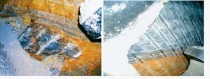
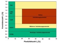
When producing the slurry the state of the rocks or soil at the face is of considerable importance as well as how they are excavated. Depending on diagenesis and/or weathering in the process rocks without mineralogical binding dissolve in slurry. On the other hand in the case of rocks with a mineralogical binding the dissolved chips largely remain within the slurry. No dispersion occurs and merely the rock meal, which formed under the bits during the excavation process, is available in the form of a fine-grained material for the plastification of slurry. In the soil-rock transition area observations during the drive indicate that the slurry is formed from a matrix, in which rock fragments with and without mineralogical binding float (Fig. 12). The fragments without mineralogical binding increasingly absorb water from the matrix during standstills during the drive, as a result of which the slurry tends to become stiffer. The required torque of the cutting wheel is consequently higher after standstills. A total of 62 slurry samples were taken behind the worm discharge and examined to determine their consistency for 2 EPB drives (samples in Fig. 12). The diagram in Fig. 13 shows that this slurry tended to remain as pasty to soft consistency.
Fig. 14 displays exemplarily the most important parameters compared in graphic form from a project for a certain excavation section. Parameters are presented, which influence the consistency of the excavated material such as the addition of water and tensides and the amount of ingressing underground water, the consistency itself as well as the technical drive parameters directly influenced by it such as torque and wear resistance of the worm. Prior to tunnel metre 4,030 and then after tunnel metre 4,120 the wear resistance coefficient of the worm and the torque divided by the cutting wheel contact pressure run practically synchronously to the calculated consistency. The latter was calculated on the basis of the rock’s natural water content and the addition of water.
However, the course between them represents a direct contrast. It is evident that on this route section the addition of water has been greatly reduced and the calculated consistency assumes unrealistically high values (partially in excess of 1). As, however, the torque and the displacement resistance would also have to increase very markedly, something which is evidently not the case, the calculated consistency for these sections cannot correspond to the existing one. This discrepancy can on the one hand be explained by the previously mentioned discontinuity in the slurry and on the other mainly by the fact that the ingressing underground water, which acts as an additional lubricant, was not taken into consideration in the calculation.
If the measured amounts of ingressing underground water are considered, then these are considerably higher for the corresponding section (up to 54 l/s). However, the question arises how this underground water could enter the extraction chamber in spite of it being filled with slurry. The explanation for this is to be found in the added foam. In theory the slurry is produced with the aid of foam and water. The foam itself consists of a mix of air, water and tenside. If the foam is added to over-consolidated soils with in part low water contents, then these soils remove the foam from the water with the outcome that the foam disintegrates and the air it contains is no longer bound. This air then collects in the roof zone of the extraction chamber on account of its low density. The formation of the air cushion in the roof could be observed during several inspections of the face. In this connection it was also determined that the water mainly flowed via fissures in the roof area of the extraction chamber. It can thus be assumed that the air cushion in the roof of the extraction chamber was unable to prevent the inflow of water from the fissures. These uncontrolled inflows of underground water are dangerous, as the ingressing water reduces the groundwater level and possibly fine-grained material can be discharged from the subsoil. Both factors can lead to undesired settlements and destabilisation above the tunnel roof.
This can only be avoided providing that water alone is added in the place of foam and conditioning is supported by means of artificial soil comprising e.g. a sand-bentonite mix with special aggregates and additives. The artificial soil possesses a pasty to soft consistency and can also be used for refilling the extraction chamber should the slurry level be dropped (e.g. for replacing tools) prior to the next driving phase.
Possibilities and Limits of mechanised Tunnelling in Soils prone to Clogging
It can generally be ascertained that mechanised tunnel driving methods with the highest rates of advance usually possess the lowest adaptability in conjunction with face stability and clogging. This applies in particular to machines with conveyor belt discharge, which are thus unsuitable in pronouncedly changing subsoil with unstable face conditions and/or clogging problems.
Under such conditions machines with worm discharge, which can be converted from dry to wet excavated material at short notice, possess the necessary flexibility. Should the prerequisites exist for improving or attaining the required slurrification by means of artificial soil in the extraction chamber, they also permit support of the face and water drainage under subsurface conditions previously regarded as being unsuitable for EPB drives.
Thus subsoil consisting of clayey soils, which especially tend to clogging on account of a lack of consolidation, tectonics and/or having been subjected to weathering processes, can be successfully driven. The prior requirement for this is, however, coordination between the prevailing subsoil and the applied driving technology. The limits of full-face mechanised driving is reached if mixed-face conditions, i.e. solid and soft rocks are encountered simultaneously in the tunnel with the outcome that blocks can be torn out or there is excessive impact on the cutting tools. This also applies to unstable subsoil conditions which are prone to convergences and also to pronouncedly abrasive conditions, which make it necessary to check and change the cutting tools frequently.
A further, general restriction with regard to mechanised driving with full-face excavation is to be found in the fact that – apart from a few exceptions – only circular tunnel cross-sections can be driven. An adaptation of the cross-sectional form to the requirements for subsequent use is then only possible with considerable effort. In spite of these restrictions mechanised driving represents a future-oriented technology, whose potential is by no means fully exploited. However, to ensure that it is applied successfully a coherent subsoil description, great experience on the part of the driving crew and engineering technology geared to the project in hand are all essential.