Finne Tunnel: Stage reached by Construction Work
Tunnel 6/2007, pp. 52 and tunnel 1/2009, pp. 18 carried reports on progress made on the Finne Tunnel. The following article presents the current stage reached by work, especially
relating to the successful conversion of the 2 tunnelling machines from slurry to open mode, relocating the 1st machine after a successful breakthrough and the installation of the tunnel invert after the conclusion of driving operations. For more detailed information
relating to the conversion of the machines please see the proceedings for the 2009
STUVA Conference, Research + Practice 43, pp. 175.
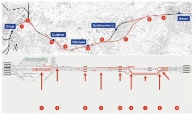
The 6,969 m Finne Tunnel is the longest on the DB AG’s new Erfurt–Leipzig–Halle route and the sole tunnel on the entire section between Munich and Berlin, whose tubes are being constructed one after the other with 2 tunnel boring machines.
The tunnel constitutes 2 parallel tubes with 10.87 m external diameter, a 45 cm thick segmental lining and cross-passages with a maximum gap of 500 m between the tubes. As a result there are 13 escape and rescue passages as well as 3 for technical purposes. In December 2006 the DB AG, represented by the DB ProjektBau GmbH, Regional Division South-east, awarded the contract to the Finne Tunnel JV consisting of Wayss & Freytag Ingenieurbau AG Frankfurt/D, Max Bögl Bauunternehmung GmbH & Co. KG Munich/D, Porr Technobau und Umwelt GmbH Munich/D and Porr Tunnelbau GmbH Vienna/A.
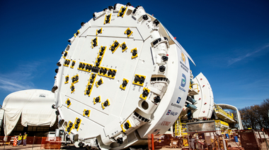
1 Converting the Machines from Slurry to Open Mode Underground
A convertible Mix-Shield was called for and also employed, which could be changed from slurry mode (tunnel metre 0– 1,550) to open mode (tunnel metre 1,551–6822), on account of the prevailing geology. The Herrenknecht AG received the contract to supply the 2 tunnelling machines in April 2007. The TBMs were deployed one after the other in the slurry mode sector. This had the advantage first of all that the separation plant technology for the first 1,500 m did not have to be set up for both machines. Secondly the recognitions gained during the first TBM passage could be taken over for the second one. Optimisations during the slurry shield drive of Machine 1 were taken into account during the assembly of Machine 2 and installations and modifications that were required carried out. The entire slurry shield components were removed and used again for the second TBM (locks, delivery and feed pumps, rock crusher hydraulic aggregate, oxygen plant, Samson compressed air control unit, telescopic pipe layer etc.).
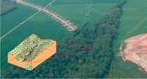
1.1 Geology and Hydrogeology
The subsoil consists of Triassic sedimentary rocks along the entire route for the Finne Tunnel. Over the first 1,500 m keuper, shell lime and coloured sandstone rocks are encountered. Intermittent layers of clay marl, lime, silt, sandstones and clays are influenced in this sector by the Finne Fault, which – in keeping with the prognosis – was to be anticipated in the form of 2 main faults and numerous secondary ones. As the underground water table present up to 50 m above the roof could not be lowered by means of a surface drainage system and a constant interchange between stable rock and pronouncedly fractured rock extending right up to loose ground in the vicinity of the faults prevailed, the drive here was undertaken in slurry mode. As the distance from the Finne Fault increased considerably better rock quality was expected and also encountered. As from TM 1,550 a surface water drainage system using pairs of drilled wells (Fig. 1) was executed in keeping with planning approval, which was and still is operated in advance of the drive so that a minimal effect on the existing groundwater conditions is assured. The fact that no water drainage was permitted by the planning approval scheme over the first 1,550 m resulted in largely stable rock being penetrated over the final 300 m (TM 1,250–1,550) in slurry mode after passing through the fault zones. The actual position for conversion was arrived at for each machine on the basis of the rock conditions encountered in situ in the transition zone to the water drainage system. As the first machine approached the scheduled conversion point the sandstones encountered were of pronouncedly varying strengths depending on their bedding. Both friable sandstones that could be crushed by hand as well as relatively hard ones with thicknesses ranging from a few cm up to several metres were come across. These were located in intermittent bedding with mudstones of varying strengths with thicknesses of between a few cm and several metres. Ingressing underground water varied between trickles and 1 l/s. Although at the most smaller break-outs occurred in the roof zone in the case of all rock variants encountered during the ongoing standard drive, no findings were available relating to protracted unsupported standstills in this geology. A hard bank of sandstone as compact as possible in the roof zone was thus favoured as the safest solution. On account of the strata dipping in the direction of the excavation the rock conditions predicted in advance could not solely be determined in the upper cross-sectional zone and above the roof by the geological documentation that accompanied the drive. As a result additional drilling was undertaken at TM 1,548. Within the largely laminated to thinly stratified, friable intermittent bedding a roughly 2.5 m thick compact, solid bank of sandstone was encountered at the level of the middle of the tunnel. A roughly 3.5 m thick red claystone layer, which was encountered beneath the subsequent tunnel floor during drilling, could be correlated with the rock profile that had so far been penetrated. On the basis of these findings the subsoil conditions between the face and the bore could be constructed very precisely. According a 10 m long “corridor” was established, in which the solid sandstone bank was anticipated in the top zone and at least a further 1 m above the top, which functioned as “roof” for the conversion position. The conversion phase progressed without any difficulty thanks to the geotechnical conditions. Whereas no changes resulted in the “sandstone roof” zone (Fig. 2, left) the claystones within the narrow intermittent bedding were softened or partially rinsed out by underground water (Fig. 2, centre). First towards the end of the standstill minor fractures occurred in the lower section of the face resulting from sandstone slabs breaking out (Fig. 2, right). These fractures probably would have led to work being impeded and to detachments in the roof.
1.2 Conversion Programme
A precise conversion programme was worked out in conjunction with the machine manufacturer, in which every step was listed. In this way it was possible to ensure that the programme was fulfilled exactly. The speedy dismantling of the slurry components, which were needed as soon as possible for starting up Machine 2, was of particular importance for converting Machine 1.
1.3 Cutting Wheel Conversion
In conjunction with the cutting wheel the process concentrated on the welding work for closing some of the openings used for the slurry mode, installing the grain size limiter, adjusting the mucking channels in the rear sector of the cutting wheel as well as starting up the muck ring and the corresponding machine belt. In contrast to conveyance by slurry mode, the flow of material now had to take place via the shield’s base to the muck ring in the middle of the shield. On account of the prevailing situation it was decided to undertake conversion entirely from the rear. The determining factor here was to ensure that as few members of the crew as possible were exposed to the unsecured area in front of the cutting wheel in order to create the necessary conversion chamber. The more complicated execution of the welding work represents a disadvantage here, first of all resulting from hampered accessibility (overhead welding) and secondly owing to the more complex form of the welding seams (Fig. 3). In some cases these had to be executed as dipping welding seams protected by gas. In addition V-seams were used to an increasing extent instead of the usual fillet seams. Subsequently all welding seams were subjected to the usual testing process. Special ventilation was required for the work in the cutting wheel sector so that the welding gases could be extracted. Pressurised ventilation with several fans installed in the cutting wheel sector was employed.
1.4 Conversion in the Shield Sector
In the shield sector the removal of the slurry components such as for example the compressed air control unit and the 2 locks was accorded priority. The 2 locks first had to be dismantled to enable further work to be undertaken. The locks were transported by rail to the erector, attached to it and swivelled downwards (Fig. 4). The locks were carried to the end of the back-up system via the segment feeder and transported outside by train. The equipment for the drilling units was set up in the sector vacated by the locks.
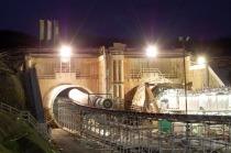
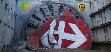
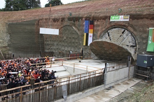
2 TBM Drive 1: Breakthrough and Moving the Machine
After the breakthrough was accomplished on September 30th, 2009 (Fig. 5), the machine had to be moved forward on the existing floor of the sonic boom structure so that the TBM and back-up system were located completely outside the tunnel. This was essential to clear the tunnel as soon as possible (track, emergency pathway, pipes etc.) so that work could start on installing the concrete floor. Only 2 weeks after the breakthrough the tunnel had been completely cleared and cleaned. Following a further 2 weeks the segments in the floor sector had been cleaned up to such an extent that work on installing the invert concrete could be started. As is evident from Fig. 5 the machine moved into the existing construction pit: the breakthrough wall was secured by a back-anchored shotcrete wall. A lean concrete block was installed in front of the wall, in which the TBM cut the shield cradle. A moving structure had to be installed to pull the machine a further 80 m to the front. Towards this end thrusting beams were concreted on the base of the sonic boom structure, which later were integrated in the floor set-up of the final structure. Two abutment blocks were concreted at the end of the moving structure (Fig. 6). A cross-beam was assembled behind the shield machine (Fig. 7), which was suspended from the abutment blocks via threaded rods. The TBM pressed against the cross-beam by means of the thrusting jacks and moved forward by a stroke (2 m). The jacks were then retracted, the rods shortened so that the cross-beam was situated directly behind the shield so that it could be pushed forward by a further 2 m. Using this system it was possible to renounce the laying and assembling of floor slabs so that it was possible to move the TBM in a relatively short time.
3 Installing Floor Concrete
The prerequisite for further work in the tunnel (cross-passages, benches) once the breakthrough was completed is the installation of the tunnel floor, for which roughly 4 m² of concrete per running metre is needed. The following main problems resulted in this connection: in its initial state the tunnel represents a 7 km long one-way street, in which vehicles can only drive in the curve of the segments. It is impossible for them to turn or pass each other. Passing traffic is not possible on the tunnel floor (some 5.5 m wide at its centre). Turning can only be accomplished by special vehicles. In order to be able to use conventional trucks the following system was set up: the work designed to create the floor was accomplished in a weekly cycle using a kind of pilgrim step process, operating on the section completed the previous week. At the start of the week the finisher is set up 500 m behind the completed floor in the tunnel. The section of floor is then completed from that point so that at the end of the week 500 m has been completely concreted (Fig. 8). Trucks drive over the floor completed the previous week, which has a turntable installed at the end of it, which can rotate a three-axle truck. The truck reverses over a ramp onto the segments, driving at the most over the previously mentioned 500 m to the finisher, dumps the concrete and moves away. In this way it is possible to complete between 500 and 600 m of floor in a weekly cycle with a single shift. The concept is displayed in Fig. 9. The breakthrough for the 2nd TBM is planned in the course of February/March 2010. In addition work on the cross-passages was due to commence in January 2010 using the NATM.