Adjustable flexible segment lining
In tunnelling, geological ground conditions with high-pressure areas caused by weak rock conditions or high layers of loose rock continue to present a challenge. Heintzmann of Bochum, Germany, has developed the adjustable flexible segmental lining method using compressible elements. This method was tested successfully in the second tube of the Tauern tunnel.
Mechanical tunnelling has gained increasing importance over the past years. This tunnelling method, e.g. with a shield machine, provides a high degree of security for the tunnelling team. With homogeneous, continuous rock conditions, automation provides high tunnelling speeds and cost efficiency. Even though special measures may have to be taken under poor rock conditions, this tunnelling method is becoming increasingly viable.
However, geological ground conditions with high-pressure areas caused by weak rock conditions or thick layers of loose rock still lead to problems. Such rock conditions may adversely impact mechanical excavation and may even interrupt excavation or cause prolonged standstills. If a machine gets stuck under such conditions, cost- efficiency becomes questionable.
In conventional tunnelling, blasting or when using excavators as in the NATM, it is possible to continuously adjust the segment lining system to the actual geological formations. Through the use of side-walls or temporary top heading inverts as well as increased use of anchors, varying anchor lengths etc., it is possible to adapt the lining method to the rock and excavation situation. In addition to the known tunnelling variants, flexible (compressible) elements have been developed for problematic pressure zones, creating rock deformation routes and reducing rock tension, thereby reducing pressure until an equilibrium of tensions and forces is achieved. The second tube of the Tauern tunnel could be excavated successfully in extreme fault zones not least thanks to the flexible elements. Using innovative honeycomb elements, Bochumer Eisenhütte Heintzmann has succeeded in creating a flexible lining resistance that is adapted to both the local conditions and the shotcrete hardening process.
There have been few attempts at controlling rock pressure conditions in mechanical excavation. Segmental lining methods are currently limited to compensating high pressure and shifts in the annular gap or indicating additional deformation potential through the use of ribbed segments. In mechanical tunnelling, there are currently no flexible (compressible) elements of the type used in conventional tunnelling. There are theoretical approaches, but no practical experience.
At the bauma construction machine fair in early 2010, Bochumer Eisenhütte Heintz-mann, a steel manufacturing company based in Bochum, Germany, introduced a concept for flexible, adjustable lining segments based on the honeycomb flexible (compressible) elements.
New technology
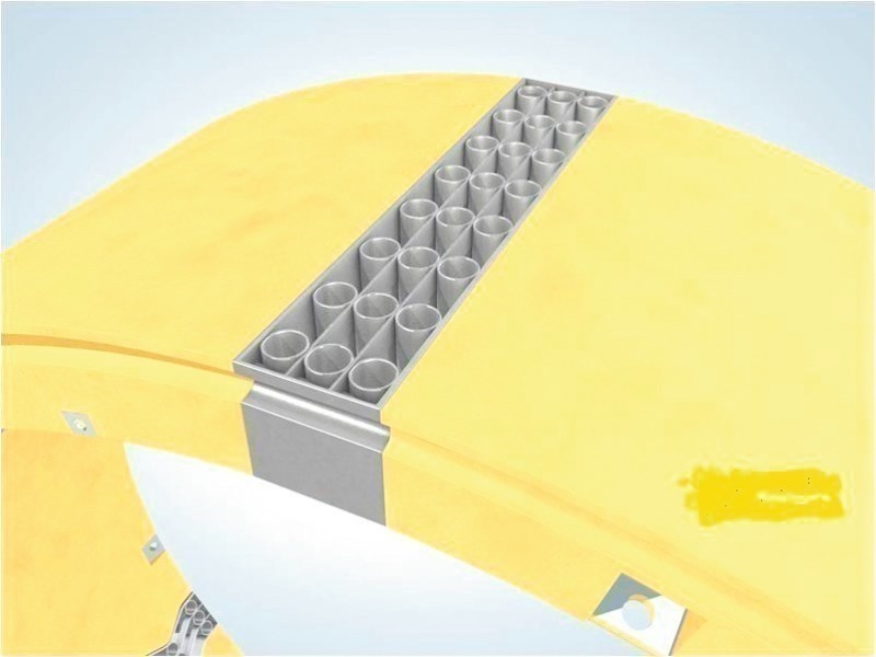
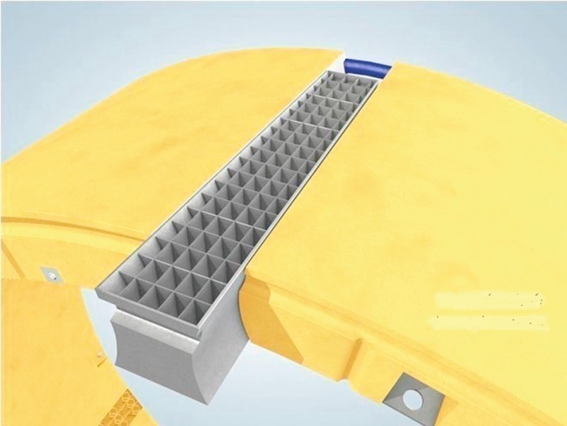
In situations with dynamic, high pressures, fault zones or significant convergence, the segments should be able to yield to the rock, avoid the pressure exerted by the rock and reduce the circumference by means of flexible elements integrated in the segment contact surface. Such flexible elements were developed by Bochumer Eisenhütte Heintzmann based on their experience with honeycomb compressible elements in conventional tunnelling. The resistance of the flexible elements is designed to take up the rock impact in order to reach equilibrium before the reinforced concrete is destroyed. Fig. 1 to 3 show different variants for possible flexible elements.
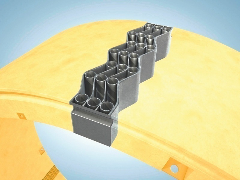
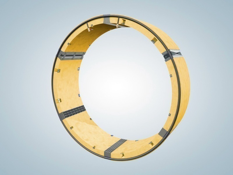
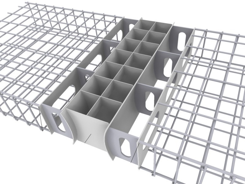
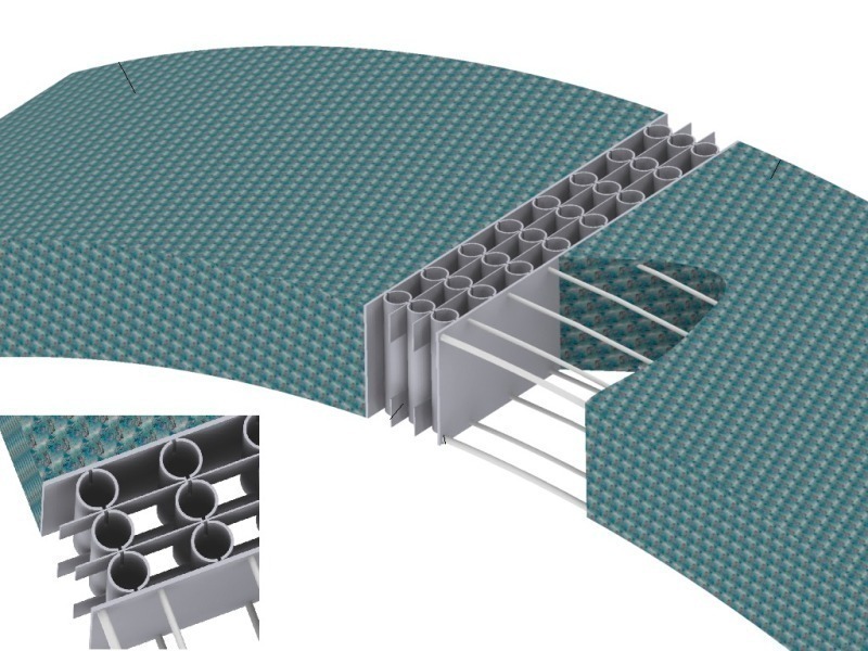
Similar to the compressible elements used in shotcrete lining, the steel elements are designed as honeycomb-type tubes or grids, allowing for adjustability (increasing/reducing the size of the ring). The adjustable/flexible elements are made of steel and are positioned between two pressure or contact plates; they are adapted to the dmensions of the segment. Together with the segments and the conical keystone they form a complete segment ring. The flexibility is achieved using tube segments or grid or coffered structures. Adjustability is achieved using longitudinal or double wedges.
The elements can be arranged in any order. They can be incorporated into the segment ring design according to the desired action. The resistance of the flexible elements is designed to take up the rock impact and to deform in order to reach equilibrium before the reinforced concrete is destroyed. With this system, it is possible to combine the elements required like building blocks. The system does not need to be adapted to TBM technology because segments are handled in the same way as segments with no flexible elements.
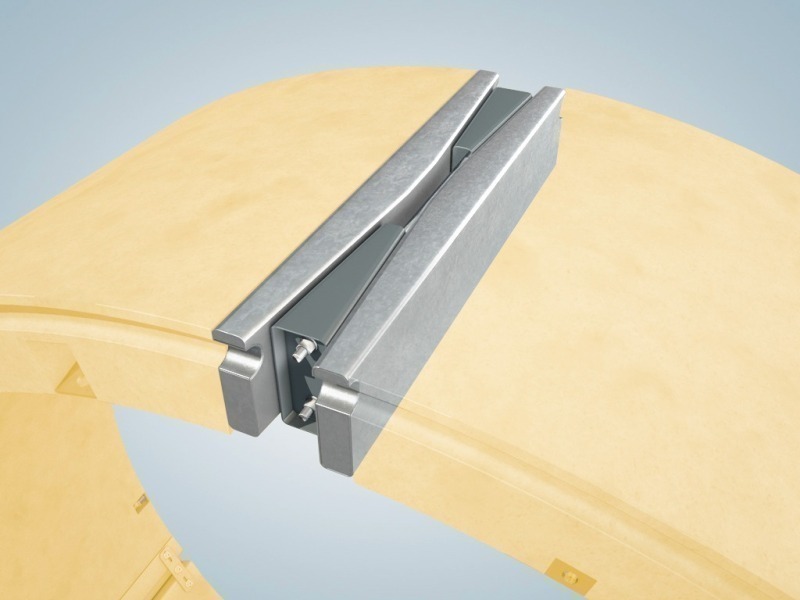
Fig.s 4 and 5 show different designs for adjustable flexible elements.
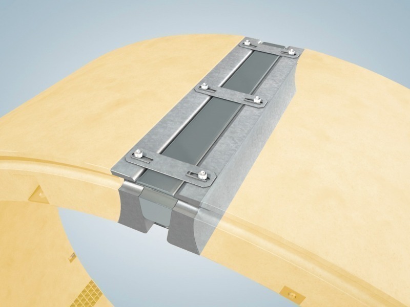
As a rule, the flexible and the adjustable flexible parts can be incorporated into the segment concrete reinforcement on one side or on both sides using the building block system (Fig. 6). In this case, the concrete faces are screwed together. In extreme cases, all components can be screwed together. The faces are fitted with embedded sealing joints.
There are various fastening options designed to ensure that the segments can move in longitudinal direction. While allowing spatial movement, these options position the segments with respect to each other (Fig.
7 and 8).
Tightness of the longitudinal joints is ensured today by means of a trapezoid-shaped rubber seal with air chambers which is embedded in a groove running around the segment. The pressure exerted by the screw connections is sufficient to achieve the degree of tightness required.
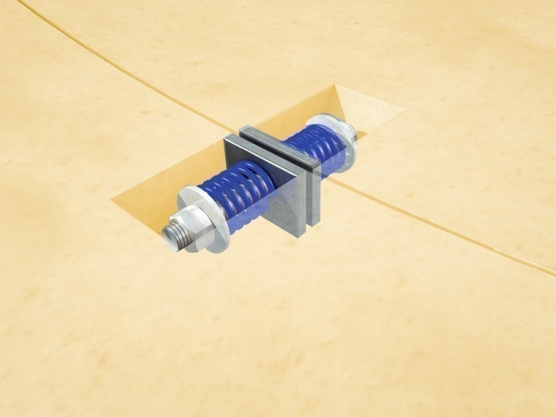
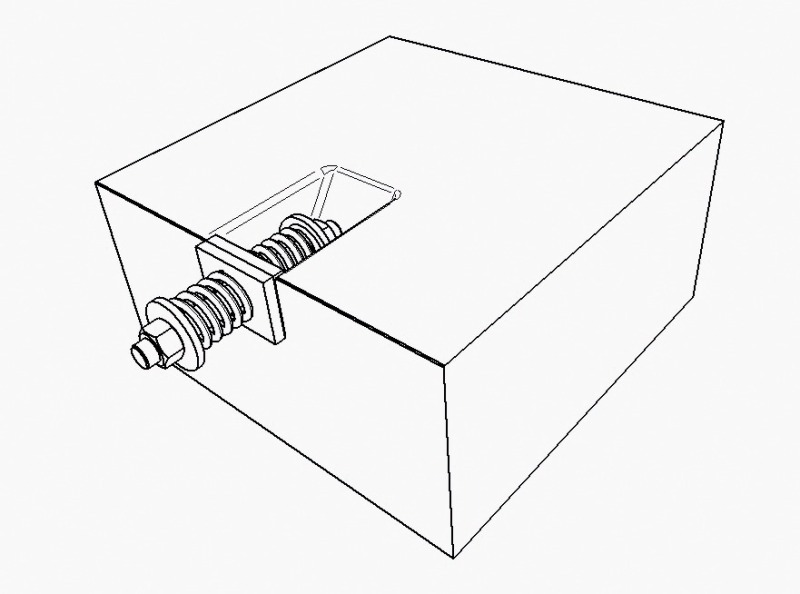
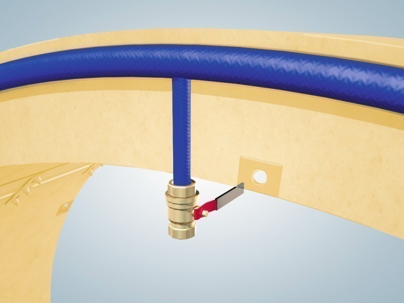
This method may not be adequate if segments move relative to each other. When there are extreme offsets between segments, they should be fitted with a rubber tube seal. This rubber tube seal can be inflated with a medium, similar to a bicycle tube (Fig.. 9). It would be possible to press the segments together later using a valve system. Using this type of sealing, it would no longer be necessary to depend on the joint pressure between the segments alone. Tests of this are already being carried out.
Static requirements, element design and tests
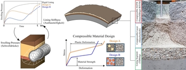
The static analysis initially determines typical loads for the segment lining ring and takes into account pressure conditions for tunnels at great depths or tunnels with high loose rock loads.
Geomechanical conditions are used to calculate the cutting forces present in order to determine the load conditions of a segment. Displacement and lining resistance are defined according to the characteristic curve method. As the support pressure is reduced, the rock behaves elastically until a critical lining support pressure is reached. However, if the pressure goes below this threshold, the material begins to become plastic.
The functionality of the flexible honeycomb elements in the segment lining can be described as creating an additional annular gap for rock deformation. By using flexible elements in segment lining, deformations in the system can be compensated and radial tensions reduced. Following compression of the flexible element, the segment must provide the necessary resistance, while the honeycomb loses its functionality following complete compression. It will transmit the normal forces present between the different segments. The flexible elements are designed and dimensioned according to the characteristic that has been determined.
In order to simulate these theoretical approaches in a realistic test, the flexible elements must be pre-dimensioned and adjusted following calculation of the forces to be expected in the segment ring. The lining resistance of the elements must be designed to meet the static specifications in practice (Fig. 10 and 11). It must be ensured that the deformation path corresponds to the lining resistance. Ruhruniversität Bochum is currently testing different element designs.
Conclusion
The building block system with its different element variants is able to continuously adapt to planning and static requirements. Thanks to the wide range of design options and shapes, the system can be adapted to segment requirements in any situation.