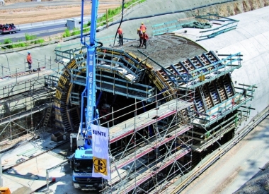
Hahnenkamp Tunnel: Tunnel Outer Walls and Trough Walls largely concreted without Anchors given constricted Space Conditions and high Groundwater
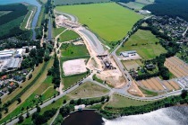
A roughly 11.5 km long, 4-lane route runs to close the gap between the A 2 and A 30 motorways – approx. 2 km as federal highway 61 and 9.5 km as the A 30 motorway and serves to relieve the centre of Bad Oeynhausen. Until the first vehicle uses this route, 3 hubs as well as 26 bridges and crossovers have to be produced, including 2 major structures passing over the Werre. The 450 m long Hahnenkamp Tunnel built by cut-and-cover represents an important part of this construction scheme.
In situ Concrete Structure under tricky Conditions
The actual tunnel bore is to be produced as a 2-cell frame structure for the 2 separate, directional carriageways. Trough structures with lengths of 178 m in the north and 138 m in the south are to be set up directly connected to the tunnel. The tunnel roughwork costing around € 25.5 million is being carried out by the Tunnel Hahnenkamp JV.
As far as the formwork is concerned, the tunnel represents a great challenge for the topographical circumstances and the high prevailing groundwater pose high demands on the tightness of the structures. Owing to the drainage and the constricted space conditions the outer walls of the tunnel and the trough walls are being concreted anchorlessly against the shoring system.
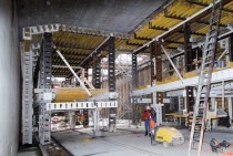
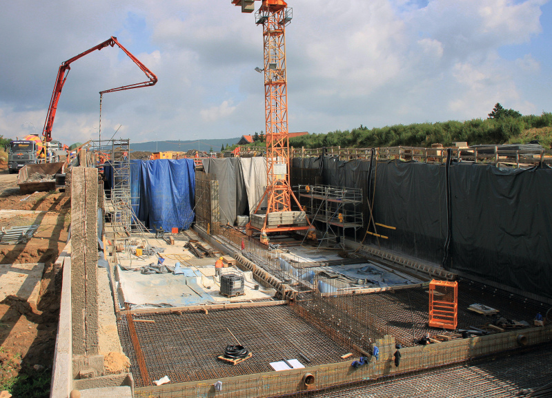
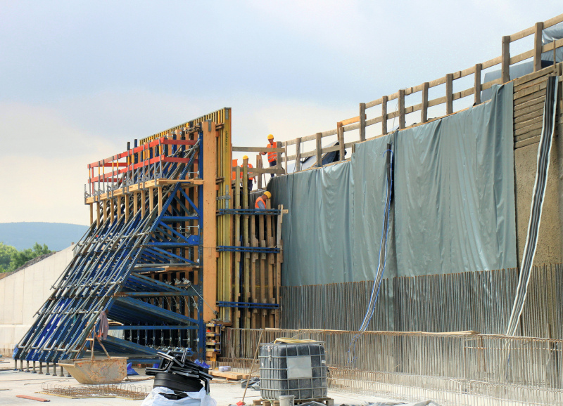
The tunnel itself is being produced as a part-monolithic structure in other words, the walls and floor are without working joints (Fig. 1). Given dimensions of 22.60 m wide, 8.22 m high, a central partition wall and wall and floor thicknesses of up to 1.20 m no straightforward task. As a result, the Adam Hörnig Company as specialist for in situ concrete construction is relying on Doka GmbH.
From the very outset, the construction site insisted that the formwork had to function without anchors. This means that a free clearance profile for moving personnel had to be kept available at all times. The project engineers from Doka headquarters at Maisach came up with a technically mature and commercially viable formwork concept in keeping with this requirement.
Tunnel Production in a weekly Cycle
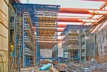
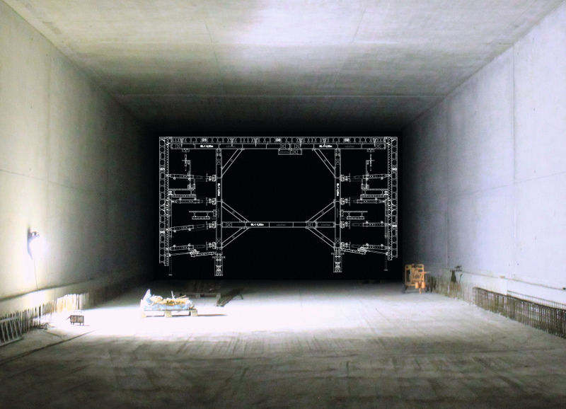
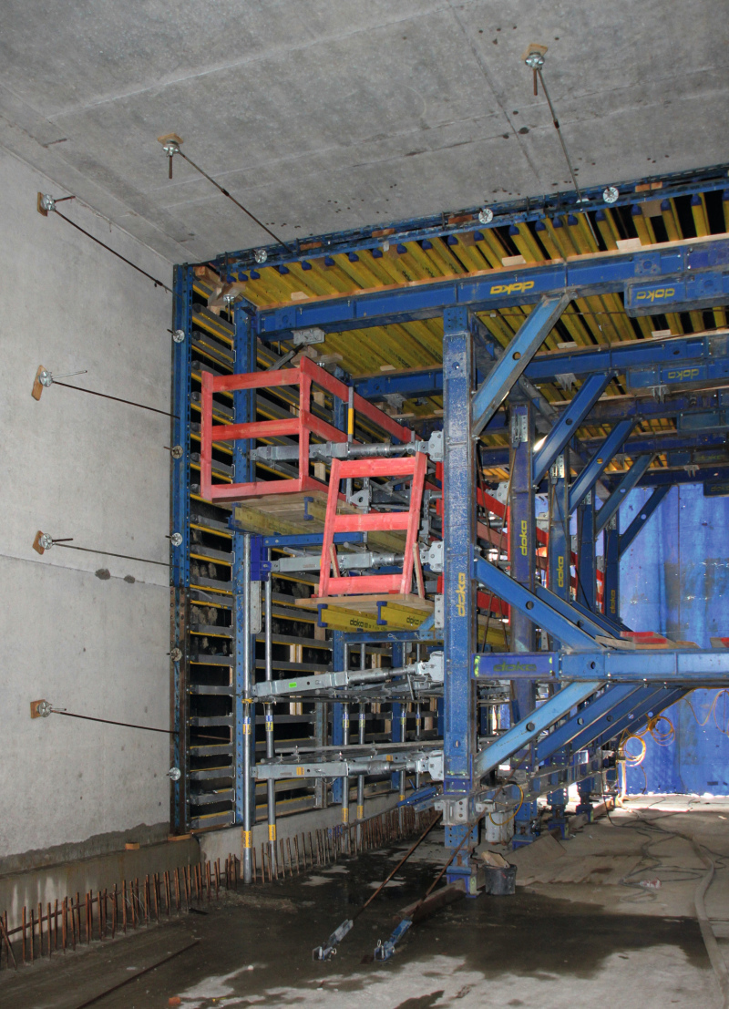
The tunnel itself is being produced in 45 weekly cycles each 10 m in length. For this purpose, a 10.5 m long formwork carriage is deployed for each of the 2 cells. Its basic structure largely consists of the modularly constructed SL-1 scaffolding system (Fig. 2). 10.50 m long elements, which the Doka-Fertigservice preassembled from the Top 100 tec and Top 50 scaffolding systems, serve as the actual wall and floor formwork.
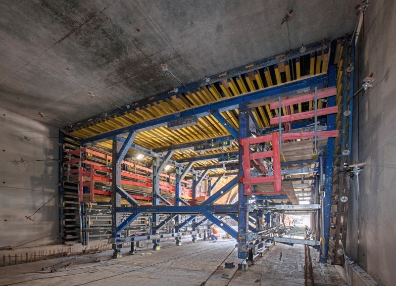
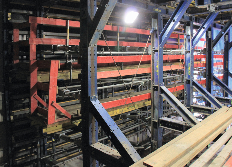
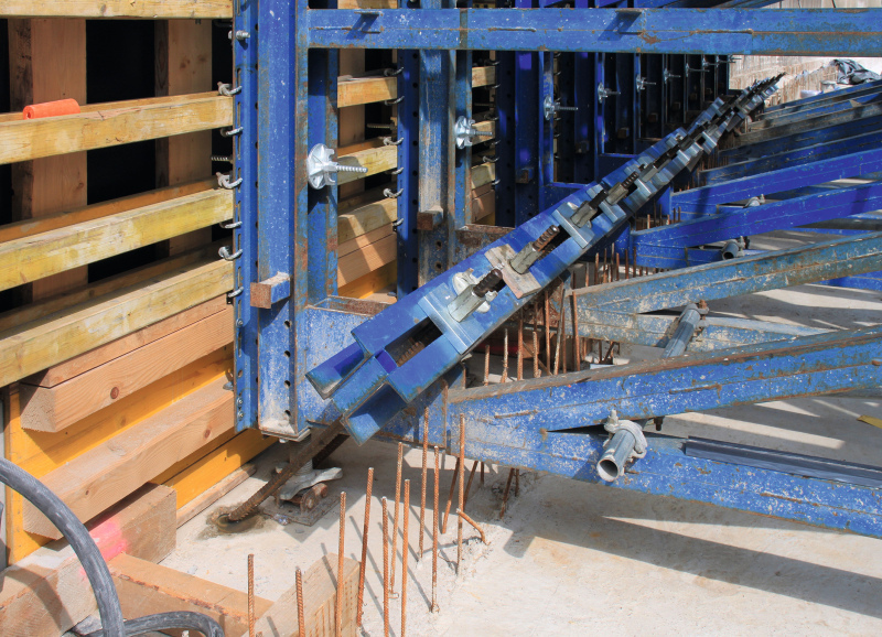
The wall formwork is height-adjustable for straightforward stripping. It constitutes especially stable I tec 20 composite formwork beams. They can sustain roughly 80 % higher loads than the well-known Doka full wall beams with the blue end reinforcement. In this way the formwork carriage from the SL-1 scaffolding system can be optimally loaded statically (Fig. 3). The transference of high loads from the wall and floor thus only calls for 5 cross segments per carriage.
In order to avoid anchorage of the wall formwork, the formwork carriage transfers all prevailing loads from the fresh concrete pressure horizontally into the opposite side of the tunnel. Thanks to the uniform concreting of the outer walls and the central wall the horizontal forces in the static system cancel each other out.
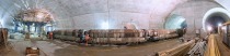
Although a unit weighs 53 t, it can nonetheless be easily moved. For relocation purposes, first of all the height of the wall formwork units are adjusted by some 7 cm (Fig. 4). Subsequently the entire structure is lowered by 14 cm on travelling rails. In this way, there is sufficient room for manoeuvre for stripping so that the 2 formwork carriages can be moved forward on flanged wheels for the next section – without complicated assembly operations. In this way, 10 running metres of tunnel are produced week-by-week (Fig. 5) according to schedule.
Concreted single-faced against the Shoring System
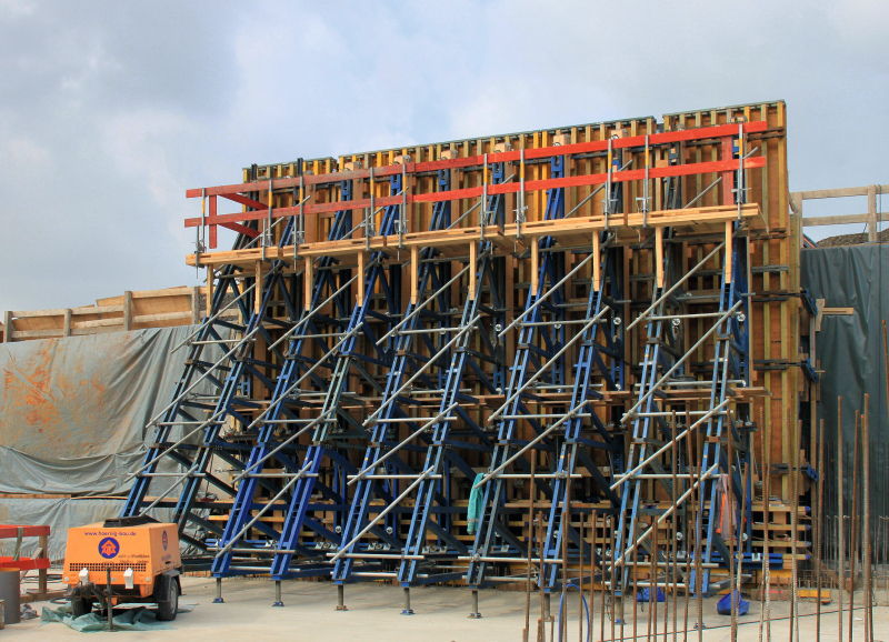
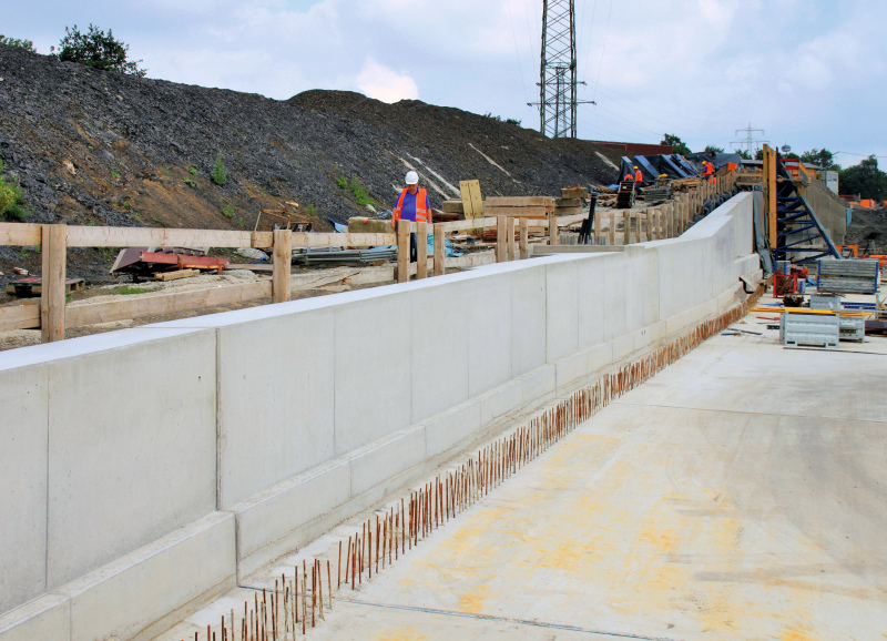
The 1.8 to 9 m high walls for the trough structures are being created using Doka formwork (Fig. 6). They are mainly concreted single-faced against the shoring. Rentable system components comprising FF20 beam formwork and Doka supporting frames are combined here. Both the supporting frames as well as the FF20 beam formwork can be lengthened or shortened in keeping with the development of the wall height.
The Doka project engineers developed a clever solution for coping with the wall thickness projections of 15 or 50 cm, which occur singly or even twofold within a formwork element while still ensuring that only a minimal quantity of formwork is required (Fig. 7). The FF20 system formwork is coupled at its base and combined with project-specific formwork from the Doka-Fertigservice. Force-transferring laminated wooden beams save on unwieldy box-outs and enable practically unhampered access to the rear side of the formwork, something which makes the alignment and adjustment operations considerably easier. Two 20.0 mm diameter inclined anchors per supporting frame transfer the fresh concrete pressure that ensues into the previously concreted base (Fig. 8).
The fresh concrete pressure constantly causes deformations at the upper end of the single-faced formwork units. For Doka supporting frames, these deformations are provided in the Doka user manual for various influencing, fresh concrete pressures and concreting heights. The experts at the Hahnenkamp Tunnel tilt the formwork to the front when setting it up so that the finished wall subsequently stands absolutely perpendicular.
The FF20 beam formwork is provided with a coated Plex plate for good exposed concrete results. Altogether around 50,000 m³ of concrete of quality C 30/37 has to be installed properly. The concrete presents an impressive picture just as in the tunnel sections (Fig. 9). However in daylight the good impression is even more evident than in the closed tunnel.
On the tunnelling site at the Great Bend of the Weser in Bad Oeynhausen – in the vicinity of the Porta Westfalica – only 430 m² of tunnel formwork and 289 m² for the trough walls are needed. An extremely economic amount for the altogether 18,360 m² of tunnel formwork and 3,800 m² of trough walls consisting of in situ concrete.
Collaboration as Partners
The experienced construction site personnel put together the prefabricated formwork that was supplied in the presence of a well-versed Doka foreman to produce ready-for-use units. Given so few knowledgeable staff, it is wise to resort to the Doka-Dienstleistung “formwork preassembly” for such purposes. Doka the complete Assembly Contract
The Doka foreman is also willing to provide answers to specific questions and provide tips at a later stage – making for good collaborations as partners. A further service, which Doka offers to an increasing extent, is “taking back formwork on site”. In this case, the rented equipment is taken back directly on the construction site by Doka staff and at the same time a binding return clause is invoked. In this way, agreement prevails over the quantity and state of the material. A further advantage: efficient application of the site personnel and saving costs thanks to a reduced leasing period.