Minimal Settlement under 18th Century Jaipur City Gate
 Quelle/credit: Robbins
 Quelle/credit: Robbins
 Quelle/credit: Robbins
 Quelle/credit: Robbins
 Quelle/credit: Robbins
 Quelle/credit: Robbins
 Quelle/credit: Robbins
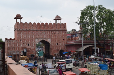
Jaipur, India’s tenth most populous city, is a cultural melting pot of 6.6 million people. The city’s heart is encircled by a wall six meters high and three meters thick, with seven gated openings. Built in 1727, the walls and many of the old city streets were painted pink and remain so today, giving Jaipur the nickname of the “Pink City”. It is below these delicate and iconic structures that Jaipur’s first Metro, Line 1, will travel. The above-ground Phase 1A runs 9.63 km from Mansarovar to Chandpol Bazaar with nine stations, and was opened to the public in June 2015. Phase 1B is tunneled and consists of 2.3 km and two stations running below the walled center. The completed Line 1 is expected to open to the public in 2018.
Geology and Gate Structures
Chandpol gate, one of the seven, is directly above the bore path for the Line 1 extension, and serves as a historical landmark (Fig. 1). Contractor Continental Engineering Corporation (CEC) was tapped to excavate twin tunnels 2.3 km in length with a 5.8 m inner diameter. The alignment of the tunnels traversed geology that can be generally divided into two types. The first type is composed of a mixture of silty sands and the second type of silty sands with minor quantities of clay and gravels. Based on the observed N-values, which are greater than or equal to N = 41, the strata can be described as relatively dense. Each soil type is either dominated by fine sands or a fairly equal mixture of silt and sand. The geology containing clay is still dominated by the sands and silts, with less than 10 % clay content. The complete length of the underground section of the project is above the water table so there were no concerns regarding ground deterioration or running sand due to water ingress. Due to the low moisture content of the soil it was considered to be non-plastic.
In general terms, it was not anticipated that the geology in itself would cause any major problems to the TBM tunneling operations (utilizing two EPBs). However, the geological conditions coupled with the extremely low overburden in the area of the launch shaft (especially the section passing beneath Chandpol gate) was cause for major concern. The construction materials of the walls and gate consist of irregularly-sized pieces of stone cemented together with lime mortar and faced with a sand and lime mortar render. The foundations consist of irregularly-sized stone blocks that provide little to no resistance to tunneling-induced settlement. Contractually the allowable limit for surface settlement was set at 4 mm. However there was also an Indian archeological law in place that made the stakes a bit higher: “whoever destroys, injures, mutilates, defaces, alters, removes, disperses, misuses, imperils or allows to fall into decay a protected monument, or removes from a protected monument any sculpture, carving image, bas-relief, inscription or other like object, shall be punishable with imprisonment for a term which may extend to six months with a fine which may extend to five thousand rupees or with both” [1].
Rebuilt Machines
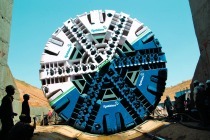
The contractor opted to refurbish its two 6.52 m diameter Robbins EPBs originally used for their contract BC-16 on the New Delhi Metro. On that project, one of the two machines achieved a project record of 202 m in one week—faster than any of the 14 other TBMs boring the metro line. The machines completed five different drives by 2009.
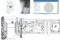
The Robbins EPBs were refurbished in India, and customized for the Jaipur project. The original machines for New Delhi (Fig. 2) bored a straight tunnel and did not require active articulation, but a 430 m radius curve in Jaipur necessitated that the machines be articulated. The shields were essentially cut in half and another section put in to form articulation joints in the contractor’s casting yard. In addition, new a+b grouting systems were installed as well as sophisticated tunnel guidance systems to monitor each machine’s position.
The final specification of the refurbished machines is shown below.
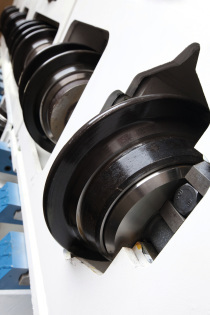
·Spoke-type cutterhead equipped with soft ground tools; opening ratio of 60%
·Excavation diameter: 6550 mm
·Maximum cutterhead torque: 5148 kNm
·Exceptional cutterhead torque: 6178 kNm
·Number of thrust cylinders: 16
·Thrust cylinder stroke: 1750 mm
·Maximum operating main thrust: 32 000 kN
·Active articulation
·Number of articulation cylinders: 12
·Articulation cylinder stroke: 250 mm
·Maximum articulation thrust: 32 000 kN
·Screw conveyor internal diameter: 900 mm
Settlement Reduction Planning
Several options were considered regarding ground consolidation by pre-injection, both beneath the gate and throughout the zone of influence either side of the gate. However, concerns were raised that injection operations may in fact disturb the dense silty sand, resulting in a reduction of its structural integrity rather than improving its properties. Finally, it was decided to restrict treatment operations to sealing and filling of the voids and cavities in the stone foundations of the gate. This was achieved by injection of OPC grout pumped under low pressure.
Control of surface settlement and vibrations would now be the main mitigation measure in preventing damage to the gate. This would be achieved by undertaking a strict regime of surface monitoring, the results of which would then be conveyed directly to the TBM operator’s cabin to enable decisions to be made on the necessary adjustments to the TBM operating parameters.
A traditional manual surveying system consisting of a comprehensive array of surface datum points was installed above the alignment of both tunnels. The frequency of the surface monitoring points varied, but leading up to and past the gate’s zone of influence up to four points were installed per meter of alignment for each tunnel. An automatic system consisting of twelve prisms installed on each side of the gate structure, vibration monitors, and eight borehole extensometers gave constant readings that were evaluated and recorded via a computerized control station. Existing cracks in the structure were monitored via traditional glass strips and crack meters.
Machine Launch
The first machine was launched in early May 2015, and would serve as a test for the challenges ahead. The Robbins Company provided a team of key personnel including TBM operators to supervise the boring operations until both machines had passed beneath Chandpol gate and beyond the zone of influence.
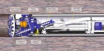
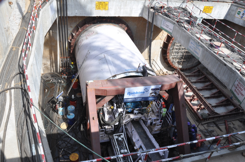
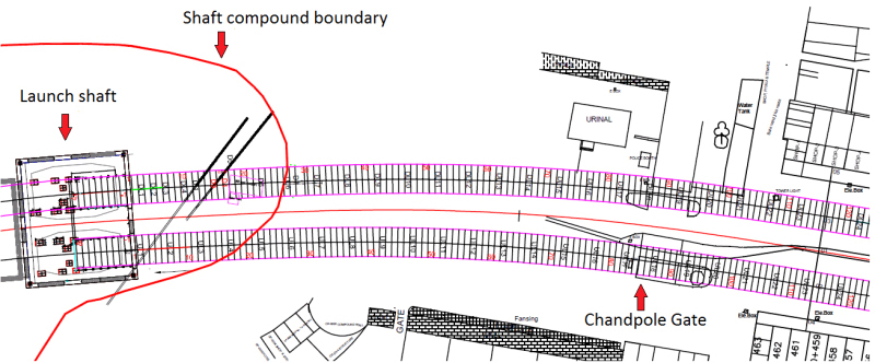
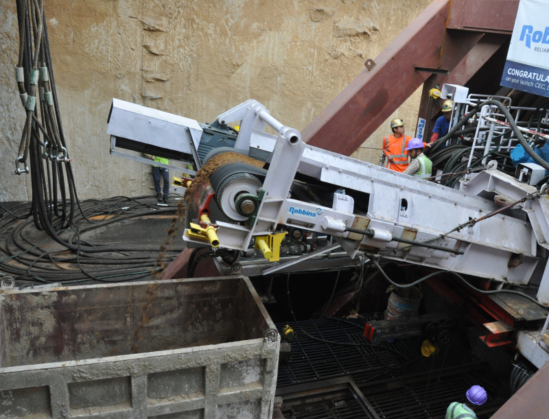
Due to the restricted site footprint, the size of the launch shaft dimensions would only facilitate a short startup procedure. This involved the TBM back-up gantries being placed on the surface adjacent to the shaft and the TBM operating via umbilical cables (Fig. 3). The plan for each TBM was to bore 85 m by this methodology and cease boring 10 m from the zone of influence, which was a total of 20 m from Chandpol Gate (Fig. 4). The 85 m of boring facilitated the installation of all back-up gantries; hence, the TBM would be fully functional prior to boring beneath the gate. It also allowed room for installation of a rail switch in the tunnel portal area.
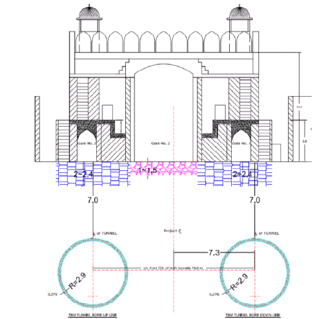
Overburden ranged from 5.8 m at the launch shaft to about 10 m at the exit shaft, but below the gates the tunnel passed just 4.5 m beneath foundations (Fig. 5). Settlement below the gates, at a point about 97 rings into the drive, had to adhere to the 4 mm limit. To tackle the challenge, Robbin Field Service defined basic TBM operating parameters that were then fine-tuned based on results from real-time surface monitoring.
Remedying excessive Heave
During the boring of rings 15 to 27, surface monitoring results indicated that heave of over 100 mm and settlement of up to 50 mm was occurring on the surface above the TBM. Initially the source of the problem was not identified as the monitoring results suggested that the heave was occurring approximately five meters behind the TBM cutterhead rather than in the area directly above the cutterhead as would normally be expected. Also, this section of the tunnel alignment was within the boundary of the launch site compound and passed beneath recent excavations that had been carried out to enable re-routing of surface storm drain culverts and services. Heavy plant including cranes and muck shifting trucks were operating over the same area of ground so it was assumed that the movement of this equipment was causing surface ground movement in the area of the backfilled excavations, which was resulting in erroneous monitoring results. Despite this assumption numerous adjustments were made to boring parameters, including TBM advance rate, EPB pressure and cutterhead RPM in an attempt to minimize the excessive heave.
Once the TBM had passed this area and similar monitoring results were still being recorded it became clear that the heave/ground movement was in fact being caused by the TBM; hence, further investigation was carried out. This was in the form of continuous monitoring of the surface directly above the TBM during the boring of the following five rings. The results revealed that the heave was occurring immediately above the articulation joint of the TBM. After detailed analysis and discussion, it was thought that the most probable cause of the ground disturbance was that the articulation was causing the rear section of the TBM to apply forces against the ground in an upward direction, resulting in the heave. It is worth noting that the results also showed that the pattern of disturbance was similar to that of the bow wave of a boat, wherein the greatest amount of heave was recorded on the inside of the curve and subsequent settlement or troughing was greater on the outside of the curve.
To prove this theory, the articulation was gradually reduced over the course of the following five rings of boring while continually monitoring surface movement. The results from the monitoring confirmed that as the articulation was reduced the heave on the surface also reduced; however, it became clear that the machine could not be steered effectively without the aid of articulation. The problem now faced was how to steer the machine without utilizing the articulation.
The original methodology for steering the unmodified machines was via the use of copy cutters for over-boring and applying variable thrust forces through the main thrust cylinders. The machines still possessed both capabilities but it had been decided by the contractor that the copy cutters were now redundant due to the addition of the articulation systems; hence, they had been blanked off with steel plates. It was not possible to remove these plates from inside the cutterhead so a small shaft was excavated above the cutterhead, the plates were removed and the copy cutters commissioned.
There now only remained 30 m of boring before the machine stopped to install the backup gantries plus a further 10 m of boring before the machine entered the gate’s zone of influence. During this time the operating parameters of the machine had to be refined to the point where boring operations could be carried out while meeting the contractual requirement of no more than 4 mm of surface settlement. The initial 9 m of boring after the restart would not give conclusive results as the whole of the TBM needed to pass through the overbore created by the copy cutters before their effect would be fully realized.
The TBM was now beneath a busy arterial road, which meant that continuous monitoring of the data points on the surface could not be carried out. However, due to the short start-up and restricted length of the TBM conveyor (Fig. 6) only one muck car could be used at a time. Four muck cars were required to complete the excavation of a 1.2 m ring; hence, a regime of monitoring the surface points after every 300 mm of boring was initiated by intermittently holding up traffic. The results of the monitoring were relayed directly to the TBM operator, who then adjusted the TBM parameters accordingly. The baseline starting parameters were 1.5 bar of face pressure, cutterhead speed of 1.3 RPM and TBM advance rate of 15mm/minute. The copy cutter was deployed from face positions 10 o’ clock to 4 o’clock and set to overcut 50 mm. These parameters were then refined over 30 meters of boring. When the TBM stopped after completion of ring No. 70 to install the gantries, the face pressure had been reduced to 1.4 bar, cutterhead speed was 1.2 RPM and TBM advance rate was maintained at 15mm/minute. The copy cutter was being deployed from the 9 o’ clock position through to the 5 o’ clock position and overcutting 50 mm. Pumping of bentonite through the cutterhead and around the profile of the shields had also been introduced to reduce frictional forces between the TBM shields and ground. The results were very positive: the maximum heave above the machine was 3 mm, and the maximum heave/settlement for the preceding seven rings was restricted to 1 mm.
Boring beneath Chandpol Gate
The key to boring beneath the gate without any adverse effects had always relied on refining the TBM operating parameters before the TBM reached the zone of influence. As this had been achieved, these parameters were maintained after the restart and similar results were achieved up until ring No. 75, where surface heave increased slightly. Due to the increase in heave the EPB pressure was reduced to 1.2 bar and cutterhead speed to 1.1 RPM. These changes reduced the heave to within tolerance. Although vibrations levels were minimal, as the TBM approached the gate the cutterhead speed was further reduced to 1.0 RPM to minimize the risk of damage by vibration. The machine passed beneath the gate and through the zone of influence without incident using these parameters. The maximum recorded settlement in the vicinity of the gate was 2 mm and absolutely no adverse effects were sustained to the gate. The lessons learned on the first drive were applied to the second drive and TBM II also passed with minimal settlement and no damage to the gate.
Conclusions
Relying on the latest available technology may not necessarily be the best option for all underground projects. The lessons learned on the Jaipur Metro project showed that active articulation, which is considered to be the most up to date and effective technique for steering a TBM, actually caused excessive ground disturbance due to the extremely low overburden and non-plastic nature of the soil. In this case the older methodology of steering the TBM by means of utilizing copy cutters and differential forces on the main thrust cylinders proved not only to be the most effective, but the only viable option. These points should be considered during TBM selection for future projects with low overburden in non-plastic soils.