Advance Exploration accompanying the Drive: Mixshield with Vision
The demand for the highest possible amount of safety in tunnelling and at the same time
a construction sequence, which is as frictionless and speedy as possible, represents the motivation for the development of corresponding exploration technologies. These enable potential dangers to be assessed in advance so that corresponding reactions can be under-taken. For this reason the Herrenknecht AG developed the Seismic Softground Probing (SSP) advance investigation method, which has been used for numerous projects since 1997.
Since the introduction of the SSP system, which is highly complicated in its manner of functioning and reacts sensitively to external disturbing influences, it has become a sophisticated and ambitious target to deploy a geophysical advance exploration system on a tunnel boring machine (TBM). Consistent further developments and optimisations of all SSP components are thus all
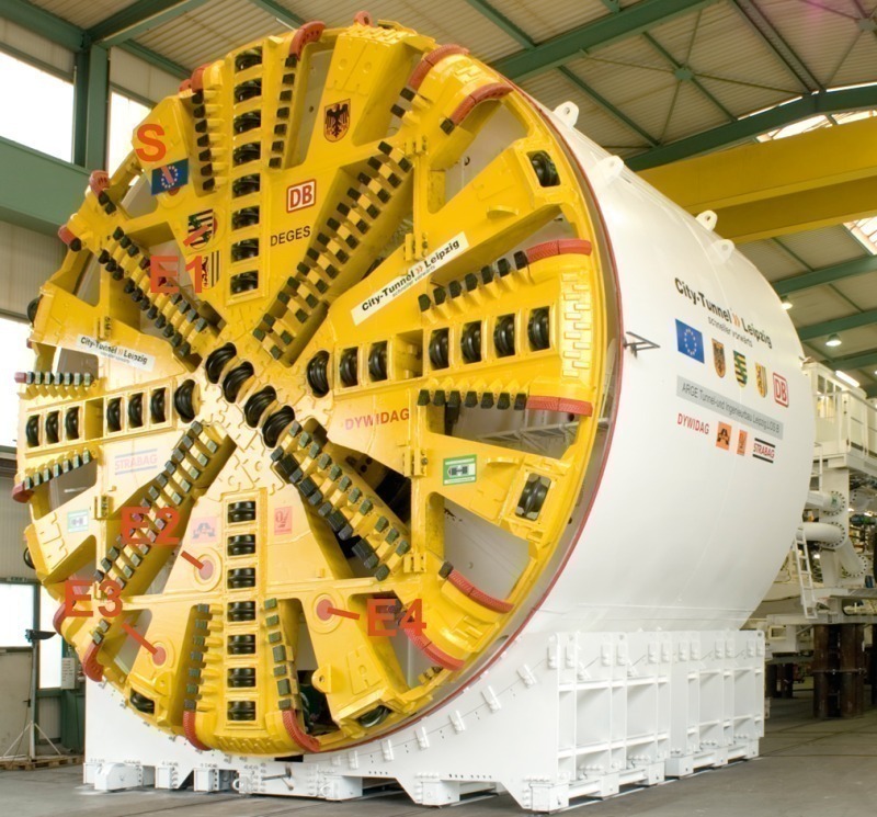
the more significant, to assure the straightforward integration and reliable functioning of this specialised high tech system in the rough environment of a TBM. The latest system im-provements were incorporated in the Herrenknecht Mixshield (9.00 m diameter) for the Leip-zig City Tunnel (D), which tunnelled through the subsoil in downtown Leipzig from January 2007 till October 2008.
1 SSP – Principle and Method of Functioning
The SSP method is a non-destructive seismic advance exploration method for mechanised tunnelling with slurry-supported face in soft ground. It is marketed and further developed by Herrenknecht AG in conjunction with the Mixshields produced by the company. Of all comparable geophysical exploration systems devised so far, the SSP system possesses a high degree of integration in a TBM and is designed specially for the continuous monitoring of the soft ground formation in front of the tunnel face without negatively affecting the excavation. In other words, the SSP process runs parallel to the process of boring.
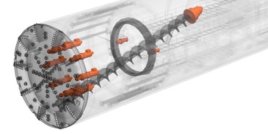
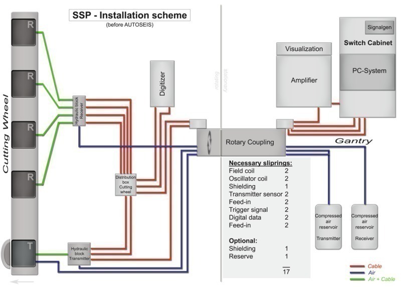
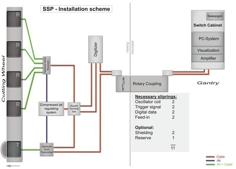
The transmitting and receiving units necessary for advance exploration are directly integrated in the tunnel boring machine’s cutting wheel (Fig. 1). The complicated sequence of data processing, analysing the results and visualisation was automated as far as possible and takes place practically in real time (duration roughly 3 to 5 h after a measurement cycle is concluded) in the back-up zone of the tunnelling machine.
The measurement method is based on acoustic reflection measurement according to the correlation location principle. Correlation locating methods are especially suitable for use in environments with very high noise levels. Petrophysical contrasts produce reflections when the ground is scanned by sound. The determining physical magnitude here is the seismic impedance (also: acoustic resistance or wave resistance) Z, which results as a product of the density r of the medium scanned by sound and the seismic (compression wave-) speed n of the emitted acoustic wave in the affected body of soil (Equation 1).
Z = r · n (Eq. 1)
If the impedance alters abruptly, i.e. a sufficiently large impedance contrast exists on the interface between 2 media Z1 and Z2 – as for example were to be expected given a clearly defined change of geology – a part of the incident wave is reflected. The strength of this reflection results from the vertical occurrence of the wave on the interface on the basis of the reflection coefficient ar from equation 2:
(Z1 – Z2)2
---------------- = ar (Eq. 2)
(Z1 + Z2)2
The specially coded acoustic transmission signal is emitted directly via the SSP transmitter from the cutting wheel via the support medium (bentonite) in front of the face into the sub-soil with the drive in progress. The propagation speed of the signals is emitted as a so-called up-sweep, usually with afrequency range of 600 to 2,400 Hz.
The effectiveness of the SSP system is largely governed in its range and resolution by the physical processes of the spherical propagation of the signal energy as well as absorption and scattering as well as by data coverage, position and geometry of the reflecting interfaces/bodies, soil heterogeneity and background noises.
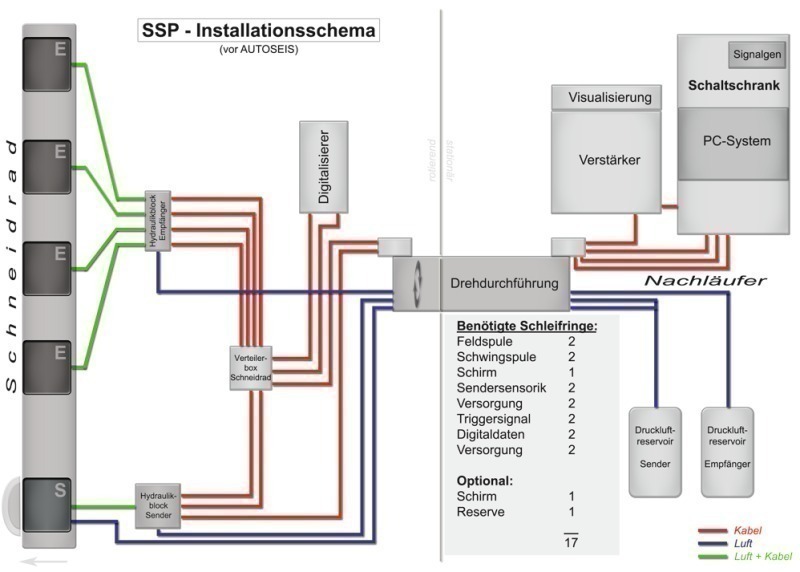
Several acoustic receivers (2 at least), set at certain distances from the transmitter and placed at different radii in the front of the cutting wheel if possible, record the signal reflected by the interfaces, which is immediately transmitted in digital form to the processing system in the TBM’s back-up zone (corresponds to the PC system in the control cabinet shown in Figs. 2 + 3). There the registered data record is provided with the corresponding measurement geometry and passes through an automated data processing procedure, which consists of a large number of highly modern seismic processing modules in order to extract the actual reflection signal from the parasitic oscillations caused by the process of boring. All the information gained from a continuous measurement cycle is presented to the TBM personnel on a monitor to be interpreted in a corresponding visualised manner.
In practical use exploration ranges of more than 40 m were attained with the resolution capacity varying over this distance and diminishing as the distance increases. Generally only obstacles can be identified whose dimensions are larger than the smallest wave length l (c = wave propagation speed; f = frequency) of the transmission signal; in the most favourable case at close range (up to 20 m in front of the face) objects in excess of roughly 1 m in size can be detected.
2 Further Developments
Within the scope of the AUTOSEIS project (research project: 03G0638A) lasting
3 years sponsored by the Federal Ministry of Education and Research of the Federal Republic of Germany, it was possible to considerably improve important hardware components. Furthermore new software routines were created and implemented. Towards this end the main aspect on the hardware sector was geared towards ensuring an optimal interaction between all components as possible while at the same time minimising the installation requirements and susceptibility to errors so that in the end effect a higher quality of data acquisition could be assured.
2.1 Improving the Hardware
The adapting of sensitive electronics and control technology to the environmental conditions of a TBM place very high demands on the stability and reliability of all hardware components. Defective components in the cutting wheel can only be replaced at high cost and in a time-consuming manner. There was room for improvement in the case of the pneumatic control for pressure compensation of transmitting and receiver membranes, cooling for the sound transmitter, simplifying the transmittance of electric signals via mechanical ring wheels as well as designing the mechanical stability of the cutting wheel components for hard rock type geologies.
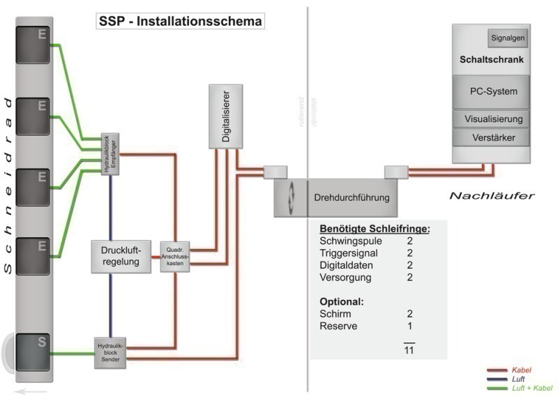
Figs. 2 + 3 display the relevant installation scheme prior to and after further development within the scope of AUTOSEIS. As a consequence of the optimisation described in the following the total installation was reduced to the components shown in Fig. 3. Even at first glance it is evident that the installation requirement especially in the field of compressed air supply (blue) as well as the electric lines (red) has become considerably easier, which means of course that a reduction of potential sources of error, less working time and lower costs are associated too. In the rotating part air channels from the TBM’s rotary joint as well as at least 6 ring wheels are eliminated. Furthermore the compressed air reservoir for transmitter and receivers so far housed in the back-up system could be eliminated. The amplifier, which strengthens the sound signal generated by the signal generator and passes it on to the SSP receiver, was replaced by a substantially more compact unit. Just like the visualisation module it is now permanently installed in the SSP control cabinet so that this now contains all the hardware components required on the backup system.
Pneumatic Control
The transference of energy from the sound source into the subsoil and from the subsoil to the receivers largely depends on the connecting conditions to the transmission medium. The pressure on the face results from the overburden height, the average rock density as well as the groundwater level and greatly determines the necessary supporting pressure in the bentonite suspension. This external pressure must be compensated by air pressure in the transmission and receiver units in order to assure the membranes can oscillate freely.
Prior to the new development of a pneumatic control system the air pressure for the SSP components was provided by means of a complex installation (running via the rotary joint) so that it required a great deal of maintenance and was prone to errors (Fig. 2). The support pressure so far had to be regulated manually thus temporary false adjustments were inevitable.
Nowadays the transmitting and receiving membranes are provided with compressed air via the co-rotating compressed air control in Fig. 3, which corresponds to the support pressure at the level of the machine axis so that all components – relating to the transmitter – are uniformly compensated.
Cooling the Sound Transmitter
The SSP system utilises an electro-dynamic oscillator to generate elastic waves. To generate the required static magnetic field so far a permanently energised field coil served as abutment for the moving coil, which is produced by the specially coded signal form for the elastic wave.
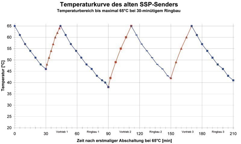
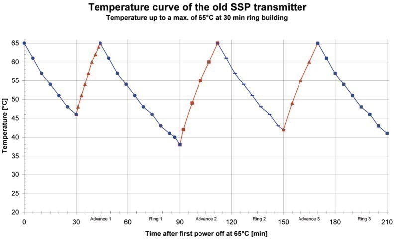
Heat, which has to be removed to avoid the coils sustaining damage, is produced to a not inconsiderable extent on account of the soil resistances. The compressed air to assure the central position of the transmitting and receiving membranes was at the same time used as a circuit (Fig. 2) in order to cool the transmitter’s coils. In addition a protective circuit prevented the coils from heating up and in turn the measurement system from total failure. As a result, however, the measurement frequency inevitably diminishes. Fig. 4 shows on the basis of a an example actually measured for a temperature course for the old SSP system for 3 driving and ring installation cycles, with each cycle assumed in the ideal case to take 2 x 30 min. It is evident that the heating up phases until the critical temperature of 65 °C (red curve sections) is reached, in which data could be acquired, only accounted for 2/3rd of a driving cycle. The cooling down phases during ring construction (blue curve sections) did not suffice to cool down the coils sufficiently so that measuring could take place completely throughout the next drive.
As the quality of the final results largely depends on the continuous data density a more effective cooling system was imperative.
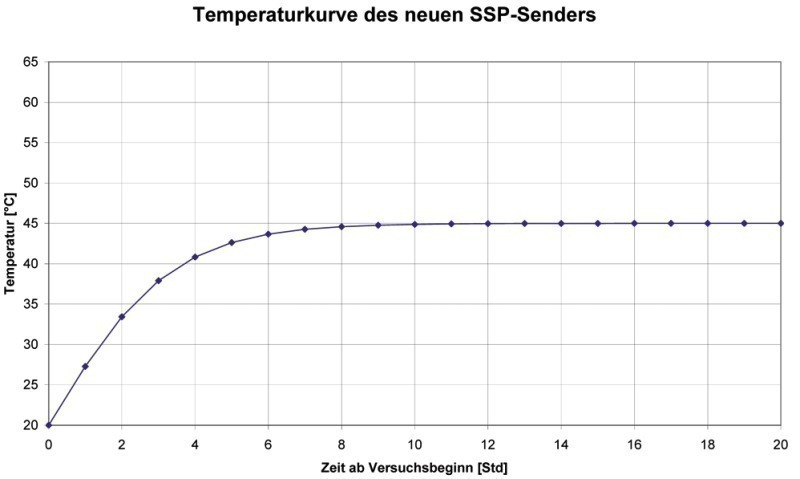
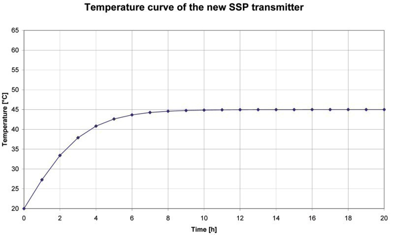
As a result instead of the field coil a permanent magnet was deployed. In this way it turned out to be possible to keep the temperature in the transmitter below the critical temperature so that continuous measurements were possible. The temperature course for the new SSP system is presented in Fig. 5. It is obvious that – even in continuous mode (1 s signal per 10 s) – no higher temperature than 45 °C is produced in the transmitter casing.
In addition to the improved data quality thanks to continuous measurements there is a clear reduction of possibilities influencing errors during the commissioning and operation of the system thanks to the elimination of the cooling circuit and becoming independent of the rotary joint.
Improving the Transference of Signals from the Cutting Wheel
The mechanical transference of electric power to the cutting wheel and digitalised data from the cutting wheel by means of ring wheels represents a technically susceptible hardware component. As a result the concept foresaw reducing the number of mechanical ring wheels as far as possible. This was accomplished by eliminating the field coil for the SSP transmitter and the corresponding sensorics. Through the application of WLAN transmission further ring wheels are to be saved in future as well.
Assuring Operational Safety for Geology with high Proportions of Solid Rock
The systems applied for far were operated exclusively in soft ground soils with bentonite-supported face. However a pure soft ground environment seldom exists. Experience has shown that slurry-supported TBMs are also applied in heterogeneous geologies thus for instance there was a relatively high proportion of solid rock in Leipzig. As a consequence the hardware components were further developed in such a way that they are also capable of functioning in geologies with direct contact between the cutting wheel surface and the material being extracted. Towards this end a mechanical stop was developed so that components were not destroyed when there was direct contact with solid rock.
2.2 Development of Software
Thanks to the development steps described in the following the data quality and in turn the interpretation capabilities of the SSP method could be improved decisively.
Development of Algorithms for a 3D Speed Analysis
Changes in geology, water saturation, porosity or rock stress accompany changes in the propagation speeds of elastic waves. For example depending on the mentioned parameters, dry sands can record compression wave speeds of 0.2 – 1.9 km/s, moist sands 1.5 – 2.0 km/s and sedimentary rocks such as sandstone or limestone 1.5 – 5.5 km/s. For comparison; concrete generally lies between 3.5 and 4.2 km/s. The recorded seismic time series mainly serve to obtain a spatial structural image of the subsoil. For this purpose the speed field must essentially be known, for the holographic principle is applied for depicting the reflected wave energy on a given reflection point: the wave fields, which are emitted by the transmitter and those, which are registered by the sensors, are superimposed and in this way generate an image of the reflection points. Within the framework of seismic data processing this process takes place on the computer (PC system in Figs. 2+3). Only knowledge of the propagation speeds enables the wave fields to be superimposed correctly in this case. Faulty speed fields lead to considerable blurs. Thus knowledge of the 3D distribution of these speeds in heterogeneous soil is necessary for assessing the rock geotechnically.
Determining the 3-dimensional spatial distribution of the wave speeds of the propagation medium is described as 3D speed analysis within reflection-seismic data processing. The conventional algorithms as e.g. used in the oil industry cannot be applied for the measurement geometry associated with TBMs. The demands relating to detecting small-scale fluctuations or when dealing with noisy data are particularly great in tunnelling. Consequently a new algorithm was developed within the scope of this research project on the principle of consistent imaging. This states that a reflector when scanned from different positions is only depicted in each case at the same spatial position providing that the speed field relating to the image is correct.
Development of Algorithms for aligning Amplitudes
A correct computational adjustment of wave propagation losses represents an important prerequisite for enhancing the interpretation safety. If it is not possible to align amplitudes with sufficient accuracy, then in the case of the migration of time series method, given a known wave speed, the measured time points allocate the seismic signals to their point of origin – leading to anomalies in the presentation cube (detected reflectors), whose position can be certain but whose absolute value is defective regarding the resulting reflectivity distribution. As a result it is not possible to compare the anomalies and determine their cause.
A fundamental system analysis revealed the most important factors of influence, which are to be taken into account within the imaging process. These were continuously updated and embraced the application of theoretical statements on the SSP system taking particular consideration of the signal-to-noise ratio and signal compression. The corresponding algorithms were worked out with current SSP data from Leipzig and illustrate the system’s theoretical analysis. The test to check and refine the algorithms took place both on model test data as well as on SSP original data. After successfully testing the migration algorithm, independent evaluation software was created, which can be applied parallel to the system currently used. In this way the influence of the driving parameters of the TBM (contact pressure, rate of advance, rotation speed and cutting wheel direction of rotation, differences in pressure between the transmitting and receiving membranes) was examined to determine forms of signals, energy and information content (genuine amplitudes) and incorporated in the evaluation algorithms for calculating the visualisation cube.
3 Results
Through meticulous analysis and reprocessing the seismic data acquired in Leipzig further optimisation steps were arrived at, which can find direct application in future projects together with the further developments previously described. In this connection for the first time a close correlation between seismic reflectivity and machine reactions (especially torque and tilting moments of the cutting wheel) were systematically established. Checking the SSP results took place on the basis of the TBM rates of advance and the amount of spoil registered.
For the Leipzig City Tunnel it was possible to establish artificial obstacles (e.g. sealing blocks, drilled pile walls, diaphragm walls of former construction pits, headings for retrieving anchors as well as collector shafts outside the tunnel route) as well as changes in geology (sandstone and quartzite banks).
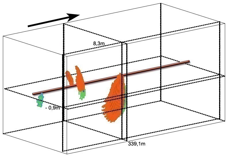
In the following a number of instructive examples will be provided to show the current performance capability. The result to be interpreted on the spot of the geophysical working process is a 3D image of the reflection elements occurring in a cuboid, defined area (10 x 10 x 40 m) in front of the tunnel boring machine, represented by the backscattered amount of energy (Fig. 6). Orange and green reflection elements are presented, which correspond to high positive or negative amplitude of the reflectivity and thus indicate an impedance contrast, as previously described.
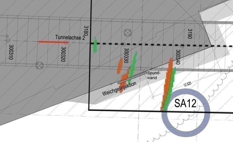
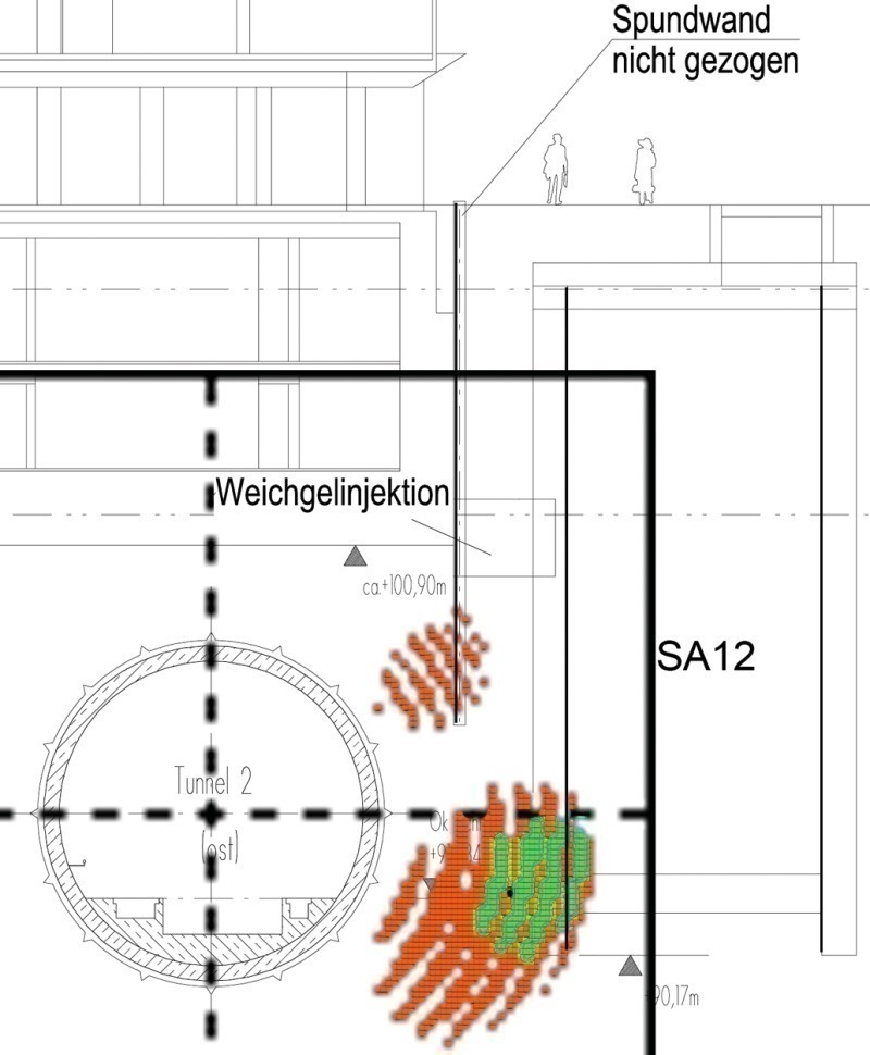
In order to present the examples as lucidly as possible the corresponding 2D sections were selected from the given 3D cubes and placed on the existing geotechnical cross-sections with the aid of graphic processing software. In this way a direct reference between the reflector and the object can be established. Fig. 7 now shows a top view of the situation of a pile wall not withdrawn at TM 300330 and the unfilled shaft SA12 at TM 300338 outside the route. The red line in all examples marks the area, from which the data for the given result have been obtained; the black frame stems from the visualisation software. If the fact is taken into account that the lateral resolution of the SSP results is considerably more unfavourable for geometrical reasons, particularly outside the tunnel cross-section, than the resolution along the tunnel axis, then the location and amplitude of the reflectors mirror the position and nature of the artificial objects remarkably well.
This is also evident in Fig. 8, where the reflectors are also to be found at the proper place looking towards the drive. A further effect is also recognisable here, which impressively shows the nature of wave propagation. As the undrawn pile wall, which is almost completely reflected by the sound energy, lies in front of the shaft but is not so deeply installed, a shadow zone is created behind the pile wall. As a result the shaft SA12 is only displayed in the lower section.
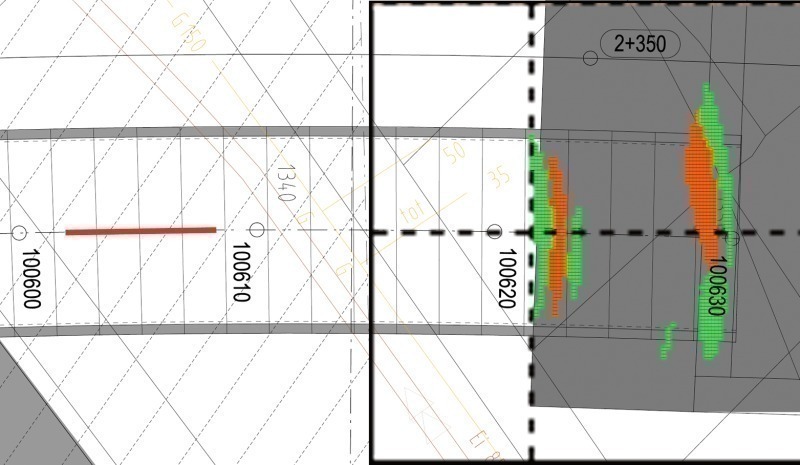
The example in Fig. 9 indicates the detection of a sealing block in the correct position. Both the front edge area (intersection soil to concrete) as well as the rear edge at roughly 100630 (intersection concrete to air) are outstandingly depicted.
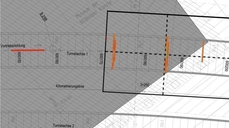
Construction site reports and machine data indicated that major sandstone intrusions and boulders were extracted mainly between TM 600185 and 600200. The strong reflector in Fig. 10 at approx. 600186 matches extremely well with the front edge of this encountered change in geology. As is shown by the red line the data for this cube stem from the area 600148 to 600156. In other words the SSP result and in turn the advance warning in this case lay some 25 to 30 m prior to reaching the sandstone bank, taking the processing time into consideration.
4 Advantages for mechanised Tunnelling and Outlook
All development and optimisation steps on the hardware and software sectors directly result in a noticeably higher quality standard for the SSP system. The quantity and quality of the acquired data were decisively improved. The direct consequence of better seismic raw data is a preciser location accuracy for identifying potential disturbing objects. Thus the SSP can serve as a very useful warning system, which provides the construction site personnel additional information about the subsoil quickly and reliable during the drive, thus precluding unpleasant surprises.
This includes the early tracing of unexpected obstacles in the boring track as well the verification of known objects. As a result this instrument greatly contributes towards enhancing safety in tunnelling.
There is always the possibility to undertake more involved analyses with the aid of the SSP results also after driving a section. Thanks to continuous data evaluations and correlations with existing geological and geotechnical information as well as recorded machine data and spoil classifications invaluable recognitions can be obtained and the accuracy of forecasts for future sections of tunnel considerably improved in the course of time.
The now substantially leaner system requires less production, installation and maintenance effort and is less prone to error, something which is reflected directly in a lower price for the SSP system and in turn a better cost-benefit ratio.
5 Outlook
The achieved developments reflect more than 10 years’ experience with the SSP advance exploration system. It has been revealed that the integration of the SSP data in an existing data management system can considerably contribute to quality assurance in mechanised tunnelling providing that systema-
tic analyses of the SSP results with the aid of further additional information – such as geology, geotechnics and TBM data – are undertaken. Through the application of the SSP advance exploration system risks during the excavation process can be minimised and rates of advance, for instance with regard to an adapted mode of operation by the shield operator, optimised.
Future developments will e.g. centre on adapting the SSP system to EPB shields (earth pressure balance). The installation of SSP into this type of machine admittedly differs little in technical terms but the conditioning foam frequently applied in the case of the EPB prevents the decoupling of sound energy in the soil so that according to the current level of technology exploitable data are only then available when no foam is being injected.