Liefkenshoek Railway Tunnel in Antwerp
The currently biggest infrastructural project in Belgium is forging ahead in the form of a Public Private Partnership (PPP) in the bounds of the Port of Antwerp: Undercrossing the Schelde and the Canal Dock. In 2013 the new tunnel for freight trains will connect the left bank of the River Schelde with the right one.
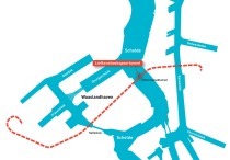
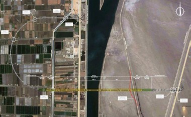
On account of the intensive use of the Port of Antwerp/B, especially on the left bank of the River Schelde where 7.5 mill. containers are handled each year, a considerable increase in goods transportation by train is anticipated. The main railway hub is located on the right bank (Antwerp North). As soon as the new tidal dock is completed, up to 100 goods trains/day will travel between the two river banks. Fig. 1 provides a schematic overview of the port facilities. The link will enable trains to travel back and forth without having to leave the port area. In addition operating costs for the trains will be lower as the railway route between the larger locations on both banks will be reduced by roughly 22 km.
During the planning phase the road tunnel below the Schelde – an immersed tunnel – had to be taken into consideration. It was built in the 1980s and is located close to the new tunnel route. Furthermore restrictions relating to gradients for railway tracks had to be observed, which are considerably flatter than those for roads. The “Liefkenshoek Rail Link Project” (LHSV) is one of the biggest infrastructural projects ever to be embarked on in Belgium. It takes the form of a Public Private Partnership (PPP) project running for 38 years. This roughly 16.2 km long infrastructural project for railway freight traffic, which connects the southern part of the port (left bank) with railway line 11 in Antwerp’s northern port (right bank) has to undertunnel the River Schel-de and the B1-B2 Canal Dock.
Project Description
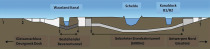
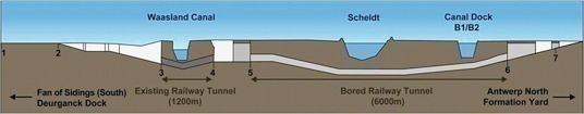
The building of the project was laid down in a so-called DBFM (Design, Build, Finance and Maintenance) contract valued at around 680 mill. euros. Two single-track tunnels roughly 5,970 m long to be created by shield driving and an internal diameter of 7.3 m as well as several km of tunnels by cut-and-cover with deep diaphragm walls and cement-bentonite walls have to be produced. The total project is divided into 13 construction sections (KW) including an aqueduct, the renovation of the existing, 30 year old Beveren Tunnel (which has never been used), the starting shaft, 2 TBM tunnels with cross-passages (CP) and evacuation shafts (ES) as well as the end ramp (Fig. 2). Execution of the project began in November 2008 with the setting up of the construction site installations on various sites. The critical part is the building of the starting shaft, as both TBMs depend on this to remain in their time frame. TBM No. 1 starts the excavation in January 2010, the second TBM 2 months later in March 2010. Work has to be finished in July 2013.
Geology and Hydrogeology
The geology along the route consists of fill, quaternary sands (alluvium), several layers of tertiary sand with various formations (Kattendijk, Merksem, Berchem, Lilo, Kruisschans) with low proportions of clay and glauconite as well as Boomse Klei, a stiff, overconsolidated and fissured tertiary clay, which is located underneath in the form of a sealing layer (Fig. 3). By and large the tunnel route is located in tertiary sands; however, the clay only ranges upwards to a maximum of 40 % of the tunnel cross-section.
Special attention must be accorded the riverbed of the Schelde with its silt deposits and thick layers of faulty sedimentary soil as well as the Canal Dock, where silt deposits have also to be lent consideration. In the Canal Dock the silt is to be replaced by sand at the behest of the client.
In the course of the project a free groundwater level above the so-called “Polderkies” (clay) in the quaternary sands and 2 artesian groundwater levels above the Boomse Klei have to be taken into account, split up by Kruisschans sands, which are interstratified by clay lentils. Furthermore the water levels along the banks of the Schelde are greatly dependent on the Schelde’s tides at the land side, which fluctuate between +8.5 m TAW (Tweede Alge-meene Wateranpassing) and–1.0 m TAW. Depending on the distance from the Schelde a delay in the rise or fall of the water level must be considered.
Tendering Phase, Negotiations and Contract
Prior to issuing the tender for this giant project the client took numerous alternatives into account. In 2006 the tendering documents for Belgium’s largest ever infrastructural project, with the Infrabel N.V. as client, were offered to a restricted number of pre-qualified consortia. The tendering documents included a fundamental reference design provided by the client’s technical consultant (Tuc Rail Engi-neering), a strict catalogue of requirements with a number of special demands, project-specific descriptions. A complete set of soil appraisals and a so-called evaluation matrix with questions to be responded to by the bidder were issued. The replies to these questions were assessed by the client and converted into a point rating system. Following several tendering phases the DBFM contract was awarded to the successful bidding consortium LocoRail NV in November 2008. It consists of the Belgium company CFE NV, the French VINCI Concession SA company and the Dutch company BAM PPP as project company.
The construction consortium, THV LocoBouw, consisting of MBG/CFE, CEI-de Meyer, Vinci Construction Grand Projets and Wayss & Freytag Ingenieurbau AG, were commissioned to build the project by LocoRail NV. Within the consortium MBG and CEI-de Meyer are responsible for the construction work. Vinci and Wayss & Freytag, French and German tunnelling specialists, are in charge of the shield drives to produce the tunnels and cross-passages with Vinci responsible for the technical management.
KW 10 – Shield Drives with Cross-Passages
In the following the section KW 10 is discussed, which comprises 2 tunnels to be produced by shield driving, which are approx. 5,972 and 5,980 m long. The tunnel lining is 0.4 m thick. The minimum curved radius amounts to 1,500 m. The tunnel drive has a maximum 1.25 % gradient. The minimum soil overburden along the tunnel route amounts to some 3 m in the Canal Dock area, something that calls for special measures. The maximum overburden equals roughly 33.6 m and the maximum water column above the tunnel floor is about 40 m.
Along the tunnel there are 13 cross-passages and 8 connections with evacuation shafts to be produced. Generally speaking the cross-passages and evacuation shafts are built alternately at approx. 300 m gaps. Beneath the River Schelde 5 cross-passages at gaps of roughly 250 m without any evacuation shafts located between them have to be produced. The tunnel drives start in the access shaft near the port of Waasland. The target shaft for both TBMs is located on the right bank of the Canal Dock.
TBMs, Separation Plant and Segments
The shield tunnels are driven by 2 mix-shield TBMs made by Herrenknecht. Each TBM is approx. 8.4 m in diameter and has a conic tail skin. The tunnelling installation including 5 trailers is about 110 m long. Both TBMs are fitted with an electric drive with an installed thrusting force of roughly 60,000 kN. The operating pressure of the TBMs amounts to 4 bar. The TBMs are equipped with a closed cutting wheel, which rotates in front of the shield. The TBMs and the tunnelling installations were designed by Herrenknecht in close collaboration with specialists from both construction companies (Fig. 4).
The preparation of the supporting fluid and the slurry management is carried out with a separation plant from the French manufacturer MS France, which was awarded the contract for supplying it. On account of the special properties of Antwerp sand a number of tests were undertaken with soil samples when designing the separation plant. The separated sand is reutilised for fills at other locations throughout the project.
The tunnel rings constitute 8 precast elements with an arched length of approx. 3.5 m and are 1.8 m wide. A conic keystone closes the ring. The segments have to be produced in C50/60, XF2 concrete quality with an inner concrete covering of at least 40 mm.
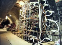
As far as designing the standard reinforcement cages for the segments is concerned, emphasis was placed on the fact that 53,000 segments (Fig. 5) are to be produced. Consequently a cage suitable for mass production was devised in conjunction with the concrete segment supplier, the German company Max Bögl Fertigteilwerke GmbH & Co. KG. Special rings with a greater quantity of reinforcement are to be installed at the cross-passages and the connections to the evacuation shafts. The cross-passages are to be produced protected by ground freezing. In accordance with the client’s catalogue of requirements the tunnel lining must be able to sustain a fire load in keeping with the RWS fire curve. Thus the client demanded that 3 kg/m³ of PP fibres was to be added to the concrete mix, which was to be produced with limestone aggregates. In addition additional fire protection has to be installed on the inner surface of the tunnel. The appropriate fire protection had to be tested by means of a large-scale fire test involving the affected concrete precast elements. The test series executed at the MFPA Leipzig with various amounts and 2 types of PP fibres revealed the positive effect of PP fibres. On the basis of the results, which were also attained with 2 kg/m³, LocoBouw and LocoRail suggested to the client that the quantity of fibre should be reduced, which meant the concrete could be more easily processed. Production of the segments started in May 2009 at the Max Bögl factory in Ham-minkeln/D.
Underpassing the Schelde and the Canal Dock
The TBMs have to pass below the River Schelde with extremely shallow overburden. The bulk of the overburden consists of faulty tertiary sands with unfavourable soil properties and a specific weight of only 14 kN/m³. In keeping with the soil investigation carried out by the client a layer of silt was expected above the faulty tertiary sands. The thickness of the layer was not exactly known. Loco-Bouw decided to undertake a high resolution seismic measurement in the Schelde to determine the silt’s thickness. The results indicate a very thin layer of silt and confirm the thickness of the faulty tertiary sands as predicted in the client’s investigation. The layer of faulty sands obviously does not run with the expected gradient, something which should have been registered when the Liefkenshoek Road Tunnel was immersed.
Furthermore the River Schelde’s water level can vary with the tides by 9.5 m between high and low water level, something that has to be considered when installing the supporting pressure unit for the TBMs.
As the soil overburden above the tunnel is very shallow, the minimum supporting pressure of the bentonite suspension at the face practically equals the maximum supporting pressure. It has been established that compressed air accesses at the deepest point on the river bed are not possible. As a result the cutting wheels of both TBMs are to be inspected during a break for maintenance prior to passing this very critical section. The critical phase of the project is driving the two tunnels beneath the Canal Dock on account of the extremely shallow overburden of merely 1.1 m in conjunction with the client’s demand that the Canal Dock must be kept free for large ships. A certain water level has to be maintained in the Canal Dock at all times throughout the construction period. The gradient of the railway tracks was made as steep as possible in order to ensure the tunnels were as deep as possible. As the present soil in the Canal Dock consists of a layer of silt, which extends down at the most to the tunnel axis, the client requested the silt be replaced by compacted sand prior to the TBM passage. In order to reduce the amount of compacted sand the client suggested that a 2 m thick concrete slab should be produced above the tunnel as anchorage and to provide additional weight so that the TBM passage was facilitated.
During the planning of execution LocoBouw presented an alternative design for replacing the soil combined with a 2 m thick reinforced concrete slab so that the temporary fill could be reduced to a minimum and increase the level of safety during the TBM passage. LocoBouw will produce a roughly 250 m long and 35 m wide pile wall excavation pit, in which the silt is replaced by a low-strength mortar (Fig. 6). The mortar is to be covered by a 2 m thick reinforced concrete slab. A local temporary fill will be carried out in the proximity of the slope. Thanks to the mortar higher stability beneath the slab is to be attained than is possible with compacted sand.