Steering Supporting Measures for Urban Tunnelling
The improvement of urban infrastructure, particularly the building of efficient and attractive links for public commuter transportation, can often only be achieved by means of tunnels in view of the amount of space available. Towards this end analytical forecasts on the quantity of effects expected during construction are frequently stretched to their limits. The following report shows how intelligent and adaptive supporting and compensation measures provide help in this respect in keeping with the observation method principle.
Frequently sensitive buildings are located within the sphere of influence of tunnels, which have to be correspondingly secured against irreconcilable effects. The inter-actions between the existing building, intervention in constructive technical terms, subsurface and groundwater are extremely complex in this connection so that analytical forecasts pertaining to the quantity of the anticipated effects are stretched to their limits. As a result intelligent and adaptive supporting and compensation measures in keeping with the observation method principle are all the more important. Towards this end a distinction has to be drawn between process-integrated and autonomous supporting measures.
Autonomous supporting measures permit expected effects or those that have already occurred to be compensated for. Process-integrated supporting measures prevent irreconcilable effects occurring to the affected buildings during the drive in the first place. Both approaches do not preclude each other, far rather they are complementary and can be applied parallel to each other if need be.
Process-integrated Supporting Measures
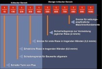
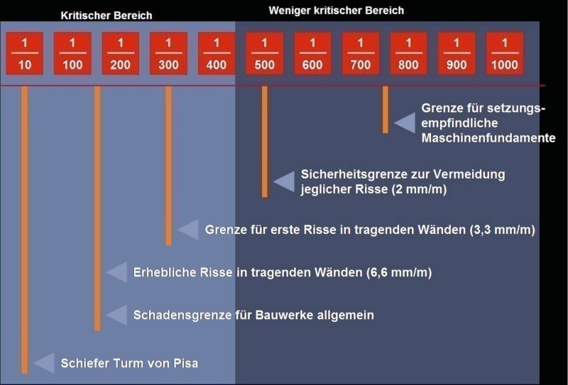
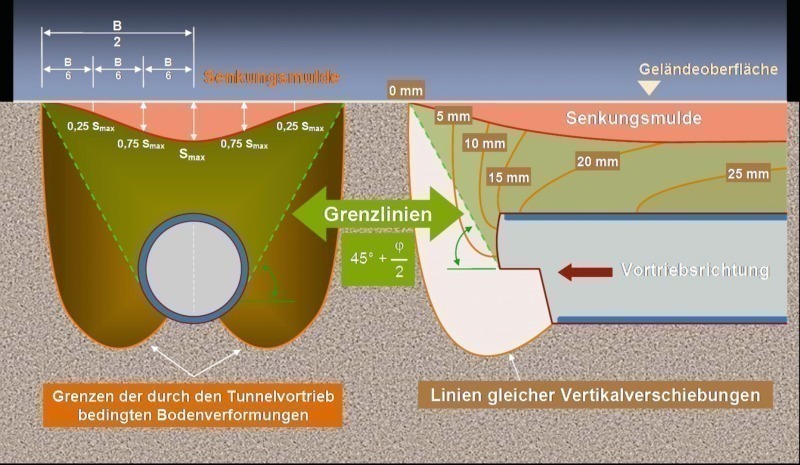
Process-integrated supporting measures are designed to prevent irreconcilable effects occurring to buildings and structural parts. This means it is essential that as an integral part of a steering circuit they are already bound in the tunnel driving process or its steering. The prerequisite is that controlled variables exist which can be well steered, upon which influence can be exerted on the effects (e.g. settlements, settlement differences, tilting, water levels, earth pressures, coercive forces) for buildings and structural parts (Fig. 1).
For a mechanised tunnel drive, the following controlled variables are for instance available:
■ TBM rate of advance
■ Face supporting pressure
■ Grouting pressure in the annular gap of the segments
■ Grouting quantity in the annular gap of the segments.
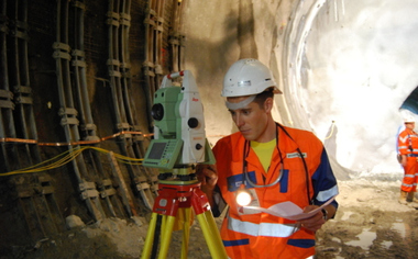
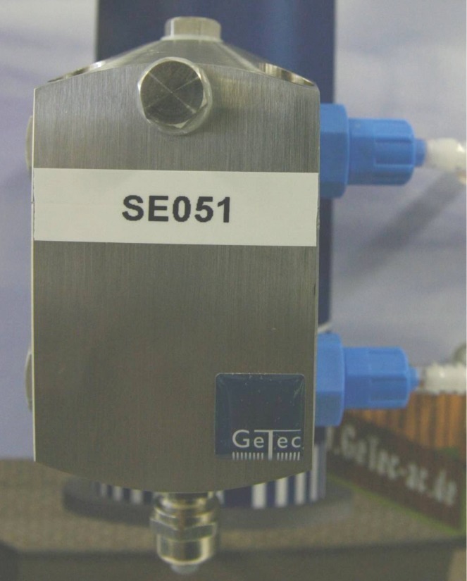
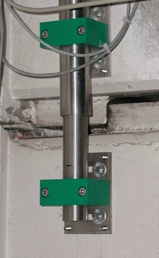
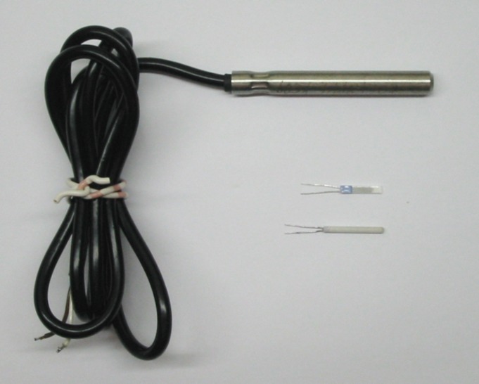
Steering these variables must be undertaken based on measured variables, which have to be collated in keeping with continuous process control from a real time measurement system and evaluated and visualised in lucid form. These real time measurement systems can be accomplished nowadays as multi- channel measurement systems, which with a practically random number of varied kinds of sensors can collate a large number of different measured variables on a permanent basis (Fig. 2):
■ water level gauge measurement systems (settlements)
■ inclinometers (tilting)
■ displacement transducers (crack widths)
■ strain transducers (structural part stresses)
■ load cells and pressure pads (e.g. anchor forces)
■ measurement anchors (course of stress in subsurface)
■ pore water pressure sensors and water pressure sensors
■ total stress sensors (earth pressure)
■ extensometers (compression and elongation in subsurface)
■ horizontal and vertical inclinometers (transversal deformations).
For our engineering interpretation of the interactions the measured and controlled variables must be stored, evaluated and visualised with a suitable software system if only on account of the huge amount of data that accumulates. For mechanised tunnel drives the ATDS® (Advanced Tunnel Drive Steering system [10, 12]) is available.
It represents a data bank application, which was devised by the GeTec Ingenieurgesellschaft mbH in collaboration with the Hochtief Construction AG.
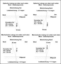
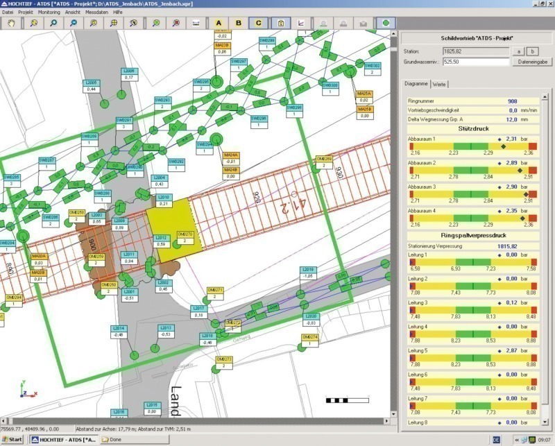
The system is linked to a data bank via an open interface (various data bank systems can be used), in which the measured values of the real time measurement system (e.g. water level gauge [4, 6], measurement values from geodetic systems (total station, levelling unit) as well as the essential driving parameters are stored. All stored values are continuously evaluated and provided in various presentations and process images. The spectrum ranges from the complete overview of the drive by way of the presentation of the current extract for the shield operator (Fig. 3) right up to detailed presentations and time variation curves for individual measurement values. In this connection maps, images and plans can be provided, which facilitate orientation within the project and the allocation of measured and controlled variables to sensors or affected buildings. For visualisation purposes an automatic 3D-CAD core is used. This CAD core permits a 3D underground model for the entire project to be set up, in which the geological and hydrogeological conditions can be taken into account alongside the geometry.
Thanks to its development as a client-server system a number of users can obtain the data at the same time. It is possible to award different access rights. On this basis different presentations and formatted reports can be defined. The construction management, client, tunnel control centre and other involved parties obtain their individually configurated perspective with the data and information relevant for them.
When assessing the overall situation a multistage comparison of all measured and control variable is possible with previously determined limit values in the form of a traffic light control system or diagrams. The alarm system also responds to these predetermined limit values, which provides automatic reports via SMS and/or E-mail to a freely configurable alarm chain. As a result of this automatic alarm system the operating safety of the entire system is considerably enhanced. At the same time the operating modes for the measurement system are monitored and included in the alarm process.
Autonomous Supporting Measures
Should suitable control variable be lacking in the selected driving technology, then these are not steerable to a sufficient extent or if their effect is inadequate then possibly process-integrated supporting measures may not suffice. In order to prevent irreconcilable effects on buildings in the drive’s sphere of influence a number of controlled variables must be created by means of a constructional measure independent of the drive. In this way influence is exerted on the effects for the buildings constructionally separated from the drive (Fig. 4). Since the 1980s compensation grouting (Soil-frac® [3, 5]) has been an applied autonomous supporting measure. In the case of compensation grouting step-by-step a usually predefined amount of hydraulically hardening suspension is installed in the ground under pressure through a series of sleeve pipes. In the process artificial fissures or cracks (fracs) are produced, which are filled with grout while they are being created.
The systematic and multiple treatment of areas of soil with grout leads in the first phase to adhesion with the building being supported (contact grouting, often known as Phase 1). Thanks to the compacting effect on the soil lying between the hardening layers of solid material and through the solid material itself the soil mechanical properties (strength, stiffness and consistency) are improved. If treatment is continued the outcome is a further increase in stress in the soil and ultimately to extremely precise and locally differentiated steerable lifts, by means of which an expected or already occurring effect in the form of settlements can be compensated. The controlled variables for compensation grouting to attain lifts are:
■ amount of grout
■ grouting pressure.
These have to be compared with various data for qualified execution as in the case of process-integrated supporting:
■ Measurement data from a real time measurement system (basically the same measurement systems as in the case of process-integrated supporting can be used)
■ Driving station
■ Data from drill hole surveying when producing injection drillings
■ Groundwater data.
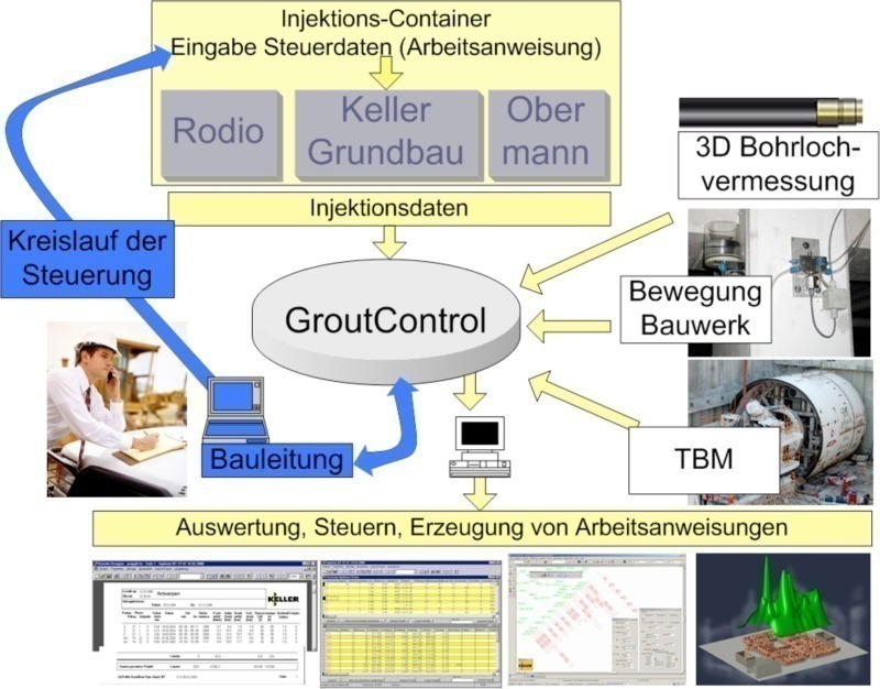
In this case as well huge amounts of data accumulate so that processing supported by software in the form of significant visualisations and reports is required. For this purpose the GeTec Ingenieurgesellschaft mbH also developed the Grout-Control® [2, 8] data bank application. The system was expanded on account of current developments and events so that data relating to the hydrological conditions of a project could also be integrated. Now it is also possible to collate water levels from groundwater measuring stations in real time and pass them on via an interface for analysis using FEM programmes. In addition a so-called real time water manual is in this way available given existing sensorics for flow measurements in water drainage.
The system relies on a SQL data bank system, which is available on the market, via an open interface, stores all previously described measured and controlled variables there and establishes a permanent control circuit (Fig. 5). Forerunners were applied back in 1993 for the first time [1]. The concept has been constantly further developed since that time. Nowadays it possesses a client-server data bank concept. The users communicate with the data bank via a CAD-oriented interface. It can serve as a single unit or is for multiple use and is accordingly freely scalable in accordance with the size and complexity of the project. In this connection the possible amount of data is merely restricted by the applied hardware in terms of storage space, processor capacity and network capacities [3, 4, 7, 11].
For the analysis and visualisation of the data the user enters a data inquiry via a simple to operate mask into the system and receives the results directly in the desired form either prepared as a table, formatted report or graphic visualisation. In addition, the software offers the possibility of producing programme-supported working instructions (in paper form or electronically as input data for steering the injection container). On the basis of the grouting successes already attained, expressed in characteristic values such as e.g. effectivity (grouting quantity per m² per amount of lift in mm) the injection amounts needed to arrive at a specific lift target can be calculated.
The system “learns” together with the engineer during the project from working step to working step with a growing data base with ever greater precision, how the subsurface as well as the building being supported reacts to the installation of the grouted material. These recognitions are certainly invaluable for the project itself quite apart from promoting a profound understanding of the manner in which the geotechnical method functions.
Summary
Today efficient expert systems are available for supporting and compensation measures in conjunction with urban tunnel drives. These systems permit a precise analysis and prognosis of the effects on buildings influenced by the drive in real time through systematic storage, evaluation and engineering presentation of measurement values and controlled variables.
Thanks to real time analysis a degree and precision of steering is attained so that the quality, economy and reliability of process-integrated and autonomous support systems have been enabled to reach a new stage, previously reserved for production and processing in stationary plants belonging to other branches of industry. The safety level of a tunnel drive and the associated auxiliary structures such as e.g. construction pits has thus increased significantly through the application of these intelligent and adaptable steering mechanisms.