4D/5D BIM: Project Controlling for Excavation Support at the Bertoldshofen Tunnel
 Credit/Quelle: Bernd Gebauer Ingenieur GmbH
 Credit/Quelle: Bernd Gebauer Ingenieur GmbH
 Credit/Quelle: Bernd Gebauer Ingenieur GmbH
 Credit/Quelle: Bernd Gebauer Ingenieur GmbH
 Credit/Quelle: Bernd Gebauer Ingenieur GmbH
During construction of the approx. 600 m long Bertoldshofen road tunnel in the Allgäu, Bavaria, the mined tunnel including excavation and support measures was represented using the Building Information Modelling (BIM) method. The work concentrated on the production and linking of a continuous database structure in a defined BIM system environment. In addition to a model in accordance to the tender design, an as-built model was produced parallel to construction based on the digital tunnel documentation. The quantity-based calculation of time (4D) and costs (5D) in accordance with the guidelines in the contract at each stage of the project formed the basis for the monthly payment, performance of precise progress checks and the transparent representation of forecasts.
1 Introduction
In conventional tunnelling, the geology essentially determines the excavation method and support measures used as the tunnel advances. Since the exact ground stratification and geological behaviour are not completely known during the design phase, design and project execution in tunnelling demand flexible structures and tools.
If a design – and thus also a contractual structure – takes into considerations adaptations due to changed information basis, the project can be technically and economically optimised and later conflicts between the project parties can be avoided. Consistent information and its communication are of decisive importance [1]. This requires comprehensive digital networking of people and processes within a project.
The BIM method provides an answer to these complex challenges, In a database with geometrical references, information about construction elements can be provided centrally and analysed by the project parties and used for subsequent applications.
A BIM model of the tunnel can be used through all project phases as a digital information basis, centralised communication tool and for the analysis of variations and their contractual effects. In the course of a pilot project,
the BIM method was implemented during construction of the Bertoldshofen Tunnel for the areas of excavation and support.
2 Project Description
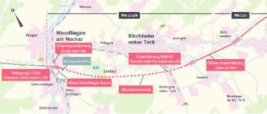
With technical support from the Motorways Directorate of South Bavaria, the State Building Authority Kempten (Allgäu) is implementing the new construction of a bypass round Marktoberdorf and Bertoldshofen on the route of the federal main roads B 16 and B 472, including construction of the Bertoldshofen Tunnel with a length of about 600 m. The planned standard section corresponds to structure gauge profile RQ 11T. The construction works also include a service tunnel about 15 m long, an escape tunnel about 155 m long and an operations building with integrated extinguishing water basin and a bored pile wall for permanent support in the southern starting cut area. At the southern end of the main tunnel a stretch with a widened cross-section was constructed over a length of approx. 30 m in order to ensure stopping visibility for future traffic.
The tunnel was built conventionally using the shotcrete method. The advance support was mostly carried out with spiles and with a pipe screen at the southern end due to the shallow soil cover and adjoining buildings. The tunnel is being excavated in partial faces: first the top heading, followed by the bench and invert. Construction was successfully completed in March 2020. After inner lining and installation of the operational equipment, the tunnel should be opened for traffic in 2022.
2.1 Basics
The BIM project was started at the start of 2019, about two months before the start of tunnelling. The pilot project was commissioned by the client, the Motorways Directorate of South Bavaria, independent of the actual construction works and was intended neither to influence nor basically change the existing design and construction.
The project was implemented according to the general BIM application cases for construction defined as part of the DAUB recommendation for BIM in tunnelling [2] and the guideline BIM4Infra [3]. The essential project aims were the use of BIM for the invoicing of construction works, progress control and structure documentation. Further application cases arose in the course of BIM development and are summarised in section 4.3.
There are not yet any standardised regulations and guidelines for the actual implementation of BIM in tunnelling. The BIM environment was therefore mostly formed with internally developed structures. The BIM project was restricted to the partial model of the outer lining including excavation and support measures. The implementation of the BIM system environment was based on the already completed design for construction of the outer lining. The interface to the construction site was the local site supervision, which was carried out by the engineering office Bernd Gebauer Ingenieur GmbH. Since the implementation of the BIM method required thorough further processing of the information from tunnel driving, it was necessary to involve the tunnel contractor in the development.
2.2 BIM System Instead of BIM Model
The design and invoicing of tunnelling works fundamentally differ from other construction works. The necessary excavation and support measures can often only be decided while tunnelling work is underway based on the prevailing geological conditions. The responsible parties during the construction phase use driving classes defined during the design phase. The use of excavation types and support measures as the tunnel progresses is organised within the planned tunnelling classes like a modular system.
Since the tunnelling measures are dependent on uncertain ground conditions, there is often a lack of precise data for design and construction [1]. In order to be able to grasp the dynamic system of practical construction in the tunnel and holistically represent it throughout the construction project, digital support is to be used, particularly the BIM method.
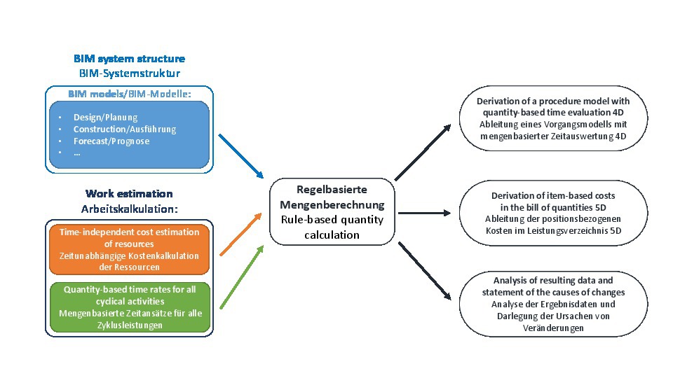
The main focus of the pilot project was the development of a geometry-based database for the conventional tunnel excavation. Eventually, no firmly defined BIM model was conceived for the present project but an inter-model BIM system structure was created, in which all possible design, construction or forecast states of the tunnel drive could be represented. The specified digital data structure enabled systematic coverage of all states in the conventional tunnel drive according to the required modular system. In a next step, the developed BIM system was linked to the contract bill of quantities. For each construction element, the corresponding item quantity could be automatically determined with the resulting data construction time (4D) and costs (5D) using uniformly formulated database queries.
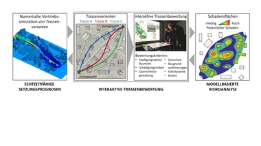
The data resulting from the various information models was analysed and compared with each other. Changes and their causes could be represented continuously to the origin of the information in the BIM model or in the documentation from the site. The concept of the BIM pilot project is summarised in Fig. 1.
3 BIM Model Formation
3.1 Development of the System Environment
The BIM system specifies the structure of the geometries and parameter information to be modelled for each model element. This basic idea demands a continuous information
structure in a flexible and adaptive BIM system environment. Correct formulation of the permissible degrees of freedom in the system ensured the exact representation of individual BIM models in the course of the project. The degrees of freedom thus have to be strictly defined according to the rules in the contract and the design.
The implementation was carried out with the Autodesk Revit software in combination with the visual programming interface Dynamo. The software solution can flexibly represent the geometrical form states of any element through the parameter-supported formulation of dependencies.
The BIM environment was developed with the aim of combining the resulting quantities with the construction contract and making possible immediate evaluations of the construction time (4D) and costs (5D) as the tunnel progressed. The 3D modelling of a construction element was thus only necessary when the quantity calculation of a bill item was based on geometrical parameters. For many components, alphanumeric information about the element in the BIM system was sufficient for the calculation.
With a higher degree of geometrical detail (Level of Geometry), individual models would have been confusing to handle in follow-up applications. In the present case, therefore, a lower degree of geometrical detail combined with flexible parameter-supported data representation was advantageous for the required application aims.
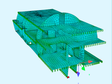
Geometrical Modelling
The rounds in conventional tunnelling were divided into top heading and bench/invert sections. At the Bertoldshofen Tunnel, there was the special feature of a temporary top heading invert arch and a top heading foot widening to increase the support resistance. For precise quantity determination, the following components had to be geometrically represented in the BIM system for each round element:
Excavation volumes
Shotcrete application on the tunnel walls
Area of the face
Area and volume of the top heading invert arch
Volume of the top heading foot
From the modelled geometrical information, the quantities for other bill items such as the reinforcement could also be determined.
In addition to the generally valid invoicing rules of the VOB/C, the tolerances and cambers according to DIN 18312 [4] were important for the definition of the geometrical degree of freedom. Due to the expected ground deformations and constructional requirements, a variable widening of the excavated section has to be taken into account in order to be able to guarantee the required geometry according to the design. Since geometrical changes result from the tolerances and cambers, which are relevant for contractual quantity calculation, these have to be dealt with very precisely and included in the system. Each degree of geometrical freedom can be modified in the BIM system by entering a numerical parameter.
Parameter Table
For other construction elements, it was sufficient to save the quantity-relevant information in the form of attributes. For the parameter structure of the means of tunnelling within a round, internal company standards were developed on the project.
The input of information into a BIM model was carried out strictly according to the system rules in accordance with design and construction contract. For example, installed components could only be added to the system environment if a corresponding item existed in the bill of quantities. This produces a close linking of contract, design and construction and ensures transparency respected by all project parties. In this way, contradictions can be detected early.
3.2 BIM Models
The production of a BIM model entails „filling in“ of the BIM structure for the tunnel drive with alphanumeric information. Predefined input forms are used to automatically create tunnel rounds according to the design rules and the entered information is assigned to the corresponding
construction elements. Essential input data are the geometrical quantities for the location of a round element and its information about the excavation methods and support measures used. The essential difference in the process of producing the individual BIM models is the origin of the information.
Design Model
The design model represents the state of design at the time of tendering. The quantities for excavation and support measures in the BIM model thus correspond to the contract. The production of a design model requires a high degree of detail in the tender design.
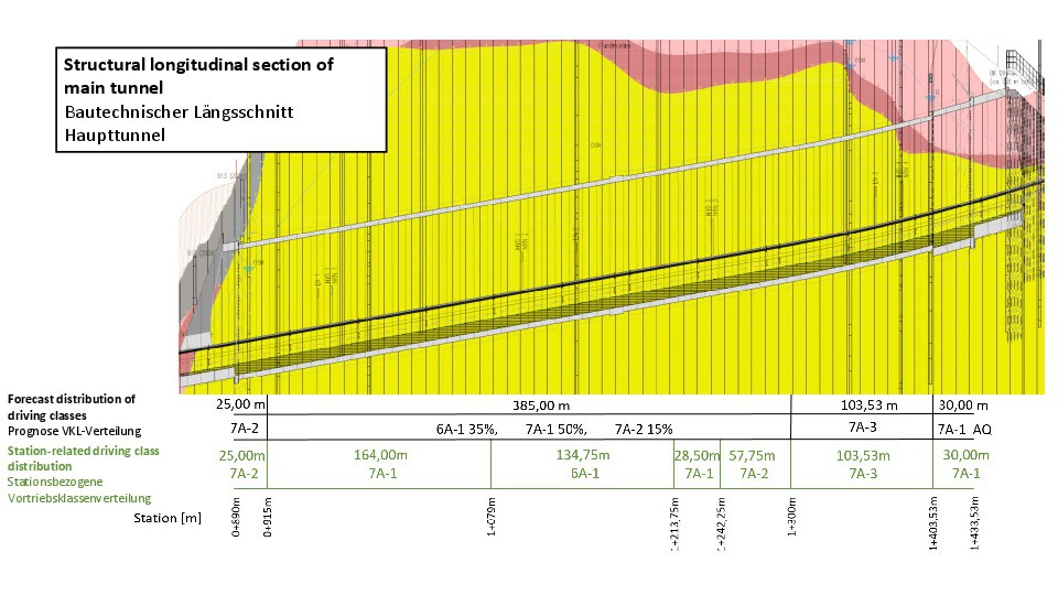
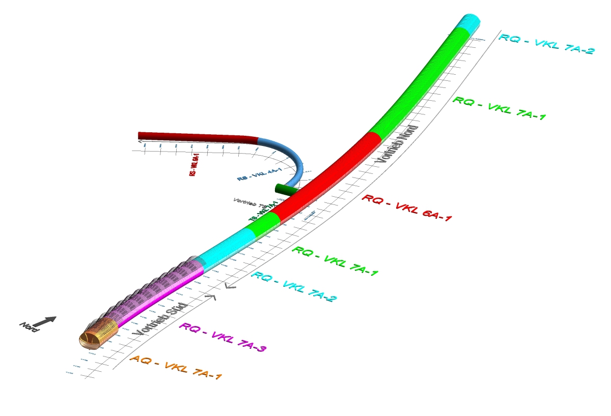
For the planning of the support variants, the geology along the tunnel axis is divided into homogeneous zones characterised according to the geotechnical ground behaviour. Within a homogeneous zone, the required driving classes are estimated in per cent in the usual manner for time and cost planning.
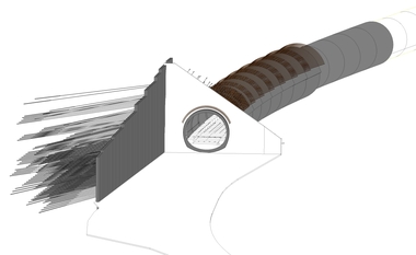
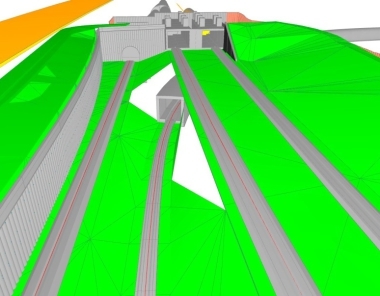
Percentage modelling of the rounds is not generally possible with the BIM method and would not represent any practical construction state, even by an indirect method. For this reason, a station-related driving class distribution was produced in the course of the BIM project in order to thus create a defined implementation in the design model. The proportions estimated in per cent were implemented for this purpose in length components (Fig. 2).
The model is generated automatically based on predefined input forms. The design model resulting from the input values is shown in Fig. 3. Each round contains, in addition to basic information, the forecast tunnelling methods and support measures in a systematic structure at the state of the tender design.
As-Built Model
The as-built model represents the information about the construction process and installed components that were actually used in the course of the construction process. The quantities of excavation and support measures in the BIM model thus represent the basis for invoicing.
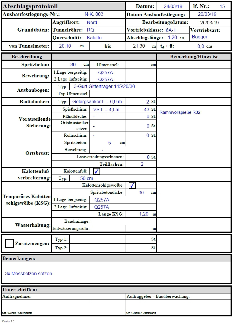
The information from the tunnel is recorded in the form of site documentation. At the start of the BIM project, a digital round protocol was produced with the tunnel contractor for systematic tunnel documentation (Fig. 4). The protocol is the main form of the tunnel drive containing all construction elements and excavation measures.
It delivers all the information necessary to generate the as-built model.
The digital round protocol is, like the BIM system structure, subject to the rules of the design and in the construction contract. Consequently only predefined entries can be made in the protocol on site. If additional
construction elements become necessary in the tunnel, communication and adaptation of the data structure has to be undertaken centrally by the administrators of the project. Further advantages of the system are the constraints clearly defined in advance: the digital documentation avoids potential input errors. The created data follows a strict naming convention. The as-built model is generated automatically based on the digital round protocols.
Forecast Model
Forecasting of time and costs during the construction measure is important for project management and controlling. During the tunnel drive, a forecast model can also be operated in addition to the design model, showing the most probable states of excavation and support measures for the entire tunnel drive. This BIM model is successively updated parallel to the actual construction events. The forecast model thus always represents the most probable state of the completed construction phase under consideration. With automated evaluation of the model database, statements can be made at every time during the project about the expected construction time and the construction costs that will probably accrue.
4 Evaluation
4.1 Automated Quantity Determination
The predefined database structure is linked with the items in the bíll of quantities and evaluated based on rules. The quantities are calculated according to the regulations of the VOB and the rules in the design and the contract. This necessity implies a close interconnection of the design and contractual elements in the BIM model environment.
In the pilot project, the calculation processes of the bill items were exactly predefined based on the BIM system structure. This created a system, which automatically evaluates quantities from each BIM model of the outer lining according to the rules of the bill of quantities and specifications.
4.2 Construction Time for Payment (4D) and Cost Calculation (5D)
The rates of the contractor show the required working time estimated per unit quantity for a time-relevant item. The basic principle of the flexible construction time model is the guarantee that the rates are preserved if the quantities change [5]. The model quantity in combination with the rates give the construction time for payment (4D). Project costs independent of construction time can be calculated from the estimated unit prices (5D).
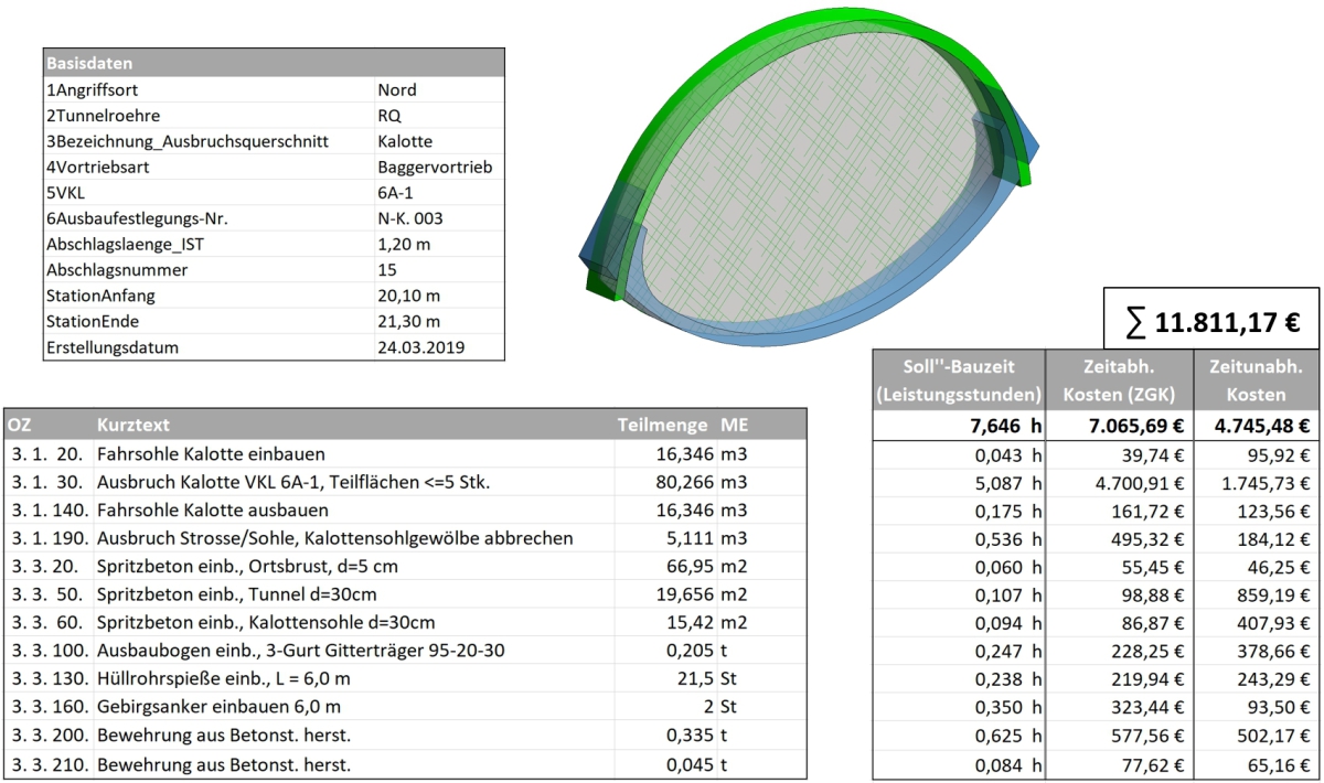
For the round element resulting from Fig. 4, the entire quantity, construction time and cost calculation is shown as an example in Fig. 5. The figures essentially correspond to model-based invoicing. For reasons of data protection, the estimation rates are not taken from the
actual contract with the contractor but are only examples.
4.3 Analysis of the Resulting Data
4D/5D calculation of each construction element of a BIM model produces an extensive information database. The results from the continuous BIM structure can be traced transparently back to the information origin.
With the data resulting from the various BIM models, valuable information could be derived for project controlling during construction of the Bertoldshofen Tunnel. Comparison of two BIM models delivered transparent indications of the cause of changes to construction time and costs (target-actual comparisons).
The opportunities and possibilities of the methods developed for the tunnel drive could be recognised and exploited on the Bertoldshofen project for the following application cases:
Rule-based plausibility checking of the documented tunnelling information
Automated monthly invoicing of items for excavation and support
Improved cost security through better data transparency
Construction progress control against the schedule
Target-actual comparisons and forecasts of quantities, construction time and costs
Systematic data processing and variation checking
As-built model for inner lining, operation and maintenance
5 Experience from the BIM Project
Implementation of the BIM method with the correct degrees of freedom and dependencies for conventional tunnelling demands comprehensive understanding of software, design and practical construction matters and processes. This task can only be dealt with by intensive collaboration between the responsible project engineers and technical specialists.
The use of a continuous BIM system demands rethinking and a new way of working from the project parties. In the pilot project, particular attention was paid to ensuring BIM did not interrupt or change any proven procedures but rather represented a tool for better design and project development. The basis and resulting data in the BIM project were unchanged in terms of content compared to the customary method. This made cooperation and understanding easier for the people involved. Their motivation and acceptance was important for the success of the project since they depend on the user-friendliness of the system interfaces.
From the first monthly invoice to the checking of supplementary claims, the BIM system information was used on the project and the added value for project controlling was noticeable from the start. With positive progress and the new possibilities created with BIM, the interest of the project parties increased greatly. Considering this, the client decided on a follow-up project with model-based support of the inner lining construction. The client side is hoping this will lead to a complete documentation of construction progress, quality and defects management and create a useful instrument for the later operator.
6 Conclusion
The potential of the BIM system can only be fully exploited when it is integrated into the extent of works and services and gains a central position in the project through all phases. Only the collaboration of all project parties in the BIM model guarantees the binding character, correctness and thus usability of the data. In accordance with the “Single Source of Truth” (SSoT) principle, the collected data then forms a central, up-to-date and reliable information basis.
In the construction phase, a central BIM controlling system serves for communication between client, contractor and site supervision as well as for control and monitoring of construction processes. The flexible BIM application system provides precise data under changed constraints and thus enables dynamic design and optimised construction.
In the course of the BIM project, the flexible evaluation and further use of the resulting system data revealed an increasing potential for more application cases – especially for the tunnel contractor. In the BIM project carried out alongside construction, this could not be fully exploited. Thorough use of the method by the client and also the contractor‘s side on subsequent projects could therefore be expected to lead to further application cases in project management and construction practice. Due to the positive experience, the method should be used to a greater extent on future cyclical tunnelling projects.