Continuous Rock Mass Stabilisation on a TBM Drive
Using PUS Foams
 Credit/Quelle: ÖBB [3]
 Credit/Quelle: ARGE Fröschnitzgraben
 Credit/Quelle: ARGE Fröschnitzgraben
 Credit/Quelle: ARGE Fröschnitzgraben
 Credit/Quelle: ARGE Fröschnitzgraben
 Credit/Quelle: ARGE Fröschnitzgraben
 Credit/Quelle: ARGE Fröschnitzgraben
 Credit/Quelle ÖBB
 Credit/Quelle: ARGE Fröschnitzgraben
 Credit/Quelle: ARGE Fröschnitzgraben
 Credit/Quelle: ARGE Fröschnitzgraben
The 27.3 km-long twin-tube Semmering Base Tunnel in Austria has been under construction since 2012. On contract SBT 2.1, a good 8 km of each tube is driven using two shielded hard rock tunnel boring machines. For the sections passing through fault zones, the tender specified foam grouting as tunnelling progresses. This article describes how this foam grouting was dealt with on site – from preliminary trials through the first applications to the method finally used – with an assessment of the experience gained.
1 Project Description
The Semmering Base Tunnel, which has been under construction since 2012, is a rail tunnel with a length of 27.3 km passing under the northern Alpine chain near the Semmering Pass. The two tubes run in parallel at an axial spacing of between 40 and 70 m and are connected to each other with cross passages [1].
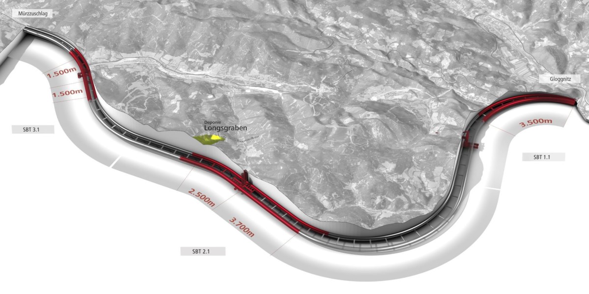
The following information about the project and the tender was taken from various chapters of the construction contract [2]. The entire tunnel is divided into three construction sections (Fig. 1) and is being driven from two portal sites and three intermediate access points:
Tunnel Gloggnitz – SBT 1.1 (incl. intermediate access point at Göstritz)
Tunnel Fröschnitzgraben – SBT 2.1
Tunnel Grautschenhof – SBT 3.1
1.1 Contract SBT 2.1
The tunnel system of this contract comprises the following main elements:
Two single-track running tunnels each about 12.9 km long, driven from the intermediate access point at Fröschnitz. Two-thirds of these two single-track tunnels are being driven using a TBM (tunnel boring machine, 10.14 m in diameter) and about one-third sequentially
Supply and disposal are carried out via two shafts,
400 m-deep, 11- and 8 m-wide (Fröschnitz 1 and Fröschnitz 2), which will be later used as ventilation shafts
26 cross passages at a maximum spacing of 500 m
An underground emergency station
The contract also includes above-ground construction work for the operations, a ventilation building at Fröschnitzgraben and the operation of the Longsgraben landfill site. The following article only describes rock mass stabilisation for the two TBM drives on this contract.
1.2 Tendering of the TBM Drives
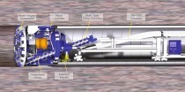
The tender specified two hard rock TBMs of type TBM-S (single shield) or TBM-DS (double shield), which are particularly suitable and equipped for the conditions described in the geological forecast (Part 4.1.1 of the tender documents) and in the design documents. There also had to be provision for the implementation of standard (RM), additional (ZM) and special (SM) measures. Some of these measures, which are geotechnically relevant, are described as examples here:
Standard measures
RM6 annular gap filling in the invert
RM7 stowing of pea gravel in the vault
Additional measures
ZM1 foam injection through and above the
cutterhead
ZM3 breaking of boulders in front of the cutterhead
ZM6 full-diameter probe drilling
ZM9 shallow radial borehole grouting to improve bedding
Special measures
SM2 grouting/bolting of the face
SM3 ground treatment using grout screen
SM4 local ground treatment through the shield
lubrication nipples
The tender provided the following chemical grouts:
Two-component silicate grout (rapid reacting and strongly expanding foam, also sprayable). Associated measures: foam injection above the cutterhead (ZM1), ground treatment through lubrication nipples (SM4)
Non-foaming elasticised two-component silicate resin with good adhesion properties and secure hardening under injection pressures of up to 10 bar. Associated measures: grouting/bolting of the face (SM2), grout screen (SM3)
There were no requirements concerning the staggering of the shield drives; but the maximum escape distance from the second TBM to the last cross passage to be broken through was limited to 800 m in accordance with the detailed safety plan, which is not dealt with here.
1.3 The Geology in the Tender
The geotechnical forecast in the construction contract already provided numerous indications of fault zones, which explains the additional and special measures in the TBM specification. The geotechnical forecast also describes the system behaviour in the cutterhead as well as in the shield area. As already mentioned, additional and special measures were also defined depending on the rock mass types. It was therefore obvious to consider grouting measures to improve the geotechnical properties of the advance area ahead of the TBM drives.
2 Foam Injections to Improve the
Geotechnical System Behaviour
This section describes how those concerned with the foam injection approached the problem – from the preliminary tests through the first application in the TBM to the completed improvements – and how rather “spontaneous” injections evolved into an absolutely systematic approach. The stabilising effect of these measures and the amount of grouting required for the passage of the second TBM through the fault zones are also emphasised.
2.1 Preliminary Underground Tests
on the Muck
The first TBM started operation on June 9, 2018. Not long afterward, preliminary tests to consolidate loose excavated material began, to assess the effectiveness of the injection foam. Two large-scale tests were carried out for this purpose with several hundred kilos of foam being injected through lances in each case. One pile of material had a fine-to-blocky structure – thus showing a certain grading of the material – while the second test was carried out in relatively uniformly blocky material. The requirements for the injection foam were as follows:
no negative environmental impact,
good penetration behaviour,
good adhesion,
no reaction with damp in the ground,
a good foaming factor without developing too much pressure.
Since the TBM would also have to cut through the foam later, clogging of the cutterhead due to “heating of the foam material through friction and reversion into a sticky state” had to be ruled out. In technical terms, the foam must not have a critical glass transition temperature. The compound finally chosen was a foaming polyurea-silicate resin (PUS, which has no glass transition temperature). Experience gained in similar projects could be applied here [4].
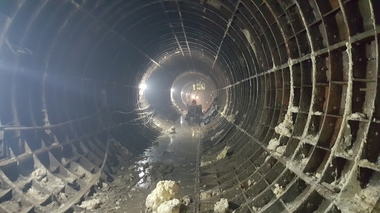
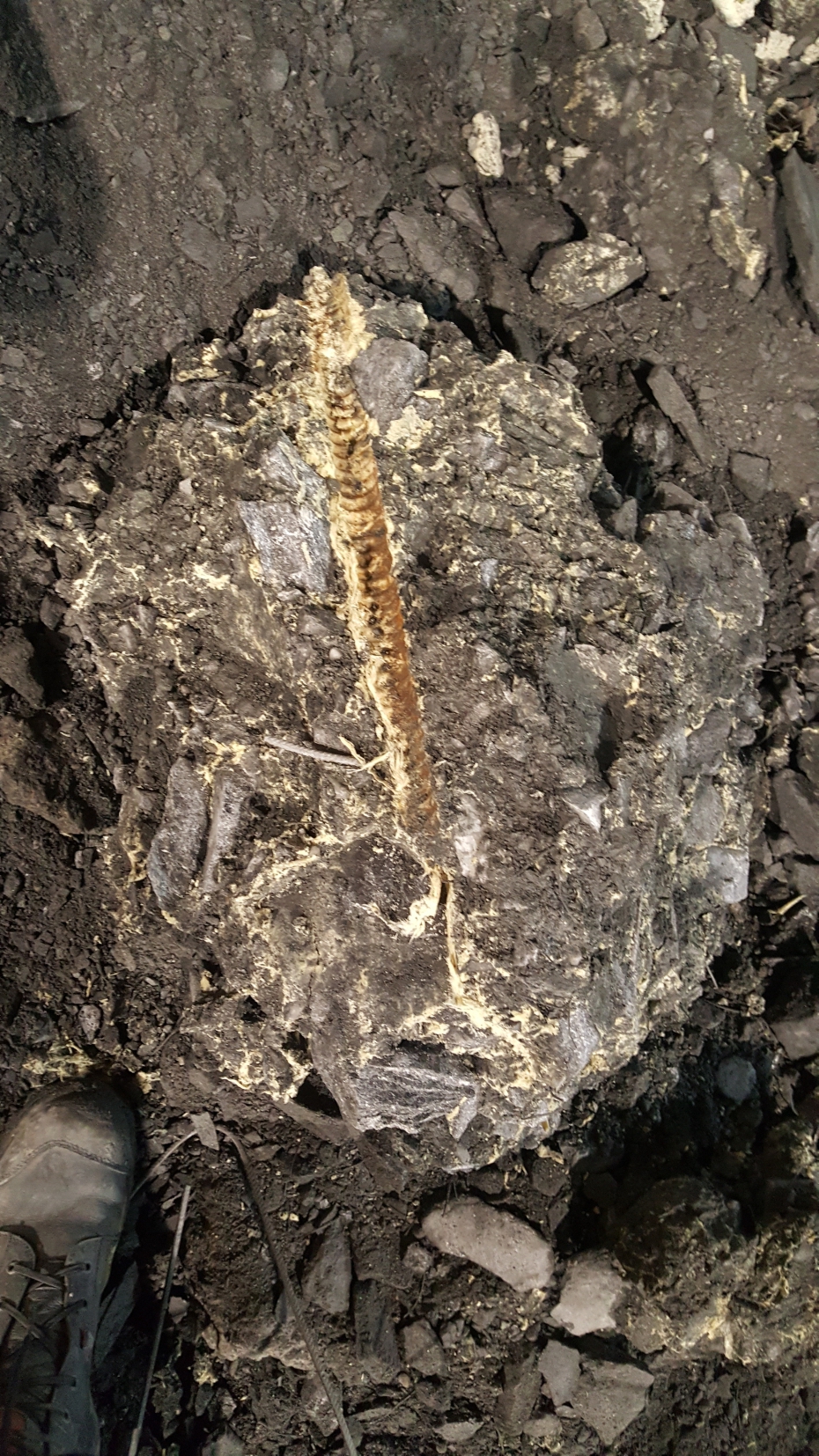
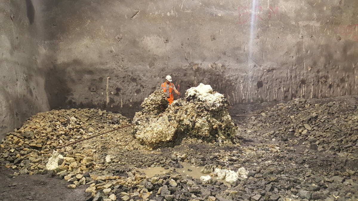
Fig. 2 shows the first test in the site facilities cavern (the future emergency station). Fig. 3 shows a detailed view of a grouted area, with the adhesion effect nicely visible. Originally loose, non-cohesive material was turned into a solid block through the injection of foam. It can also be easily seen that the injected foam (yellowish) has scarcely foamed or not foamed at all in the small cavities, so it has adapted itself and glued the material together very well. Fig. 4 shows the second test in relatively blocky material. This test was undertaken to assess the foaming behaviour with respect to its foam factor and its adhesion in larger cavities. The assessment of these two large-scale tests completely confirmed the suitability of this PUS as the injection foam.
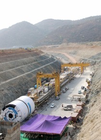
2.2 Mechanised Tunnel Drive
The regular tunnel drive of TBM 2 began on April 29, 2019, almost one year after TBM 1, which made it possible to transfer experience from TBM 1 to the second machine. Regarding the foam injection, there was a question about whether any consolidation in one tube would affect the other tube.
This report is based on experience up to the end of March 2020, by which time TBM 1 had successfully driven 3434 m of 8264 m, and TBM 2 had driven 2811 m of 8128 m – both machines therefore less than halfway through their drives. The best advance rates were 31 m on one day (TBM 1) and 548 m in a month (TBM 2).
2.2.1 Start of Injections
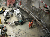
The site was prepared for the grouting works. During the tunnel drive, it turned out that fault zones were easily spotted:
through a very obvious increase of the cutterhead torque from 2000–4000 KNm to up to 15 000 –16 000 KNm with peaks over 18 000 KNm (note: the maximum torque is 22 000 KNm)
and through a clearly visible extra volume of conveyed material on the belt (from an intended value of 430 t (for each 2 m stroke) up to 1000 t)
The machine effectively came to a stop with no further progress possible.
The intended injection locations were the manhole, the bucket openings and the disc boxes. The prepared injection lances were 1.5–2.5 m long unperforated steel tubes with a diameter of 0.5 inch or, for the really loose areas, self-drilling glass-reinforced plastic (GRP) injection bore (IBO) anchors of the same length. The lances were inserted into the loose areas and the PUS injected through the lance using a two-piston pump, Y-piece, static mixer and connecting hose. The agreed injection stop criteria were visual assessment, visible emergence of foam or a strong increase of the pump pressure, which was however mostly assessed acoustically. The injection pressures measured at the pump were between 20 and 130 bar, and the grouted volumes were in the range of single figures of tonnes for the entire grouting work for one machine stoppage. The required two-component PUS injection foam was delivered in canisters, which also permitted very efficient control of the uniform volume flow. The resin was injected in a ratio by volume of 1:1 (A+B), which was very easy to check from the number of empty canisters after each grouting phase. The measured pumping times were about 5–10 hours.
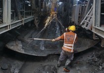
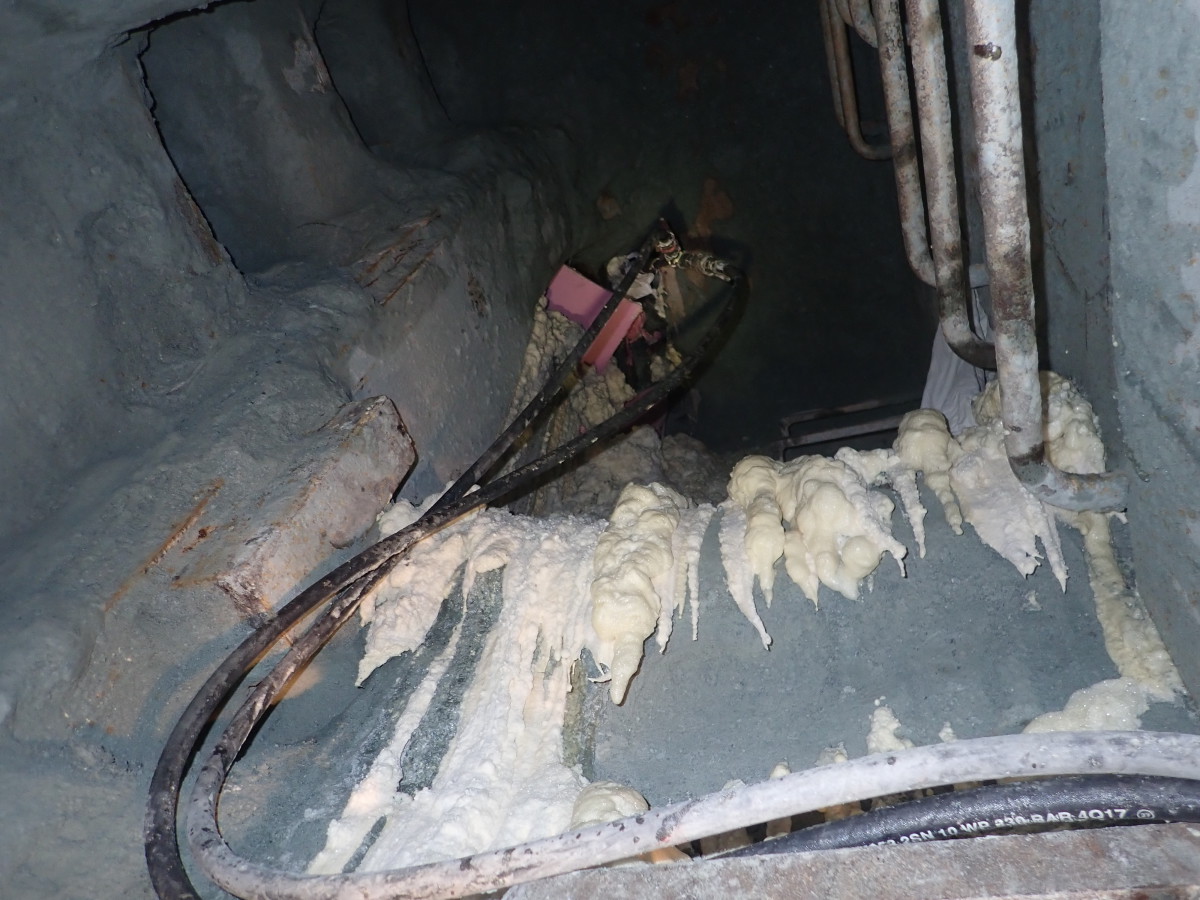
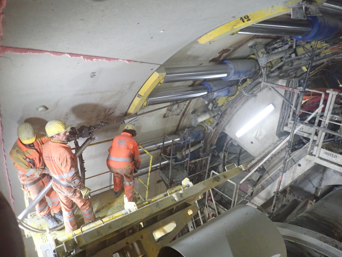
Fig. 5 shows a foam injection from the cutterhead, with the restricted and thus not ideal conditions being apparent.
The emerging foam shows the end of the injection process.
At this time, the following working rhythm had become established for fault zones: stop to inject foam from the cutterhead area with lances about 2 m long; an advance of 2–4 m; another stop to inject foam and so on. Advancing further was not possible because it led to exactly the same observations that had preceded the stop a few metres further back. The end result was a rather inefficient and rapidly alternating stop-and-go operation over 2–4 m in each case.
The identified time waster was the injection times. To reduce these, great attention was paid to the extra conveyance of excavated material. The machine stop criterion was reduced from ≤ 1000 t to 600–700 t per 2 m stroke, which still corresponded to an extra quantity of about 50 % compared to the theoretical quantity of 430 t. This was based on the consideration of potentially losing less of the original rock mass strength and thus needing less injection material. However, this did not lead to a noticeable acceleration of the tunnel drive.
The limiting factor for efficient operation was clearly the limited reach of the foam injection from the restricted working areas, which therefore had to be increased. Since the available injection points did not permit the use of longer lances, new injection points had to be found to permit injection with a much longer reach and in larger volumes.
2.2.2 The improved Injection Approach
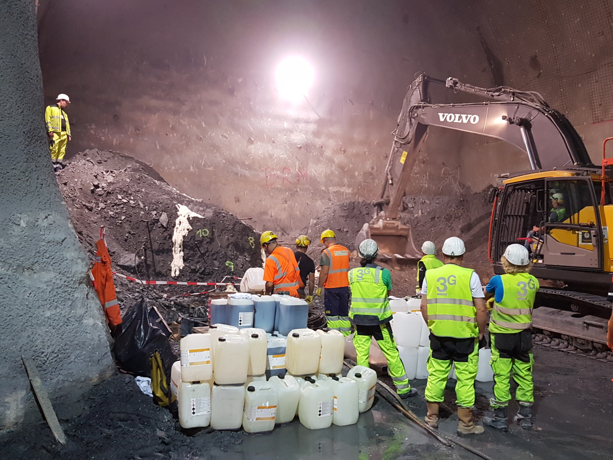
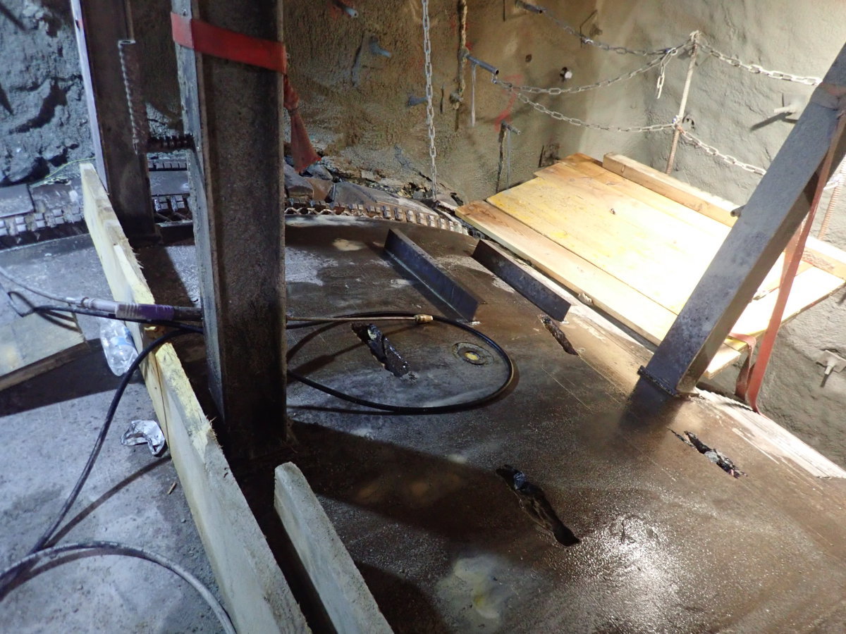
The only sensible location for new injection positions was the area under the protection of the TBM shield. Injection holes thus had to be cut through the shield. A decision was made to make slot-shaped openings to gain much more flexibility regarding the drilling and injecting angle. Seven slots were made at about 10:30 to 13:30 on a clock face. Fig. 6 shows these slots, where you can also see their proximity to the cutterhead (the photo was taken during overcutting of the crown). The slots were closed with covers during the advance.
The flexibility gained with this approach allowed much deeper injection holes to be drilled. The lengths of the injection lances and the GRP IBO anchors now varied from 2 to 7 m, with lengths greater than 4 m perforated for the last 1.5–2 m (also the GRP anchors) to enable better foam injection. Graded lance lengths (two per slot) were also used, with injection always starting at the deepest point.
The injection stop criteria were again specified as emergence of foam or an increase of the pumping pressure to 180 bar. At the end of each injection, the inserted lances were flushed to make them available for further use. This way foam was being injected through all the slots. Then the lances were injected a second time, and a third if required. This was intended to fill cavities as thoroughly as possible and to improve the geotechnical properties of the rock mass. The works could now be carried out with much more space in a well secured area, as can be seen in Fig. 7.
The best possible time for the start of grouting was based on the already modified approach, that an increase by
50 % of the spoil conveyance would cause the machine to stop. An increase to 85 % of the maximum torque also became established as a reason to stop. This was necessary because before the establishment of this threshold, it was sometimes not possible to turn the cutterhead again and it had to be cleared manually after the completion of grouting. The reacting, pressing force of the cutterhead was also observed more closely since a rise indicated an unstable face, sometimes even a collapse from above.
It immediately became apparent that much more material was being injected at each stop. The volume amounted to about 20–50 t per intervention, which also showed the intended success immediately. After restarting, the TBM could be driven another 6 m (three strokes) without problems and without any indication of a disturbed rock mass. With the greater volumes being injected, the PUS resin logistics were changed over from canisters to IBCs (Intermediate Bulk Containers), which contain 1 m³ of material. The uniform supply of components A and B to the pumps was checked by marking the fill level of the IBCs. The advance through fault zones still continued in stop-and-go operation, but uninterrupted advance was now possible for three strokes, sometimes four.
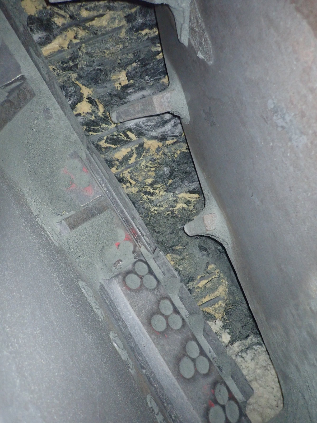
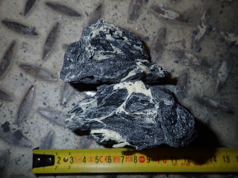
Figs. 8 and 9 show examples of successful grouting. Fig. 8
shows a view of the injected area through the bucket opening of the cutterhead, with the yellow traces of the PUS foam clearly visible. Fig. 9 shows a consolidated and already conveyed lump of rock.
The aim of enabling relatively efficient boring through fault zones using foam injection had thus been reached. It should however also be mentioned that additional grouting has to be carried out subsequently in the areas that have already been glued and consolidated with foam (see ZM9 under 1.1). This grouting is carried out through the segment lining and is intended to fill any cavities still open near the tunnel to ensure permanent adequate bedding of the lining.
2.2.3 Comparison of the Two TBMs
As already mentioned, the first tunnel boring machine excavated its tube ahead of the other. Since the axial spacing of the tubes is between 40 and 70 m, reciprocal influencing of one tube on the other was not really expected.
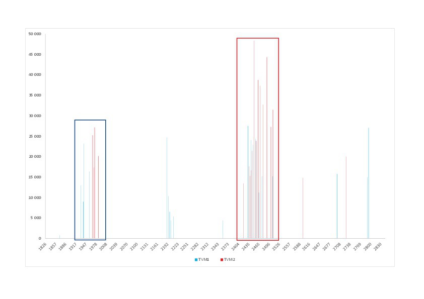
It is possible to draw a diagram of the grout consumption over the tunnel length and thus compare the two TBMs. TBM 1 started boring in tube 2, and TBM 2 followed months later in tube 1. Grouting volumes are shown in Fig. 10, with the slight chainage offset ignored as a simplification. The considered excavation of about 1000 running metres of tunnel shows the following picture: grouting is carried out in TBM 1, and this is sometimes repeated at the same chainage and with the same volume in TBM 2. The volumes marked with a blue rectangle are about the same. At other chainages, smaller volumes were apparently injected into small-scale faults in TBM 1, which was not necessary for TBM 2. One significant exception is chainage 2450–2490 m, which is marked with a red rectangle in Fig. 10. Observations about this section are now described and discussed.
As TBM 1 passed through, it turned out that much larger quantities had to be injected to stabilise this fault zone, with eight stops in total for grouting. The TBM drove out of the fault, and the installed segment lining showed increased loading through increasing deformation and cracks. In order to stabilise this section, additional grouting was carried out through the lining (ZM9), with cement suspension being used as grout. An injection depth of 1.5 m was specified, with 2 m-deep injections carried out. This measure was sufficient to stop the deformations.
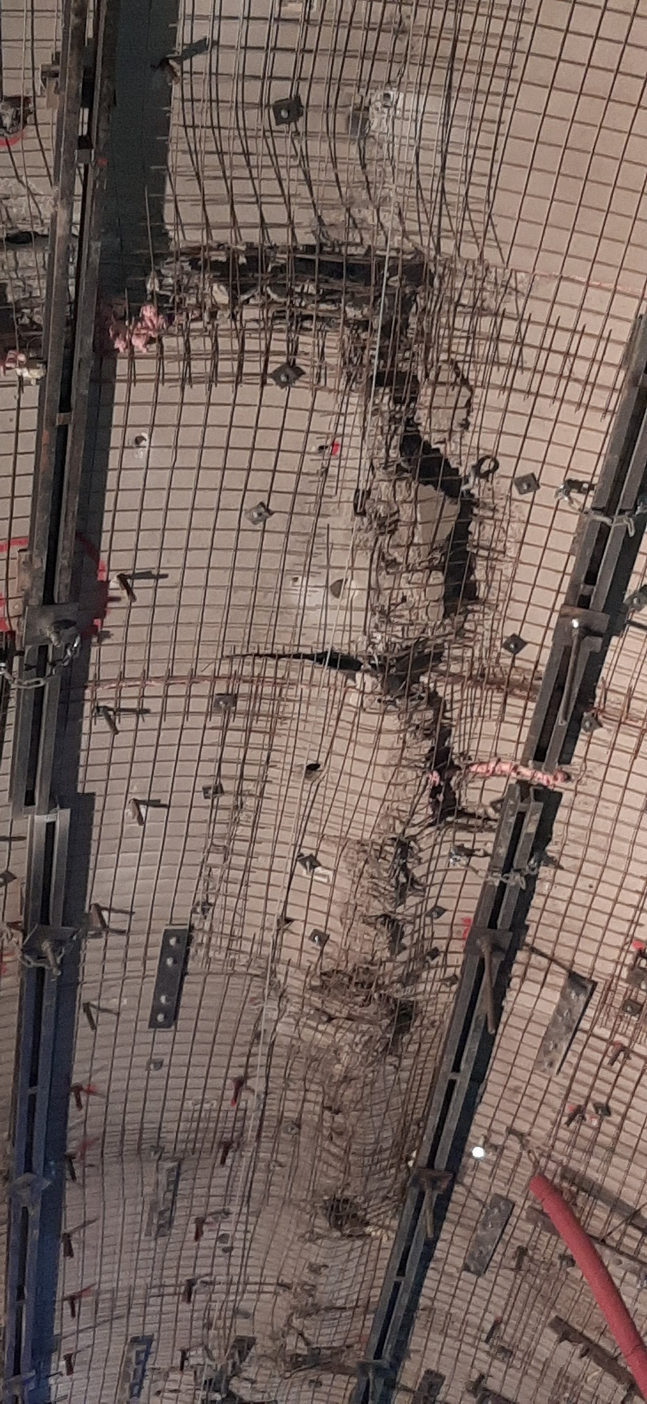
About four months later, TBM 2 drove through the same fault zone at an axial distance of 40 m from the already driven tube (track 2). The foam volumes injected under the same stop criteria were 2.5 times greater than previously with TBM 1, and 15 grouting stops were necessary. As TBM 2 was passing through the fault zone (tube 1), a renewed increase of deformation was observed in tube 2 (TBM 1), and the cracks in the segments became larger (Fig. 11).
TBM 1 was stopped and it was decided to remove the loose segment parts and replace them with shotcrete. A shotcrete inner lining strengthened with mesh and U-profiles was also installed in the extended crown area. These measures had the intended impact and stabilised this section.
What conclusions can be drawn from this?
TBM 1 bored through a fault zone, which was partially consolidated with injected foam. The volume balance of the belt weigher indicated significant overbreak, which was only partially backfilled with foam. The remaining rock bridges led to a very uneven loading of the lining and to the observed cracks, which were stopped with more grouting very near the lining. This resulted in a system with a factor of safety of slightly greater than 1. Any additional loading would make the scarcely stable state unstable again (it should be noted here that it is much easier to make this observation with hindsight).
TBM 2 drove into the same fault zone and consumed much more grout. It cannot be assessed here whether this was due to local reduction of rock mass strength by the earlier passage of TBM 1 or whether other reasons were decisive. In any case, load transfer from the excavation of TBM 2 reached the other track and led to additional loading, which once again overloaded the just stabilised lining.
It can therefore be said that, despite the very large axial spacing of 40 m, there was reciprocal loading of the tunnel tubes in this fault zone.
3 Conclusions
It has been clearly demonstrated that the injection of PUS foam as a tunnel advances can lead to considerable improvement of the rock conditions and, in some cases, it is necessary to enable a successful TBM drive in the first place. The preliminary tests carried out in the cavern proved a successful way to ensure that the grouting measures were as efficient as possible.
For injecting from the machine, it was found that longer lances, or drilling that reached further forward, reduced the continuous alternation between stoppage and grouting and thus enabled more efficient tunnelling. This required the provision of suitable injection slots in the machine, which enable variable and multi-stage injection and are also useful for the geologists as viewing slots.
Regarding the criteria for stopping the machine and starting grouting, it can only be said that these should indeed be specified at an early stage but must be continuously adapted to the specific requirements on site.
A geotechnical consideration of the grouting measures is generally very advantageous, although with larger fault zones, more attention must be paid to deeper rock mass consolidation. For this purpose, deep initial or subsequent grouting is expressly recommended – and not only for the case of a second parallel tube.
Finally, the authors wish to thank Austrian Railways ÖBB, who have made the publication of this article possible.