Double Shield TBM for Indian Water Tunnel
Porous phyllite, heavy water inflows, and faulted geology have been just a few of the challenges at India’s Pula Subbaiah Veligonda Tunnel Project. Unusually hard rock combined with a long tunnel length (19.2 km) has required careful machine design and maintenance of the 10.0 m diameter Robbins Double Shield TBM. Probe drilling and pre-grouting have been paramount in keeping the machine moving in the difficult conditions.
Project Background
Eastern areas of India’s Andhra Pradesh state receive only 20 cm of rainfall per year - an amount comparable to Africa’s Kalahari Desert. The Andhra Pradesh Irrigation Department hopes to alleviate the chronic drought conditions and contaminated drinking water in the region with a massive water transfer scheme consisting of over 120 km of tunnels, all sourced at the Srisailam Dam on the River Krishna.
At the right bank of the Srisailam Canal lies the future inlet site for the Pula Subbaiah Veligonda Project, one section of the overall water transfer scheme. Once complete in 2014, the Veligonda system will draw 1.2 billion m3 of flood water annually from the foreshore of the Srisailam reservoir. Two parallel, 19.2 km long tunnels will transfer water via a network of 5 canals to over 1,600 km2 of farmland in the 3 districts of Prakasam, Nellore and Kadapa. Up to 243 m3/s of water will travel through the bored tunnels to a feeder canal.
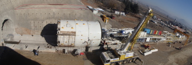
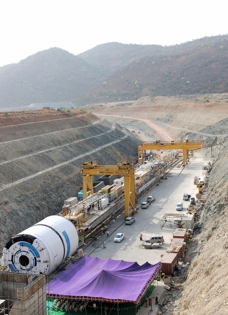
The 180 million USD contract was awarded to the Coastal Projects Ltd (CPL)/Hindustan Construction Company (HCC) JV. A Robbins Double Shield TBM and continuous conveyor system, as well as spares and key operating personnel, were supplied to the jobsite to excavate tunnel no. 2 starting from the outlet end. The machine was launched in June 2009.
Tunnel No. 1 is currently under excavation by the NSC Consortium – a JV of local firms Nuziveedu Seeds, Swathi Constructions and Coastal Projects – using a 7.9 m diameter Herrenknecht Double Shield.
Abrasive Hard Rock Conditions
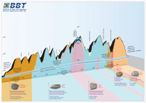
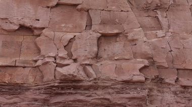
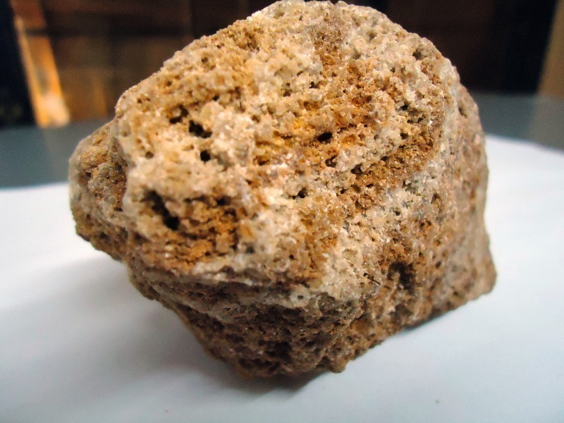
The Veligonda tunnel path is located in sedimentary rock on the western margin of the Cuddapah Basin, where a number of faults and folds make for complex geology. Rock includes quartzite with interbedded shale (60 %) and shale with limestone and phyllite (40 %). Two major faults are expected along with some ground water.
In general, the high quartz content of the rock in the Veligonda tunnels tends to cause high abrasive wear during tunnelling, making larger diameter, 20-inch disc cutters the best option for longer cutter life. The quartzite sections with interbedded shales can also be very blocky in nature – the layering of hard quartzite with thin, weak shale makes over-break in the crown and shoulder of the tunnels a possibility.
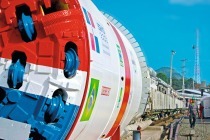
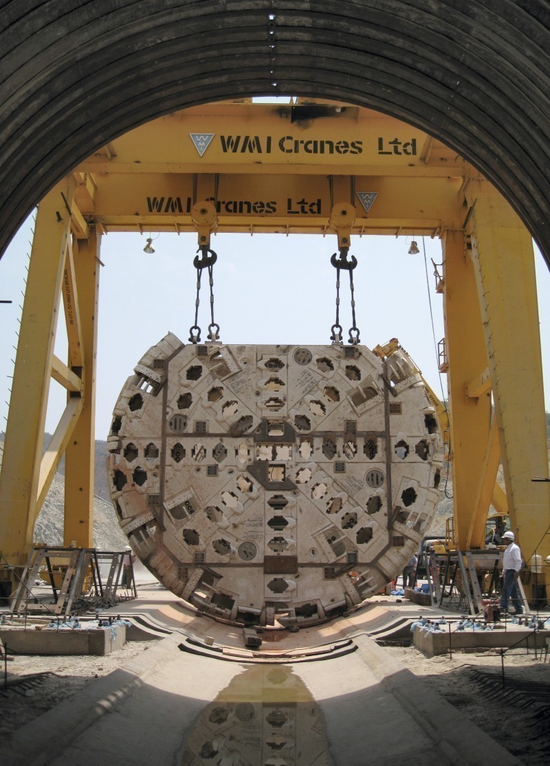
Machine Design
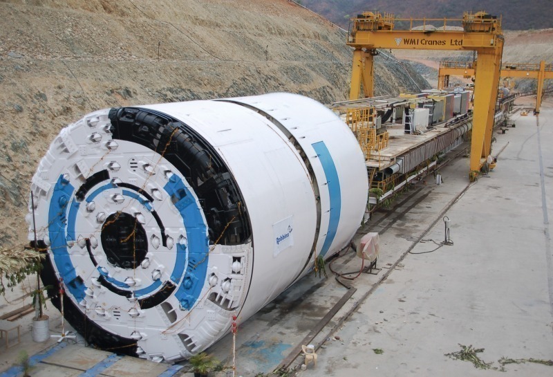
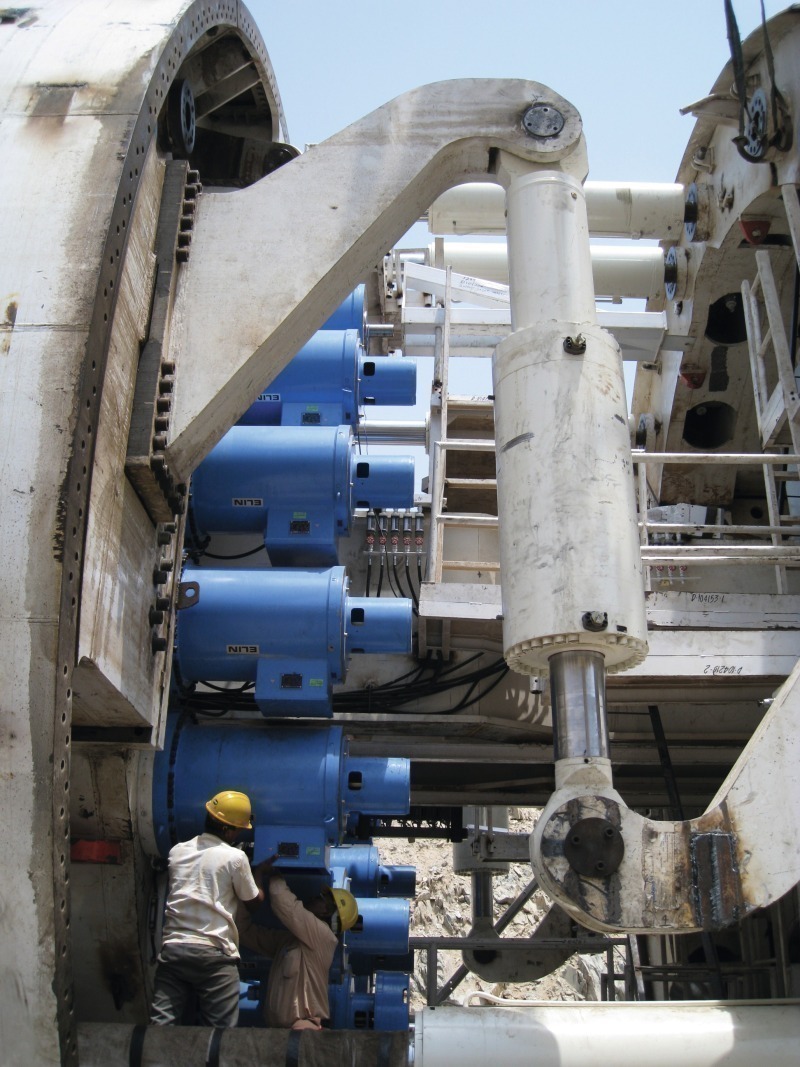
The 10.0 m Double Shield TBM is mounted with back-loading 20-inch diameter cutters for more efficient excavation, particularly in the high rock strengths present. Specially designed drive motors also allow the machine to run at a higher than normal RPM, compensating for low penetration rates in sections of extremely hard rock. In squeezing ground, the cutterhead is also capable of vertical movement to allow for overboring.
Continuous lining behind the machine consists of 300 mm thick concrete segments in a 6+1 arrangement, making the finished tunnel diameter 9.2 m. Stability of the segment rings is achieved through a combination of crushed aggregate injection and grouting to fill the annulus outside the lining.
A probe drill mounted on the machine allows for verification of geology 30 m ahead of the TBM. The drill is capable of 360º rotation and can alternatively serve to drill grout holes for ground consolidation. Large 40 kW dewatering pumps located on the back-up systems have been specially designed to pump any water away from the tunnel face.
To monitor TBM performance throughout the project, a newly designed data logging system was installed on each machine. Real-time meters allow the measurement of parameters including cutterhead motor amperage, RPM, cutterhead power, and gripper cylinder pressure. Information can also be downloaded for viewing by the tunnel superintendent and engineers at the surface, to allow monitoring and adjustment of all TBM equipment.
Conveyors for Long Distances
The bore path behind the TBM is nearly straight, making a powerful steel cable belt system a good option. The Veligonda system tops out at 19.2 km, making it the longest single conveyor flight Robbins has provided. The setup also allows maintenance and belt splicing to be performed outside of the tunnel in an optimal environment. The long steel cable belt system is powered by a total of 4 drive systems – 1 main drive with two 300 kW motors at the tunnel portal plus 3 booster drives inside the tunnel.
Once outside the tunnel in the spoil handling area, muck is transferred to spoil dumps using trucks. The excavated rock from the TBM drive is then recycled for use as concrete aggregate and pea gravel.
Initial Tunnel
Excavation
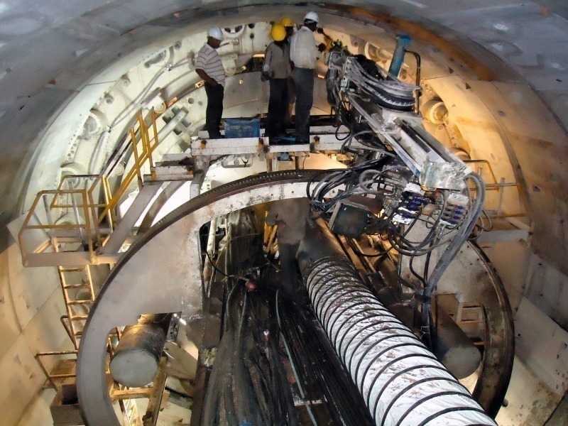
Crews began excavation of Veligonda tunnel No. 2 in June 2009, through mainly soft, fractured rock with little water ingress. An international crew of workers, combined with local staff in training, was assigned to the site to keep the TBM in operation for two 10-hour shifts, plus a 4-hour maintenance shift. Typical operations during the shifts included ring building, pea graveling, and grouting to control any water inflows. During rotations the Robbins crew stayed at a campground and living facilities 2 km from the portal site, with electricity, air conditioning, and internet service.
Trouble at Tunnel No. 1
By December of 2009, both TBM were operating in the parallel tunnels, with the Herrenknecht Double Shield several km ahead since it had started months earlier. Approx. 3.39 km into tunnelling, the machine bored into an unforeseen area of disturbed geology, consisting of a significant shear zone between the quartzite and phyllite rock. High pressure water was also present and the machine was inundated with flowing material consisting of fractured quartzite rock, fine grained sand, and clay. The machine became stuck and a bypass tunnel was excavated over the crown in an attempt to free the trapped shield, but this was also flooded with flowing material.
Material thus had to be re-excavated from the bypass tunnel, and a second tunnel was driven to drain the water from the first bypass. By February 2011, the bypass tunnel was approx. 10 m in front of the machine, and hand excavation at the front of the TBM cutterhead had commenced. To date the machine has not moved since 16 December 2009.
Pre-Grouting and Probe Drilling at Tunnel No. 2
As of February 2011, tunnelling at the 19.2 km No. 2 tunnel had advanced approx. 3.5 km at rates of up to 330 m/month. Ground consisted of abrasive hard rock paired with highly porous phyllite of low UCS-conditions nearly identical to those in Tunnel No. 1. The machine was also excavating in transition zones between quartzite and phyllite, though the flowing material seen in the neighbouring tunnel had not been encountered.
During tunnelling, the phyllite and quartzite material is crushed into fine-grain silt and sand, which has presented problems during repeated water inflows of up to 9,000 l/min. The high levels of water can wash the abrasive silt and sand into the telescopic shield and tail skin area of the machine, requiring diligent pumping and cleanup efforts.
During inflows, water is pumped out of the tunnel, which is being driven at an upward gradient. Pumps transfer the water behind the TBM back-up and into the central drainage channel built into the invert segment structure. Another set of pumps is then used to transfer the water from the tunnel portal to separation tanks. Pre-injection grouting is being used extensively to reduce the severity and number of water ingress events.
Detailed Program
Pre-injection grouting and probe drilling were seen as the main methods to prevent a recurrence of the unfortunate events in Tunnel No. 1. The biggest challenge was in improving the efficiency of the probe drilling and pre-injection grouting operations. Robbins assisted the contractor CPL in this process by providing a detailed methodology, as well as redeploying experienced personnel from other Indian projects to supervise the efforts.
Prior to a push, 3 probe drill holes are bored between the 3 o’clock and 9 o’clock positions of the tunnel circumference, depending on the ground conditions. The TBM was designed with numerous holes for drilling and grouting through the shield. Probe drilling is done to the maximum length in front of the machine, approx. 30 m, if no adverse conditions are encountered.
Grouting is done using OPC grout pumped in at a pressure of 60 bar. Between 5 and 14 grout injection holes are used to pump the material in at depths of 25 to 30 m. If necessary, more grout holes can also be utilized to ensure that grout reaches the tunnel invert as well. Afterwards, secondary grouting is carried out to determine the extent of migration and of the general effectiveness of the primary grout. Distances between each grout canopy range from 5 to 20 m depending on ground conditions. This technique was utilized successfully throughout the shear zone that affected excavation in Tunnel No. 1.
Conclusions
The events at the Veligonda tunnels have underlined the importance of probe drilling and pre-grouting in preventing unplanned stoppages. Geology in the project area was surveyed and was not thought to be particularly challenging. However, the two 10.0 m Double Shields at the nearby AMR water tunnel and the 2 TBM at Veligonda are the first sets of machines ever to bore in Andhra Pradesh state.
Other Indian projects have also encountered stoppages of a year or more, such as the Tapovan-Vishnugad hydroelectric power project in Uttarakhand. India’s difficult geology, particularly Himalayan rock, requires rigorous foreknowledge of the ground directly in front of the machine. Extensive pre-grouting and probe drilling programs are ways to mitigate these risks when tunnelling in difficult rock conditions.