Extreme Working Conditions: The Rohtang Road Tunnel in the Indian Himalayas
Extreme working conditions at an altitude of more than 3000 m above sea level, water ingress of more than 250 litre/sec, high rock pressures with extreme deformations and rapid changes in rock formations presented major challenges during excavation of the Rohtang road tunnel in the Himalayas. At the 2020 Salzburg Geomechanics Colloquium, Peter Reichenspurner and Thomas Riedel of contractor Strabag explained how the logistics and conditions pushed the NATM excavation and the crews of the joint venture with Afcons from India to the limit during the 10 years construction period from 2009 to 2020. The awarded value of the contract was about 250 million euros.
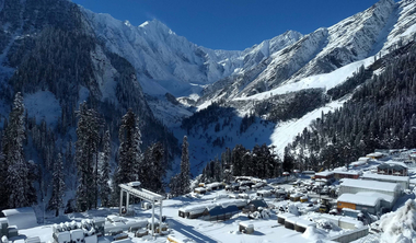
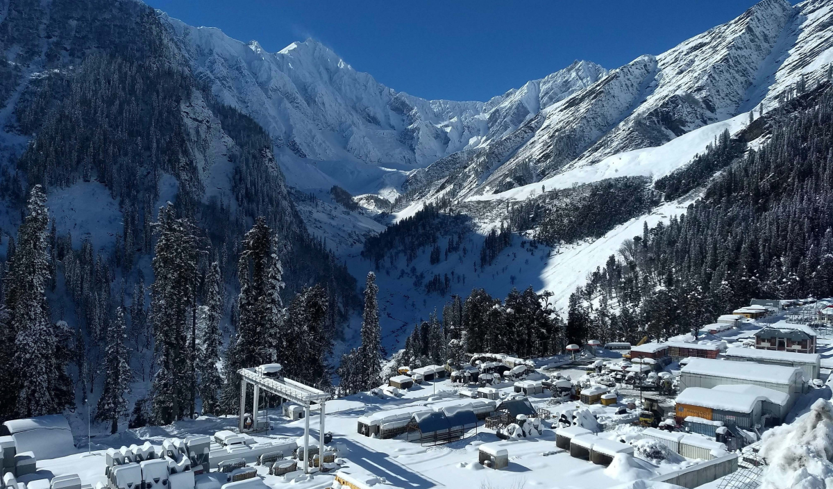 Rohtang construction site at the South Portal high in the Himalayas
Credit/Quelle: Reichenspurner/Riedel/Strabag
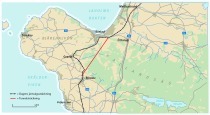
The 8.9 km long, single-tube two-lane tunnel was built to avoid the dangerous route over the Rohtang Pass at 4000 m above sea level. The new link shortens the Manali–Leh Highway by about 50 km and provides a route between Himachal Pradesh State and the union territories Jammu and Kashmir over the whole year.
A significant challenge was the high altitude The low oxygen content in the atmosphere affected personal health and caused a loss of equipment performance. Getting to the job site was an additional challenge due to load restrictions on bridges, landslides, falling rocks and extreme weather conditions on the local road. Under these conditions, construction work at the north portal was only possible for about six months a year.
Excavation was planned to progress using drill + blast from both portals. The 13 m wide excavation accommodates two traffic lanes, two footpaths and an emergency egress beneath the carriageways. The two-lane cross section with one lane in each direction has a gradient of 1.5 %. Entry points to the emergency egress underneath the carriageways are provided every 500 m. The unreinforced cast-in-situ final concrete lining, which has no waterproofing system, is 50 cm thick. An intermediate ceiling slab provides for transverse ventilation and smoke control.
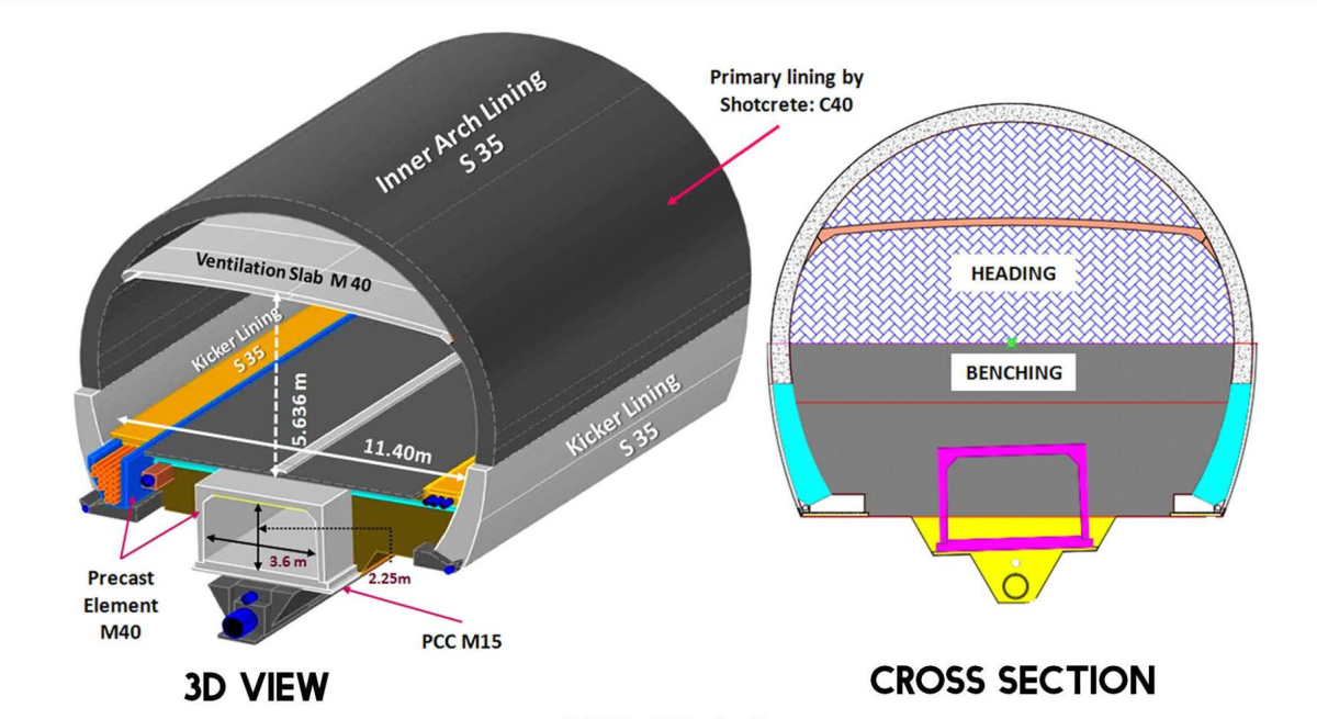 Design of the two-lane road tunnel
Credit/Quelle: Reichenspurner/Riedel/Strabag
Drill + Blast Excavation beneath an Overburden of up to 1900 m
Drill + blast excavation beneath an overburden of up to 1900 m started in 2010. Work progressed on a top-heading, bench and invert sequence on a cross section that ranged from 140 to 205 m2, depending on the excavation class.
With the rock formations unsuitable for determining existing excavation classes, a change to NATM was incorporated into the design in subsequent revisions and the behaviour was stipulated as an additional criterion. This meant that monitoring of the rock behaviour was an essential part of the NATM.
After progressing 1.9 km from the south portal, the first fault zone was encountered and the NATM was adapted to conditions by:
modifying the length, spacing and diameter of the pipe umbrella pre-support,
adding support with additional anchors and rockbolts,
altering drive sequences including sidewall drifts,
applying reinforcement mesh directly on the excavated rock before shotcreting,
adapting the drainage system with a dimpled membrane on shotcrete and 600 mm drainage pipes in the invert,
inserting a waterproofing system as part of the final concrete lining design and
reducing the gradient of the carriageway to avoid dismantling of the pipe umbrella pre-support.
Fault Zone
At about 1.93 km top-heading drive, the entire face consisted of loose material with heavily fractured, shattered rock and soil. Horizontal deformations combined with severe cracking resulted in the initial failure of the drive. Water ingress increased, with up to 150 litre/sec inflow recorded from the top-heading face alone.
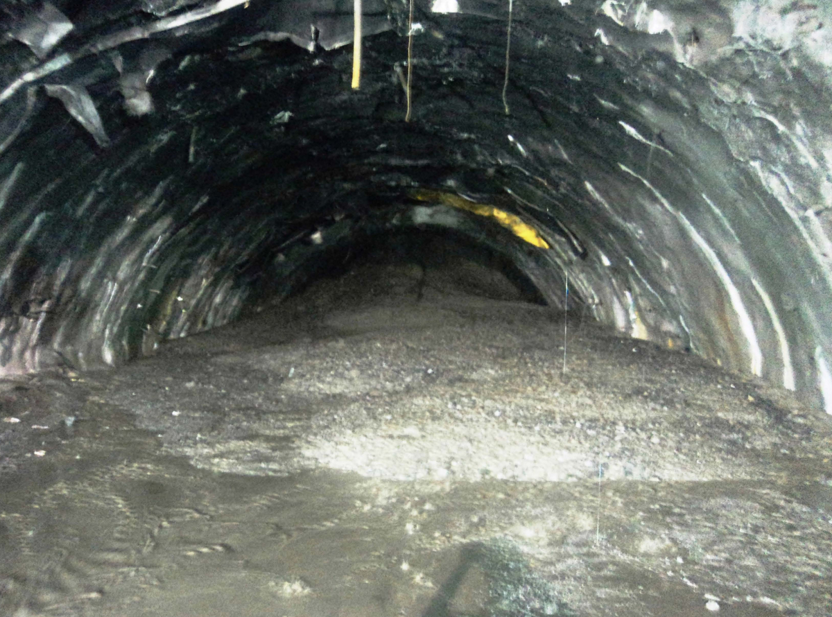 The largest influx of material with 1000 m3 at 2.08 km of the tunnel
Credit/Quelle: Reichenspurner/Riedel/Strabag
At 2.05 km a major collapse occurred causing an inflow of about 400 m3 of water-saturated material. At this point the excavation moved into a main fault zone. Several further collapses occurred as the drive progressed. The largest inflow of loose material was about 1000 m3. Due to the high level of water ingress, cavities formed primarily in the crown area. At 2.4 km the pipe umbrella pre-support collapsed with deformations in excess of 800 mm recorded in the crown. The area was recovered with timbers and shotcrete. The conditions were subsequently directly linked to a watercourse on the surface. At 2.46 km the heading was again mapped as a rock.
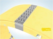
As the heading approached the main identified fault zone, new excavation classes were defined to increase the support resistance. Additional anchors were installed following localised rockfalls, and drainage holes and drainage pipes were inserted to manage water ingress. Pipe umbrella pre-support was installed on 15 m rounds at the start of the main fault zone. As geotechnical and geological conditions deteriorated, the pre-support pipes were lengthened, the pipe diameter was increased from 76 up to 114 mm, and the pipe rows were doubled and the spacing reduced.
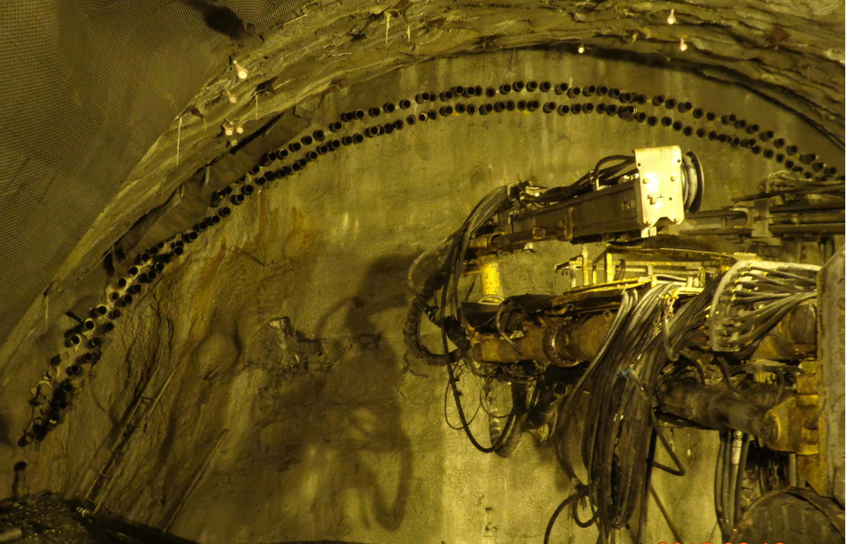 Lengthened, double-row pipe roof with larger pipe diameters
Credit/Quelle: Reichenspurner/Riedel/Strabag
After various trials with pilot and side drifts, the top-heading was eventually advanced in sequential drifts with additional stabilisation measures. Depending on the situation, shotcrete and spiles were used in the face. In some cases longer face spiles with microfine cement grouting, micro piles in the area of the crown as well as consolidation and sealing grouting was required.
Squeezing Rock Conditions
In some areas of the north drive, the primary steel-fibre-reinforced shotcrete behind the face flaked off. According to project managers Reichenspurner and Riedel this was caused by the biotite schist encountered and was largely mitigated by switching to steel mesh reinforcement. In addition to shotcrete cracked and spalling off, squeezing rock conditions caused rockbolt plates and lattice girders to buckle, and stress release rock bursts occurred in areas of more than 1500 m overburden up to 200 m backwards from the face.
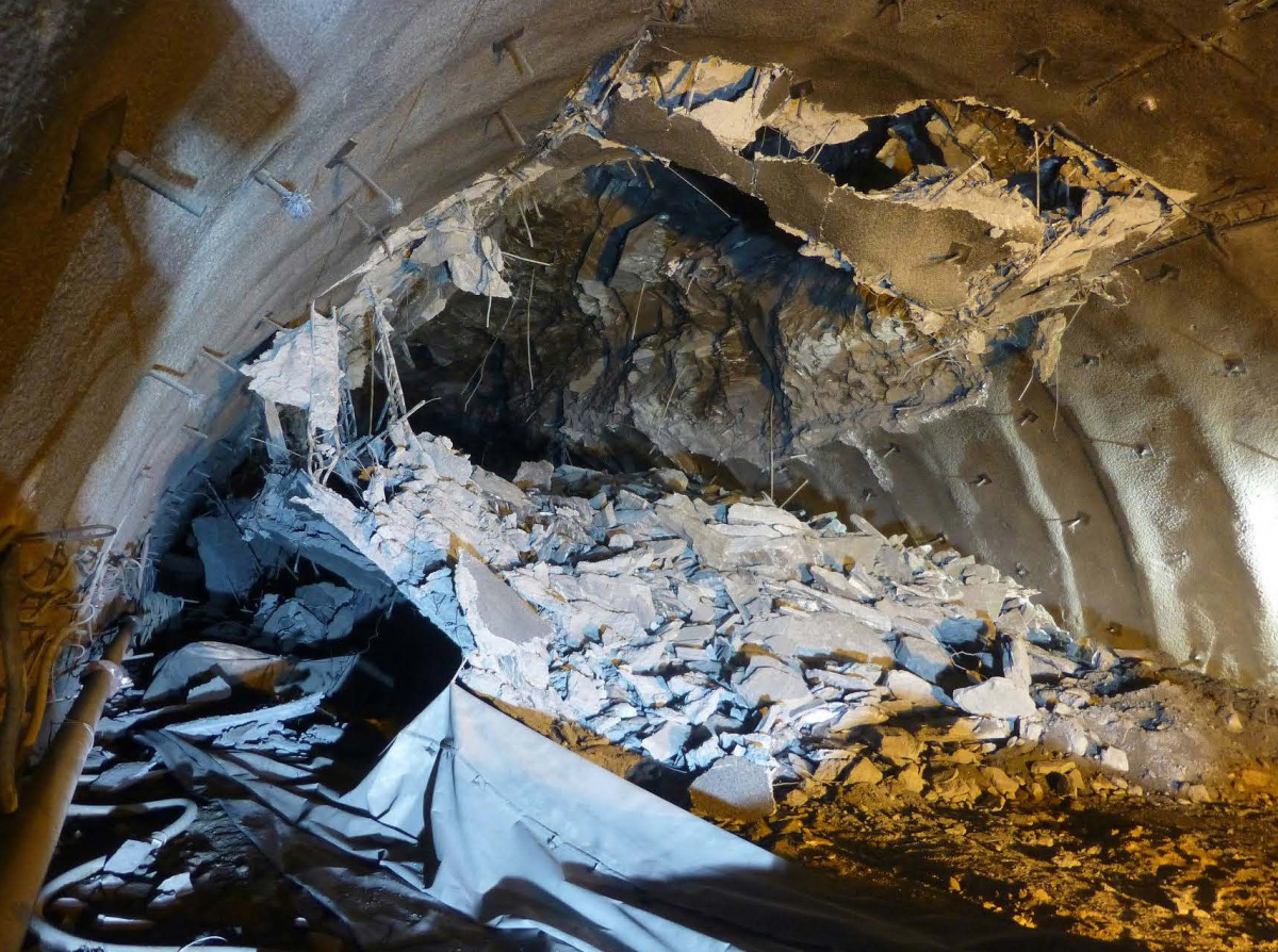 Collapse in the north drive 70 m behind the face
Credit/Quelle: Reichenspurner/Riedel/Strabag
To manage these deformations, numerous adjustments of the design excavation classes were undertaken to strengthen support resistance and adjust round lengths and the construction process, sometimes within an advance cycle. Applying adjustments quickly played an important role. The largest deformations were checked by providing deformation slots along the tunnel axis and inserting lining stress controllers. After 10 years of hard-won progress, the completed tunnel opened to traffic on 3 October 2020.

