Fire Protection for new and existing Underground Structures
The new EU directives and up-coming legislation decree that all the major existing road tunnels need to be upgraded to the latest safety requirements over the coming years. As a consequence, higher demands are placed upon fire protection systems required to fulfil not only fire protection and fire life safety requirements but also provide the most economical and durable solution for the given risks in the tunnel. Owners and designers must endeavour to choose the optimum solutions for the given circumstances.
High durability concretes have become a prerequisite to increase the design life of structures. In order to achieve these high durability requirements, concrete is designed to have low permeability and hence poor performance in case of a fire with higher probability of spalling. This was evident in the dramatic Channel Tunnel fire in November 1996, which resulted in almost complete loss in concrete section.
There are many ways to protect a structure from the negative effects of heat, however thermal barriers emerge as the most robust and fit solution to protect against both the mechanism of spalling and that of strength loss caused by the exposure of concrete structures to elevated temperatures.
Over recent years, a number of notable tunnel fires in Europe have led to the tragic loss in human life. In addition to this immensely ill-fated consequence, it is worth considering the structural damage that may occur following a fire in a tunnel environment, that can also cause, even if indirectly, severe danger to users.
Structural damage to tunnels implicates repair work at elevated costs as well as extended periods of loss in service (Table 1) to which one can add the negative effects on tourism, the micro-economy, the value of the structures etc.
Numerous bodies have begun to investigate tunnel user safety and methods of protecting the structure from fire. Active fire protection systems, which include water sprinklers, water mists and foam deluge systems, act directly on the fire and smoke element to reduce their effects before the situa-tion escalates out of control. Passive fire protection systems, on the other hand, comprise all solutions aimed at protecting the tunnel structure from the fire. This article will focus its attention to the passive fire protection of underground structures.
When concrete tunnel linings are exposed to fire, the following structural issues need to be considered:
– concrete typically undergoes explosive spalling, and will continue to do so until there is no concrete left, or the fire diminishes;
– concrete loses structural strength at elevated temperatures; and
– steel reinforcement loses tensile strength at high temperatures.
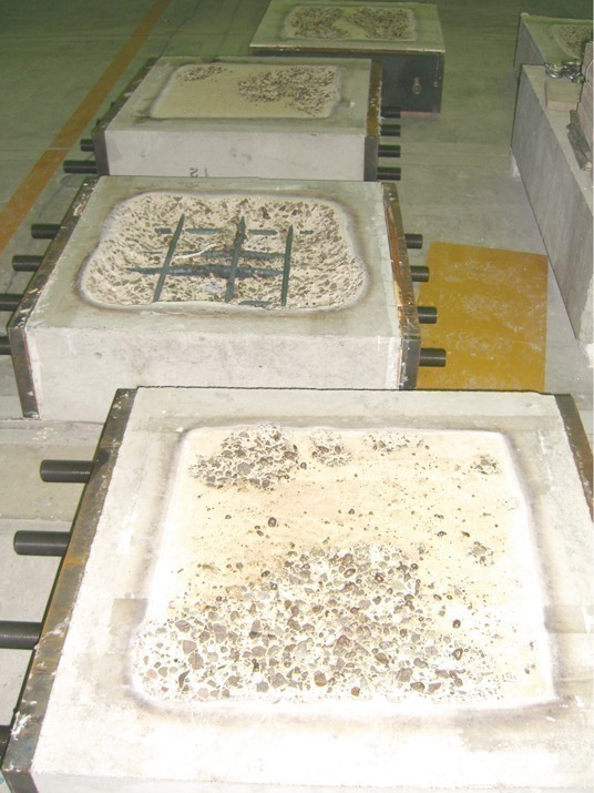
The spalling phenomenon causes the violent detachment of fragments of the structure with consequent reduction in section of the lining and thus reduction in resistance and structural capacity (Fig. 1).
The second phenomenon is the loss in structural strength of concrete and reinforcement steel at high temperatures, also illustrated in Fig. 2 (adapted from ITA 2004 & Khoury 2005).
As can be seen in Fig. 2 maintaining the structural concrete below 300° C (i.e. limiting the
maximum temperature in the structure) in the event of hydrocarbon or cellulose fires prevents all negative structural issues from occurring. In additional to the maximum temperature criteria, the rate of heating is crucial as it has a dramatic effect on the spalling mechanism: the higher the heat release rate (HRR), the higher the generation of water vapour pressure and the thermal expansion of the aggregates. This thermal shock can cause quite spectacular explosive events. The role of passive fire protection is to protect the structure from the above mentioned consequences.
Fire load and curves
The event of a fire has very different effects on road/rail tunnels when compared to civil works due to the highly combustible loads entering tunnels, such as Heavy Good Vehicles (HGV) and freight trains, which can cause a severe fire in case of an accident, meaning a higher fire load, higher maximum temperatures and a faster heating rate. Some design fire curves used until recently underestimated the real HRR and maximum temperature during fires. During recent real life fires, fire loads greater than 200 MW and gas temperatures were registered above 1350° C. As a result of these fires, tests were conducted, guidelines and directives published giving criteria which designers can use for the fire protection of new built or existing tunnels.
UPTUN WG 2, for example, recommends that the ISO 834 be used if there are no or only empty HGV passing through the tunnel. The maximum HRR can be estimated between 5 and 50 MW. In case of HGV the fire loads can be much higher and will generate a HRR of between 50 and 250 MW, depending on the amount of combustible materials thus the HC or the RWS curve is recommended (Fig. 3).
The structural response to a tunnel fire depends upon the nature of the fire which can vary considerably from fire to fire. The key feature is the temperature-time curve imposed by the fire at the structure’s surface, and especially
– the heating rate (i.e. the rate of temperature increase) which influences the development of temperature, moisture and pore pressure gradients within the concrete;
– the maximum temperature level which influences the nature of the physiochemical relations in the material and through this its properties;
– the duration of the fire which influences the temperature development into the structure with time; and
– the cooling regime (e.g. water cooling would have a different influence upon the material and the temperature distribution from “natural” cooling).
To establish the characteristics of the fire protection to apply to a structure, it is necessary to predict foremost the type of fire to which the structure might be subjected. Numerous fire curves (Fig. 4) exist that simulate, theoretically, the increase in temperature with time, given a fire load.
Assessment methods are constantly being developed to demonstrate the ability of materials and fire protection systems to prevent concrete spalling and steel and metal elements from heating and melting due to rapid heating under fire exposure conditions and to mitigate both structural and economic consequences of fire.
– ISO 834 (celluloid) curve: This curve is utilised in the case of fires in buildings (schools, offices, hospitals, hotels, etc.) and simulates a celluloid fire in an environment with adequate ventilation.
– Hydrocarbon curve (HC): This curve is applicable in the case of a small size fire, of petrol or combustible liquid, such as a car tank or a gasoline cistern.
– Hydrocarbon modified curve (HCM): Represents a compromise between the traditional hydrocarbon curve (liquid or gaseous) and real life situation that can take place inside a tunnel. It is more severe respect to the hydrocarbon curve.
– RWS (and UNI 11076): This curve is widely recognised throughout Europe as one of the most representative of a tunnel fire. Many tests have been carried out both real
scale – inside disused tunnels – and in laboratories to understand the evolution of fires inside tunnels. It was possible to note that the registered temperatures during a fire are higher than those of a similar fire load in open air or inside a building. Almost all countries that utilise the RWS curve, have decided to limit the thermal programme to 2 hours, as it is presumed that after this time, rescue services will be able to get close to the source of the fire and begin the fire suppression. Recent large scale fires, particularly that inside the Mont Blanc, have demonstrated that the temperatures inside the tunnel are too high to consent an intervention even after many hours and therefore
some countries (Austria and Switzerland) have extended the RWS curve to 180 minutes
(3 hours).
Fire Protection through Polypropylene Fibre Modified Concrete
In recent years, fibre manufacturers have promoted multi- and monofilament polypropy-lene fibres (32 to 18 micron diameter fibres – Fig. 5) to contractors and design teams, detailing that the addition of 1 to 3 kg of fibres added to the concrete mix gives an extremely economical solution to concrete “fire protection”.
From testing, fibre modified concrete will exhibit less spalling, and in some cases no spalling whatsoever. One theory is that the melting of fibres at approx. 160° C produces channels for escape of the steam that allows water vapour inherent in the concrete matrix to escape without generating internal pressure, thus inducing high permeability at the critical time required and thereby preventing explosive spalling. Another theory claims that micro-cracking around the fibres contributes to steam reduction.
For specific design fires, the quantity of fibres required will alter accordingly – then larger the design fire, then greater the quantity of fibres required. As an example, for an ISO 834 cellulose design fire, approximately 1 kg/m3 of fibres are required, whereas for RWS hydrocarbon design fires, the quantity may increase to approximately 3 kg/ m3 as indicated. Concrete mixes with high fibre contents tend to be difficult to pump and place, and careful mix designs using admixture technology to overcome these problems is required.
Although the fibres offer an anti-spalling system, they do not protect the structural concrete from the detrimental effects of high temperature nor do they protect any structural reinforcement at the heat exposed concrete tunnel lining. Consequently, the use of fibre modified concrete should be considered carefully for use in structurally reinforced concrete tunnel linings.
Thermal Barriers as Passive Fire Protection Systems
Thermal barriers are designed to be installed (spray applied, cast in-situ or even as prefabricated boards) as a shield to protect the structure from fire at any time. Thermal barriers typically consist of extremely porous, low density concretes and also contain polypropelene fibres, they are not only used to prevent the spalling of concrete, but also to protect the concrete and the steel reinforcement from the damaging effect of heat on the resistance of such materials. Historically these have been vermiculite-cement based products applied by hand spraying with the technology being transferred to tunnel applications from the petrochemical industry.
Vermiculite based systems are relatively weak products (2.5 MPa compressive strength) and may not offer adequate mechanical properties in the light of increasing client demands for more durable solutions where cyclic loading resistance is required. Vermiculite systems need to be mechanically bonded to the tunnel structure with stainless steel mesh. It is vital for sprayed systems to have adequate durability to resist both physical and chemical attack during the normal service life of the tunnel.
New studies have permitted the development of thermal barriers that do not contain vermiculite and that can be installed, as a fully bonded system, directly onto the substrate without the necessity of mechanical fixing, such as a mesh, or as a mechanically bonded system, in high risk areas or where surface preparation is not possible, or as a combination of the two (Table 2).
New high durability mortars have recently been developed which exhibit increased fire protection and structural properties allowing a thin and impact resistant solution for fire protection. These products are based on light weight concrete technology giving compressive strength of up to 15 MPa.
Application thicknesses are designed as a function of the fire curve, exposed time of the structure to the fire, and the interface temperature (i.e. temperature that the concrete can reach in that time) and of the cover (distance of the reinforcing steel from the interface). Typical thicknesses can range form 30 to 50 mm.
This barrier thickness ensures that in the case of a fire the total integrity of the support avoiding that it may spall or reduce the structure’s capacity. Following a fire event, it will not be necessary to repair the concrete structure as it will remain integral.
In the particular circumstance where anchorage system for ventilation of cladding are supported on the structural lining, they would not come away because spalling would not take place. This fire protection mortar may be
– sprayed as sprayed concrete, manually or via mechanised robotic application, with or without the necessity of mechanical fixings due to its high adhesive tensile strength property (1 to 1.5 N/mm2 to concrete);
– cast in-situ; or
– precast in panels.
In the first instance, an alkali-free accelerator will be added to the wet mix to ensure rapid hardening and thus achieve rapid bond strength. To avoid using mechanical anchorage systems, it is necessary to prepare the substrate onto which the mortar will be sprayed to ensure sufficient roughness necessary for bonding. This effect may be obtained in many ways: through hydromilling of the substrate, in order to expose the aggregate, in the case of existing structures with smooth surfaces or through jet washing of the concrete with a prior treatment of the surface with a bond inhibitor. In practice, before casting the lining, the formwork is treated with products that inhibit the superficial bond of the cement paste so that , following demoulding, high pressure washing will expose the aggregates making the surface appropriate for a fully bonded solution. The level of necessary roughness, for a safe and complete adherance of the mortar can be easily measured via laser equipment (Fig. 6) connected to a computer.
The laser gun is placed on the prepared surface and, via a calculating system, provides
3 index numbers: Rp, Z2 and ia. The level of roughness is acceptable when these indexes reach the minimum values as reported in Table 3.
The mortar, if applied as a fully bonded sprayed thermal barrier, ensures continui-
ty in the concrete structure (Table 2). This means that possible cracks that may occur in the open structure will be visible on the mortar without however compromising the fire protection, allowing inspection of the structure below (This would not be possible with a mechanically fixed solution or the board solution).
The main disadvantage with sprayed systems is the resultant sprayed surface finish, as some clients require a high level of reflectance, particularly for highly trafficked road tunnels. Float finishing and over painting is possible, but labour intensive. Rail tunnel surface finish requirements are less onerous in general, and a “as sprayed” finish is acceptable, making the use of sprayed fire protection mortars particularly viable. The mechanically fixed spray applied and the pre-fabricated board solutions permit protection of the structure without the necessity of hydromilling the existing structure (substrate).
Taylor-made pre-fabricated boards, with design thickness and curvature according to individual project requirements, have an excellent surface finish and are fixed to the structure via stainless steel fixing bolts. The installation method requires more time than a fully bonded sprayed solution (Table 2).
Pre-fabricated fire protection boards offer a clear advantage for box shaped tunnels where there are no curved tunnel walls or complex geometries e.g. cut-and-cover and immersed tube tunnels. Further-more, the surface finish of the board systems is appealing to clients. However, they are not well suited to curved profile tunnels and are generally 1.5 to 2 times more expensive than sprayed systems, which can prove cost prohibitive. Apart from their high cost, vehicle collision damage is often considered a maintenance problem in road tunnels using pre-fabricated board protection systems.
The Meyco Fire Protection System, Fireshield 1350, has recently been applied inside the Bodio part section of the Gotthard Base Tunnel. Details of this project are described in the following section.
Fire Protection in the Bodio part section of Gotthard Base Tunnel
AlpTransit Gotthard AG, a wholly owned subsidiary of the Swiss Federal Railways, is constructing a new flat rail link. At the heart of the new transalpine rail route is the Gotthard Base Tunnel (GBT). The tunnel is part of the Swiss AlpTransit project, also known as New Railway Link through the Alps NRLA. With its planned length of around 57.1 km (35 miles) and a total of 153.5 km (95 miles) of tunnels, shafts and passages, once finished, the Gotthard Base Tunnel will be the longest tunnel in the world. The tunnel cuts through the Gotthard massif at nearly ground level. The 2 portals will be near the villages of Erstfeld, Canton Uri (Northern Portal) and Bodio, Canton Ticino (Southern Portal).
The dual purpose of this project is to provide a high speed link for passengers between southern Germany in the North and Italy in the South of continental Europe and to transfer freight traffic from road to rail, as required by the ‘Alpine Protection Act’ of 1994. It represents also an essential step to protect actively the sensitive region of the Alps and to get an important contribution to preserve the environment in general.
The tunnel system mainly consists of 2 single track tunnel tubes that are interconnected approx. every 325 m (approx. 1070 feet) by cross passages. The horizontal distance between the tube axes is varying between 40 and 70 m. Further-more, at the 1/3 and 2/3 points along the tunnel, there are
2 multi-functional stations with track changes, emergency stations, technical equipment rooms and ventilation systems. In order to optimise the total construction time, the GBT was divided into 5 part sections: Bodio, Faido, Sedrun, Amsteg and Erstfeld.
The designers consortium of the Bodio, Faido and Sedrun part sections (total length about 38 km) of the Gotthard Base Tunnel is the Engineering Joint-Venture Gotthard Base Tunnel South (Lombardi Engineering Limited/CH, Amberg Engineer-ing Limited/CH, Pöyry Infra Limited/CH). The Bodio section, at around 15.9 km, connects the Southern Portal with the Faido multi-functional station. The 2 tunnel tubes and 51 cross-passages of this section were excavated between 2000 and 2006. Following the initial cut-and-cover and loose ground sections approx. 400 m each in length, the 1.7 km in the eastern tube and 0.8 km in the western tube were excavated by drill-and-blast. The remaining section up to the boundary with the adjacent Faido part section was then driven by the main contractor using 2 open face TBM.
General fire protection concept
Long breakdowns to the railway system should be avoided. Therefore, reasonable effort should be put into allowing continued operation of a tunnel bore in the event of a passenger and freight train fire in the other tunnel bores.
Potentially a passenger or freight train fire in the GBT could cause damage to the structure putting at risk tunnel users. This would lead to time-consuming and expensive rehabilitation works to bring the structure to its original state. Because of these reasons the following 2 requirements must be met.
– Availability during the event (individual safety). The main and mandatory criterion is to ensure the safety of people and full operation of the tunnel until all users are safe. In order to assure this, the availability of the tunnel has to be maintained as long possible until users are able to reach a safe place. This implies that the affected bore must be structurally safe and adequate for 45 minutes, and the neighbouring bore for 90 minutes.
– Availability after an event (cost effectiveness). In the case of a fire on a train reasonable effort should be put into ensuring that the service interruption is minimized. This is a cost optimization problem.
The reopening of the railway line has immediate priority following the rescue of users. In order to ensure this, constructive fire-protection measures have to be taken to exclude major damages or collapse of the neighbouring bore and also to reduce resulting damages, time and costs for the repair of the damaged bore. In 2003 the “fire protection” task force was founded by AlpTransit Gotthard AG with the following goals:
– Identification of fire scenarios for “freight train fire” and for “passenger train fire”.
– Elaboration of a damage and risk assessment (without protection) for the different fire scenarios.
– Assessment and recommendation of protective measures, provided both availability requirements are fulfilled.
For the evaluation of the design fire scenarios of the tunnel structures fire sizes of 250 MW (freight train) and 40 MW (passenger train) were assumed. A computer simulation of freight and passenger trains (length of train: 750 m, 32 wagons) catching fire inside a tunnel bore was undertaken. In the simulation, each wagon burns for 45 minutes with the fire source hopping from wagon to wagon every 6 minutes (moving source). The duration of the fire was 4 hours.
Different temperature-time diagrams have already been developed around Europe, however a new time-temperature curve was adopted for the GBT, to better consider the particular fire-event scenarios and the effective design of the tunnel. The need for fire protection was identified through a damage and risk assessment conducted for the entire length of the Gotthard Base Tunnel. This consisted in evaluating, for both criterions “individual safety” and “cost effectiveness”, the probability and extent of damage and consequences to the safety and to the structure of the tunnel system without any fire protection. The following passive fire protective measures were identified:
– Addition of PP-fibers (especially in unfavorable geological formation) to avoid spalling.
– In combination with PP-fibers, increased concrete cover, to protect the steel and ensure no reduction in tensile strength with increased temperature.
– Sacrificial fire protection layers to insulate the tunnel lining.
Fire protection concept in part section Bodio
The cut-and-cover section of Bodio started in 2000 and was completed 2 years later. It consists of 2 bores each of 400 m in length and 1 cross-passage, which is situated about 260 m from the southern portal.
Following the investigations of the “fire protection” task force it was decided that to comply with the individual safety criterion a fire protection layer on the existing tunnel lining was necessary on the whole length of the cut-and-cover section of Bodio. This because in the event of a fire, it could not be excluded that damage or collapse of one bore could cause damage to the other making it impossible to evacuation users.
Many fire protection systems were analyzed and rated for their technical and economical performance. A cement based fire protection layer resulted the best solution for the cut-and-cover section of Bodio. The following are the requirements on the passive fire protection layer:
– Fire protection of the existing tunnel lining according to the RABT/ZTV standard design fire curve (90 minutes at 1200° C and the following cooling phase of 110 minutes) with respect of the following 2 conditions: temperature at the interface ≤ 400° C, temperature at the reinforcement (with a concrete cover of 4 cm) ≤ 250° C
– After an event the fire protection layer can be partially or completely replaced
– Good tensile bond strength with the existing concrete lining
– High frost and freeze-thaw resistance
– Dead load resistance and resistance against stresses caused by the train service. The assumed amplitude of air pressure fluctuation is ±10 kN/m2
– Resistance against variations in temperature between –10° C and +40° C and against fluctuations of relative humidity between 20 and 100 %
– Resistance against cleaning by high pressurized water
– Resistance against local perforations and against stresses induced by fixation of railway infrastructures
– The thickness of the fire protection layer has to be as thin as possible because of the tight space available
– Service life of 50 years.
Solution for the required fire protection
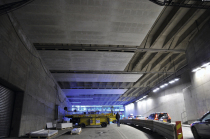
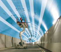
Under the prescribed circumstances and requirements the application of a layer of mortar Meyco® Fireshield 1350 was chosen. The minimum thickness (31 mm) was defined by the product distributor (BASF Construction Chemicals) on the base of the fire protection requirements. The fire protection layer was applied on the concrete lining in both tunnel sections (Fig. 7). Under consideration of the applying tolerance in layer thickness of ±4 mm a standard thickness of 35 mm was defined (the effective layer thickness is variable between 31 and 39 mm).
To extend warranty of the high requirements in tensile bond strength of fire protection layer with the existing lining a fully bond solution combined with stainless mesh reinforcement was chosen. The existing surface of the cut- and-cover section was pre-treated via robotic hydromilling (2000 bar) of the concrete surface to ensure full bonding of the fire protection mortar to the substrate. A minimal depth of roughness of 5 mm was prescribed (Fig. 8).
A stainless fine-meshed mesh reinforcement (with a diameter of 1.5 mm each 5 cm in both directions) was installed on the structure substrate with minimum 5 pieces/m2 stainless bolts to provide additional safety against delamination. After this, the fire protection mortar was applied in 1 step with a sprayed concrete robot. A total area of about 13 500 m2 of the mortar was spray-applied in the Bodio Part Section of the Gotthard Base Tunnel. Fig. 9 shows the detail of the fire protection layer construction.
For fixing stainless steel reinforcement matting to the inside walls of the tunnel a new spacer (mesh holder) developed by Fischer has been used in combination with the Fischer Nail Anchor FNA II 6x30/20 A4 (Fig. 10). This new spacer system has been tested according to the RWS fire curve. The coloured markings show the user the necessary minimum thickness of the mortar layer to be sprayed over the matting.
Conclusion
The amount of European transport tunnels in daily use without any form of fire protection is of concern. Of course, following risk assessments a great majority of these tunnels may not need fire protection, but certainly under the new requirements of the European Directive No.2004/54, and perceived new directives there are many tunnels that will require retrofit fire protection systems to be installed.
Very thin spray applied thermal barriers (less than 45 mm) will be required for many of these tunnels if clashes with the operational envelopes are to be prevented. The use of polypropylene fibre modified concrete is not considered an option for many existing tunnels due to the limited operating space. However, consideration may be given to sprayed concrete with polypropylene fibres if the space profile permits a minimum layer thickness of approx. 80 mm (Fig. 11).
It should also be noted that the general trend in increasing vehicle and train sizes and also increasing the tolerance to the structural lining to avoid clashes (at higher line speeds for example) puts additional pressure on the industry to develop very thin fire protection solutions.
In order to determine which system is appropriate for specific tunnels, consideration of the risk of structural collapse of the tunnel linings, and the effect it will have on 3rd parties is required.
In the case of existing tunnels, passive fire protection, in the form of thermal barriers, applied to the existing structure seems to be the only solution. A final consideration stems form the fact that nowadays all structures, for durability reasons, will need to be designed with concrete that has lower water/cement ratios (therefore very low porosity). This, from the fire behavioural side, does not represent a good solution because structure is very dense and compact and therefore, does not permit the water vapour to release the pressure. In this case, to ensure the durability of the structure from all points, (chemical and thermal attacks), it is necessary to utilize a concrete with low w/c ratio and a thermal barrier.
An example of this application can be found in TBM tunnels: the precasted segmental lining have high densities and therefore low permeability, therefore are very vulnerable to spalling.
References
– AlpTransit Gotthard AG
– Engineering Joint-Venture Gotthard Base Tunnel South (Lombardi Engineering Limited, CH / Amberg Engineering Limited, CH / Pöyry Infra Limited, CH).
– Fischer Fixing Systems
– Walo Bertschinger AG
– ITA (2004). “Guidelines For Structural Fire Resistance For Road Tunnels”. Working Group 6 Report. Published by the International Tunnelling Association, 2004.
– Khoury, G.A. (2003). “EU Tunnel Fire Safety Action”. Tunnels and Tunnelling International. February 2005. pp 20-23.
– Khoury, G.A. (2005). ”EU Tunnel Safety Update”. Tunnels and Tunnelling International. February 2005. pp 41-43.
– Khoury, G.A. (2005). Personal written communications on SafeT findings and concrete strength change on elevated temperatures – research work undertaken by Imperial College, London.
– Shuttleworth, P. (2002). Technical Paper – “Fire protection of concrete tunnel linings”. Written communication based on Rail Link Engineering tests for Channel Tunnel rail Link, UK.