Injections to restrict ingressing Water in Rock containing Anhydrite
 Quelle/credit: WBI
 Quelle/credit: WBI
 Quelle/credit: WBI
 Quelle/credit: WBI
 Quelle/credit: WBI
 Quelle/credit: WBI
 Quelle/credit: WBI
 Quelle/credit: WBI
 Quelle/credit: WBI
 Quelle/credit: WBI
 Quelle/credit: WBI
 Quelle/credit: WBI
 Quelle/credit: WBI
 Quelle/credit: WBI
More than 15 km of the tunnels for the Stuttgart–Ulm rail project located in the Stuttgart urban area lie in gypsum keuper containing anhydrite, which swells in contact with water. Owing to the swelling pressures that occur and the displacements caused by swelling, major damage has resulted in the case of many tunnels in the past. As a consequence, the corresponding sections of the tunnels in the Stuttgart urban area are driven absolutely dry.
The water-bearing leaching front is sealed by means of drilling in advance of the excavation by grouting polyurethane so that no groundwater can come into contact with the anhydrite-bearing rock. For the same reason the longitudinal path of water is hindered from passing through the loosening zone surrounding the tunnel with the aid of waterproofing wall structures. Around these waterproofing wall structures the rock is sealed using acrylate gels injections via radial drilling. In addition, the loosening zone resulting from the excavation in the proximity of the tunnel in anhydrite-bearing tunnel sections is sealed area by area using acrylate gel injections.
This article examines the results of a grouting test, which was carried out in the Feuerbach Tunnel; in addition ongoing acrylate gel injections in the Cannstatt Tunnel are dealt with.
1 Project
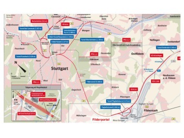
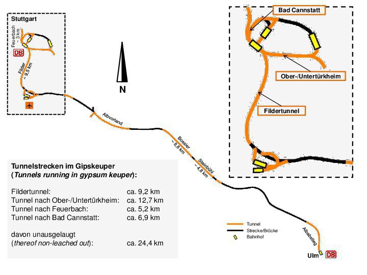
The route of the Stuttgart–Ulm rail project (Fig. 1) leads from the new Central Station via the 9.5 km long Filder Tunnel on to the Filder plain, from which it runs via the Albaufstieg tunnels (Boßler and Steinbühl Tunnels) on to the Swabian Alb and then through the Albabstieg Tunnel to Ulm Central Station. Each of the tunnels consists of two single-track tubes. The Airport is linked to the high-speed line by means of the Airport Tunnel, and the connection to Zurich via the so-called Airport Curve (Flughafenkurve).
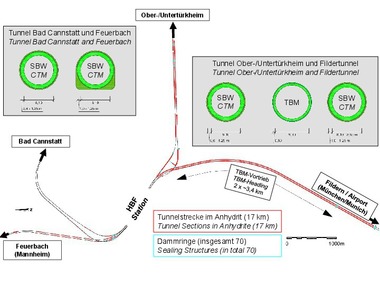
The new Stuttgart Central Station is connected to the high-speed route from Mannheim to Stuttgart via two single-track tunnel tubes leading to Stuttgart Feuerbach. The existing line through the Neckar Valley is linked up with the new Central Station via the tunnels to Bad Canstatt and Ober/Untertürkheim (Fig. 1, excerpt).
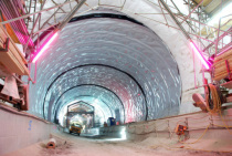
The central section of the two Filder Tunnel tubes is driven by means of a TBM. The other sections of this tunnel are excavated by conventional means like all the other tunnels in the Stuttgart urban area.
2 Subsoil
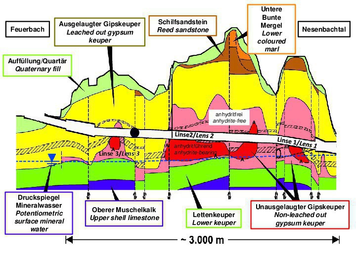
A geological longitudinal section for the tunnel leading to Feuerbach is displayed in Fig. 2. It reveals that the tunnel tubes are located entirely in layers of gypsum keuper. Lower keuper and upper shell limestone are to be found below the gypsum keuper. Above the gypsum keuper, reed sandstone and lower coloured marl were located in certain sections within the scope of preliminary tests.
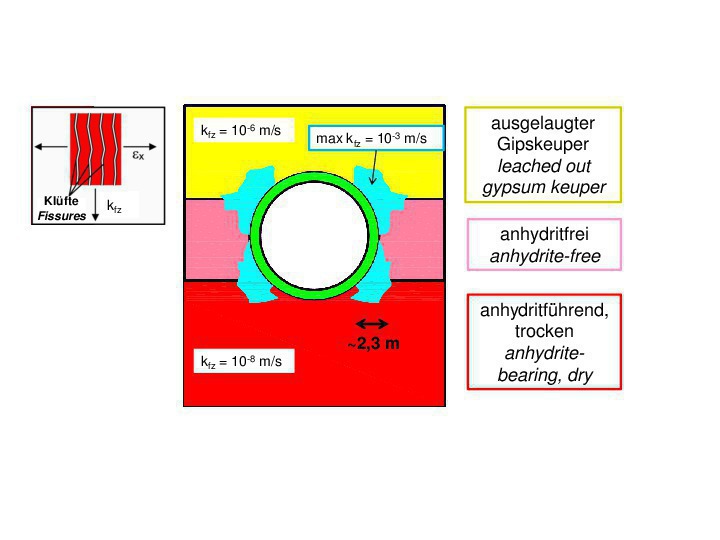
The gypsum keuper occurs in three forms, attributable to the sulphate content of the clay siltstones of this formation. The layers shown in red in Figs. 2 + 3 contain sulphate in the form of anhydrite. This dissolves in contact with water and recrystallises immediately as gypsum unless the solution is removed by the groundwater; in nature this process occurs in geological periods.
Above, the sulphate content in the layers shown in pink consists of gypsum. This still relates to solid rock, which, however, is no longer swellable. At the surface of this layer, the so-called leaching front, the gypsum dissolves upon contact with water and is removed with the groundwater. The leached gypsum shown in yellow remains – what is known as residual rock (see Figs. 2 + 3). This layer possesses soft ground properties. It behaves like silt with respect to water permeability and like gravel sand with regard to its deformability.
The transformation from anhydrite to gypsum is also quickly triggered during tunnelling unless major loosening is avoided and the groundwater or industrial water is kept apart from anhydrite-bearing rock. This process is associated with major increases in volume, commonly known as swelling. If one prevents or obstructs such deformations caused by swelling, large swelling pressures ensue [1]. This has resulted in damage being caused to many tunnels as well as heaving, which can extent to the surface of the terrain even in the case of deep-lying tunnels [2], [3].
Anhydrite-bearing gypsum keuper is encountered in three areas in the tunnel to Feuerbach; the so-called lenses 1 to 3 (please see Fig. 2). The tunnels leading to Bad Canstatt penetrate lenses 1 and 2.
3 Sealing Measures
3.1 Sealing the Leaching Front in Advance
The design concept for the Stuttgart 21 project`s tunnels is based on the fact that ingressing water must be minimised during and following construction. The production of the tunnels in the anhydrite-bearing layers is thus executed in an absolutely dry manner. Dry drilling, blasting and mucking are associated with pronounced dust development calling for extensive dedusting measures [4].
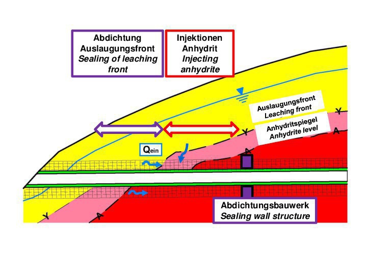
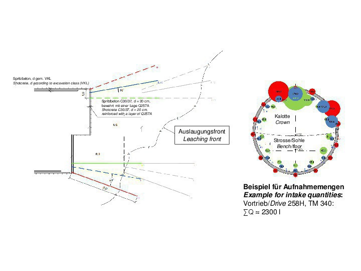
Furthermore, ingressing water from the groundwater must be prevented. The risk that seepage water comes into contact with the anhydrite-bearing rock exists primarily in sections of tunnel in which the water-bearing leaching front has to be penetrated or is located in the immediate surroundings of the tunnel (see Fig. 3). Advance injections with polyurethane to seal the leaching front are carried out successfully in these areas. In the process, generally very high intake quantities via drill holes result, by means of which the extremely permeable leaching front is penetrated (Fig. 4).
3.2 Injections in anhydrite-bearing Rock
A further flow path, by means of which the groundwater can access the anhydrite-bearing rock after construction, is the loosening zone resulting from the drive, which forms owing to blasting and the redistribution of forces in the rock after the excavation. The shear and tensile stresses resulting from the redistribution of forces, above all affecting the vertical fissures, extend up to several metres into the rock bordering the tunnel depending on the prevailing layer sequence (Fig. 3 and Fig. 5) [5], [6].
In this connection, even enlarging the opening width of the division planes slightly by only a few fractions of a mm results in increasing the water permeability by the range of powers of ten [1]. In order to avoid such loosening next to the “lower part” of the tunnel cross-section, the so-called U-profile was developed. In this case in contrast to the circular excavated cross-section, loosening of the rock caused by force redistributions only occurs in the roof zone [7].
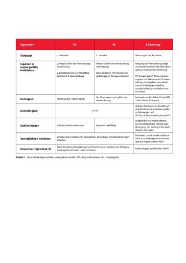
The areas loosened as a result of the excavation are subsequently sealed (see “Injecting Anhydrite”, Fig. 3). Acrylate gel is applied for these injections (Section 4 provides further details in this respect). Acrylate gel is a grouting agent that penetrates the finest pores on account of its viscosity and by means of which extremely low water permeability values can be attained [8], [9], [10].
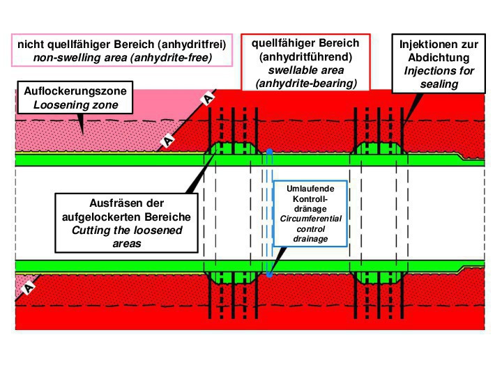
3.3 Sealing Wall Structures
In addition to the anhydrite injections, sealing wall structures (Fig. 6)
are produced to prevent water passing through the transition area between the gypsum-bearing and anhydrite-bearing rock. Towards this end, the rock is hollowed out up to a depth of roughly 1 m and replaced by steel fibre shotcrete via a 5 m long tunnel section – or via two 5 m long tunnel sections lying alongside one another – depending on the prevailing conditions. Subsequently the rock located outside the ring of concrete is sealed by means of acrylate gel via radial drill holes. A circulating control drainage system on the “dry side” of the first sealing ring serves to determine the success of the injections.
4 Injecting Anhydrite
4.1 Choice of Grouting Agent
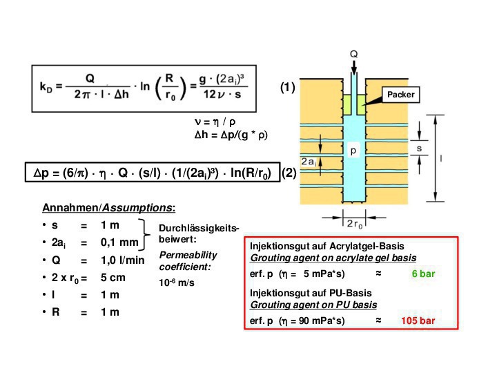
Fig. 7 displays the setup of a water permeability test or Lugeon test in a rock with a horizontal interface with a division plane gap s and a constant opening width of the division plane of 2ai. The drill hole diameter is indicated with 2r0 and a quantity of water Q is injected into a grouting section with a length of I with the pressure p. The permeability coefficient of the division planes or the rock kD can be obtained in accordance with [1] depending on the opening width (2ai) and the distance (s) of the division planes as well as the kinematic viscosity of the water (Fig. 7, equation 1).
The water pressures (p) measured in the Lugeon test and the grouted quantity (Q) enable the permeability coefficient kD to be determined by technical means. If this equation is resolved for the grouting pressure p and the dynamic viscosity of the water is replaced by the corresponding value of another Newtonian liquid this results in equation 2 (Fig. 7). This equation then enables the grouting pressure to be obtained, which is required to inject a grouting agent with Newtonian flow behaviour over a range R.
In Fig. 7 this was executed for a rock with a permeability coefficient of 10-6 m/s in a numerical example. It is shown that acrylate gel with a viscosity of η = 5 mPa*s (corresponding to five times the viscosity of the water) with a pressure of erf. p = 6 bar can be grouted over a range of 1 m. However, for grouting polyurethane in a corresponding fashion a grouting pressure of 105 bar is needed. However, that pressure would lead to the undesired “fracking” of the rock.
As rock with low water permeability must also be sealed by injecting anhydrite this means that only acrylate gel can be applied as the grouting agent in this particular case. Other chemical grouting agents with low viscosity cannot be contemplated for environmental technical reasons.
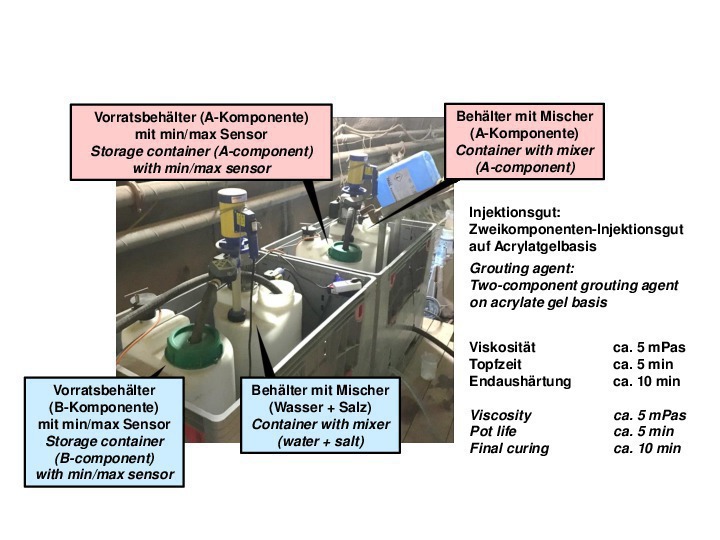
4.2 Grouting Technology
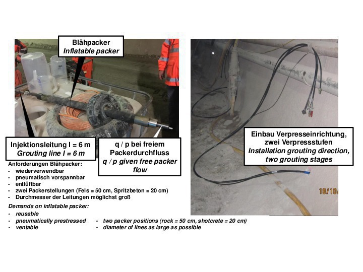
The acrylate gel that is applied comprises the components A and B, which are fed via a twin-piston pump to a static mixer and then injected into the rock via a delivery line and the drill hole (Figs. 8–10). The grouting section in the drill hole is closed off by means of a vented packer. The flow is measured by magnetic-inductive means and controlled by stroke counting at the twin-piston pump (Fig. 8).
The grouting pressure is measured behind the static mixer and prior to accessing the drill hole (Figs. 8–10). Pressure losses in the delivery line and the packer must be kept low and are measured in separate preliminary tests on the open system (Figs. 8 to 10).
In the test referred to in Section 4.3 an acrylate gel with a 5 minute pot life, after which the gel starts forming, was applied. After 10 minutes it was completely cured. For the sealing injections an acrylate gel with a pot life of up to 30 minutes is foreseen.
4.3 Injection Trial Feuerbach
Prior to commencing the grouting operations in the Feuerbach Tunnel a grouting test was undertaken at lens 3 of the tunnel (see Fig. 2). The test served to try out the injection technology, determine the necessary gaps and depths for the drill holes as well as to establish the required grouting pressures and quantities.
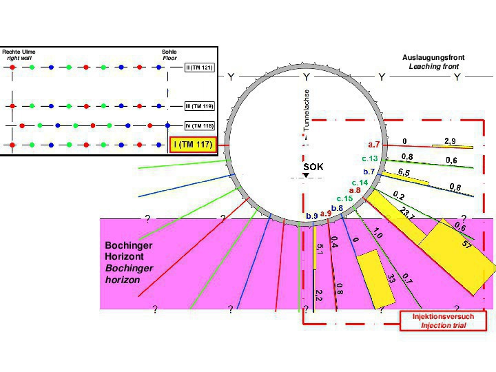
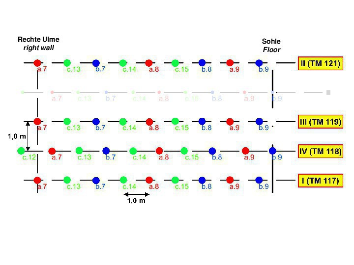
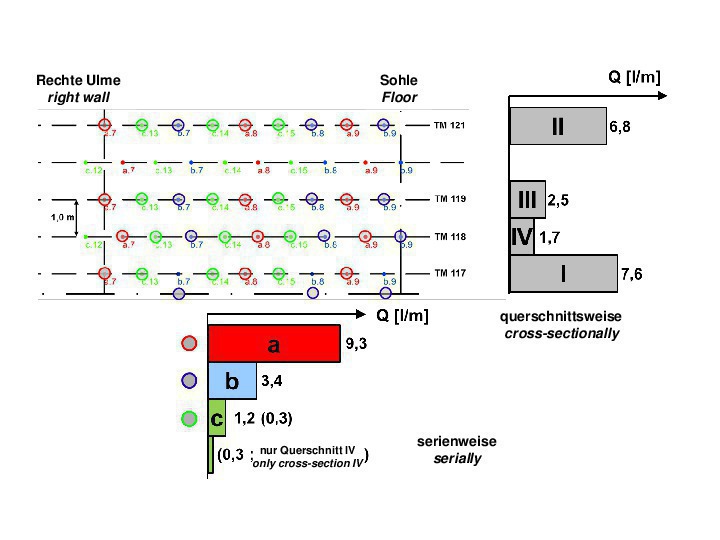
Where the test field is located the tunnel lies in dark-red marl. At roof level there is leached gypsum keuper (Y-Y in Fig. 11). The Bochinger Horizon, which is far more permeable, is to be found beneath the floor. Here the intention is to seal the rock laterally and below the tunnel. The test field extends over half of the area to be grouted, to the right of the tunnel axis (Fig. 11) and over four cross-sections with a total of 37 drill holes, with a gap of 1 m for the application points within a ring (Figs. 11 and 12). The lengths of the drill holes vary from 6 to 10 m, the drill hole diameter is 51 mm. The gaps between the four cross-sections, which were grouted in the sequence I to IV, amount to 1 m or 2 m between cross-sections II and III.
The injections were executed in accordance with the so-called back-step method in three series a to c. In the process, the gap between the application points for the drill holes was gradually reduced from 4 m (series a) to 1 m (series c) (Figs. 11 and 12). The maximum effective grouting pressure was selected at 5 bar. In Fig. 11 the quantities grouted into the rock in cross-section I for the two grouting sections for each drill hole are shown in litres per metre of hole length (l/m). It can be seen that the greatest amounts were injected via the drill holes of series a and in the Bochinger Horizon. Furthermore it is evident that the grouted quantities decrease from the drill holes of series a to series c.
Fig. 13 displays the average intake quantities shown individually for cross-sections I to IV. It can be seen that the amounts decrease from cross-sections I and II, which were grouted first, by way of cross-section III in between to cross-section IV, the last to be grouted. It can be discerned as well from the presentation of the average grouted quantities from each series also shown in Fig. 13 that the amounts accepted by the rock substantially decrease from series a to series c as well. The intake quantities accepted by series c in cross-section IV, which was grouted last, are the smallest. Thus the chosen procedure in keeping with the back-step method was a success.
4.4 Injections Bad Cannstatt
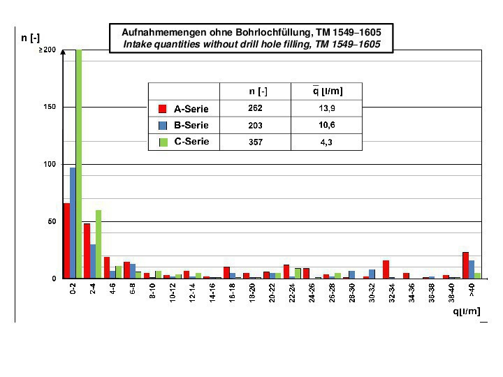
Currently the “Injecting Anhydrite” process is ongoing in excavation 3B for the tunnels to Bad Cannstatt, which has already been driven. The acrylate gel injections were carried out here in the same manner as described for the tunnel leading to Feuerbach. As an example, in Fig. 14 the quantities grouted in the section tunnel metre 1549 to 1605 for series a, b and c are shown in the form of a histogram. Here too, it is evident that the grouted amount clearly decreases from series to series. However, here the quantity accommodated by the rock is greater than in the test field for the tunnel to Feuerbach.