Rehabilitation of a Deteriorated Metro Line with Injection Technology
 Credit/Quelle: TPH
 Credit/Quelle: TPH
 Credit/Quelle: TPH
 Credit/Quelle: TPH
 Credit/Quelle: TPH
 Credit/Quelle: TPH
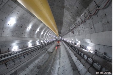
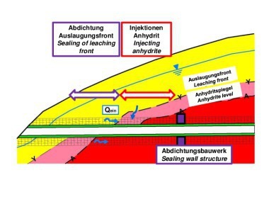
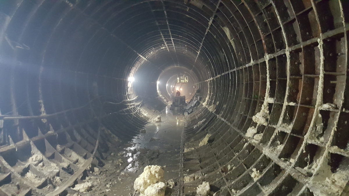
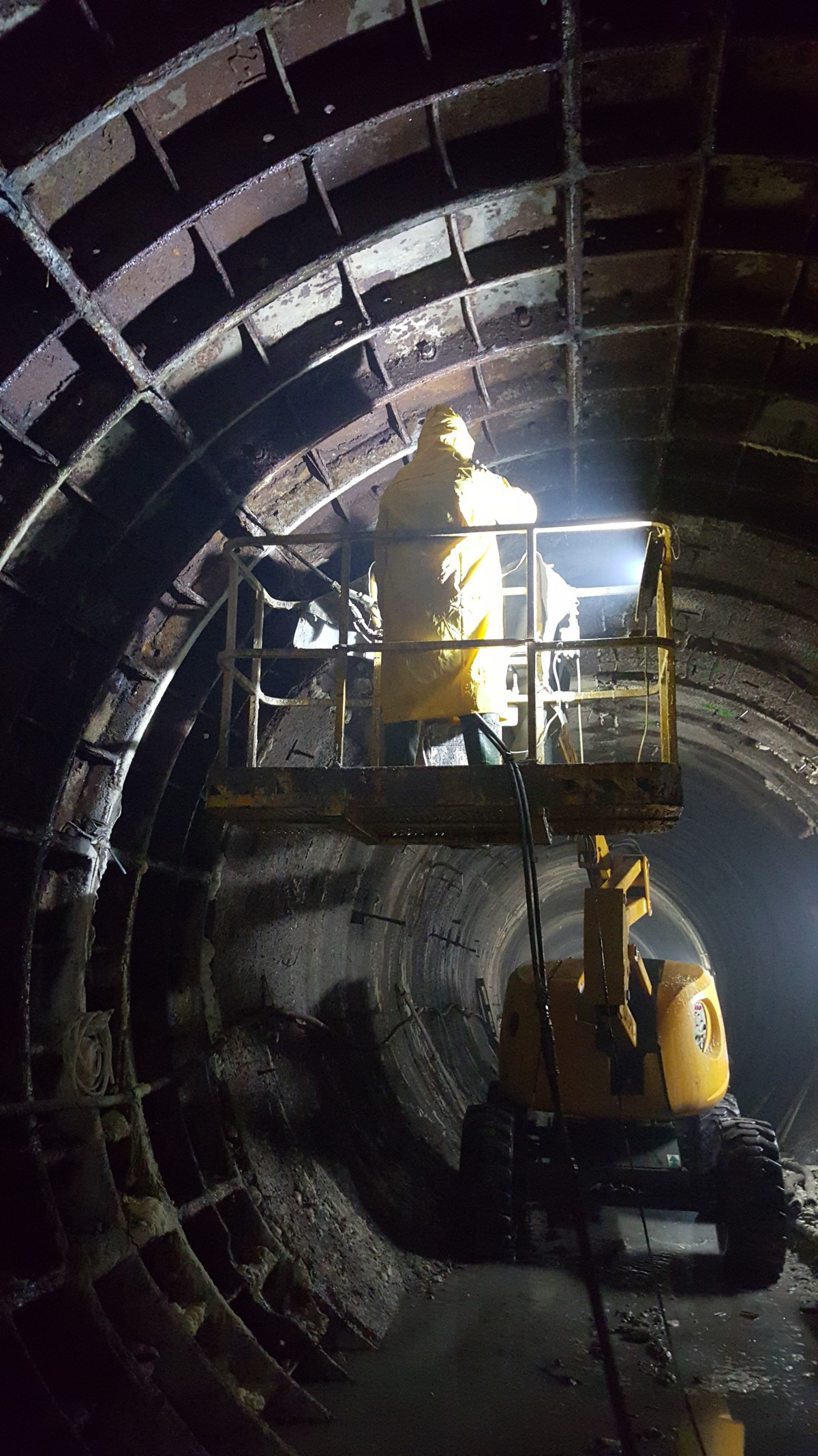
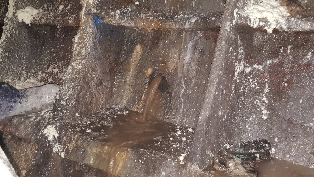
The article describes the technical solutions and methodology applied to stop the heavy water ingresses in the tunnels of a Metro Line, which have been left incomplete and abandoned since several decades with the natural corrosion and the consequent progressive decay of the tunnels. The waterproofing work was completed successfully over the whole length of 4,8 km by applying compartment injections followed by curtain injections behind the existing lining made either out of cast steel or reinforced concrete segments. In addition to filling the gaps, the extensive curtain injection and, where needed, crack injections guarantee protection from further water ingress. A new inner lining made of waterproof concrete would have been the only feasible alternative to applying the injection method – an expensive and time-consuming measure, which would have furthermore significantly diminished the tunnel’s cross-section.
1 Compartment Barriers and
Curtain Injections
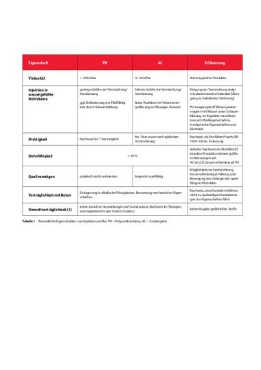
1.1 Resins and Equipment
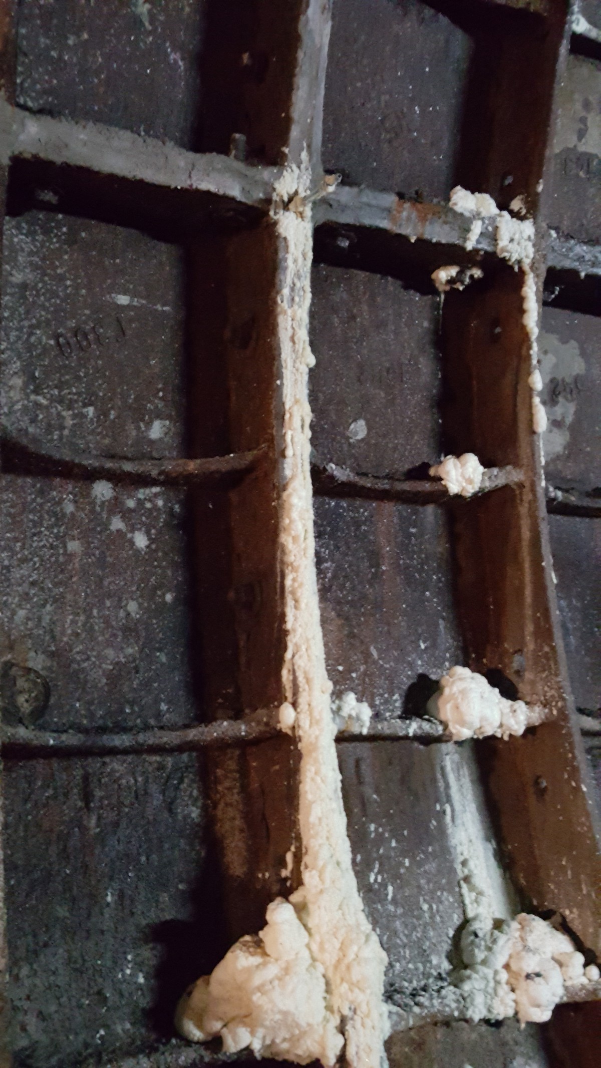
● Foam Seal is a dual component, quick reacting, slightly flexible silicate-based injection foam. It is used mostly for safe cavity filling but also for rock consolidation as well as for stopping water ingress in tunnelling, mining and civil engineering works. The homogeneous mixing of the two components results in a viscous emulsion, which does not absorb any water from its surroundings but instead, due to its high density, has the ability to push out the water.
● Pur-O-Stop HF is a dual component, urethane based foaming resin, it is fast reacting with rapid foaming action, independent of the moisture conditions in the soil formation or in the construction.
● PCC Mortars and cementitious grouts were used to respectively patch repair heavy damaged concrete segments and fill large gaps with no flowing water.
● A pneumatic, dual component injection pump was chosen instead of an electric one, this due to the necessity of having a reliable, steady flow of material during the work while maintaining mobility and ease of work in extreme conditions.
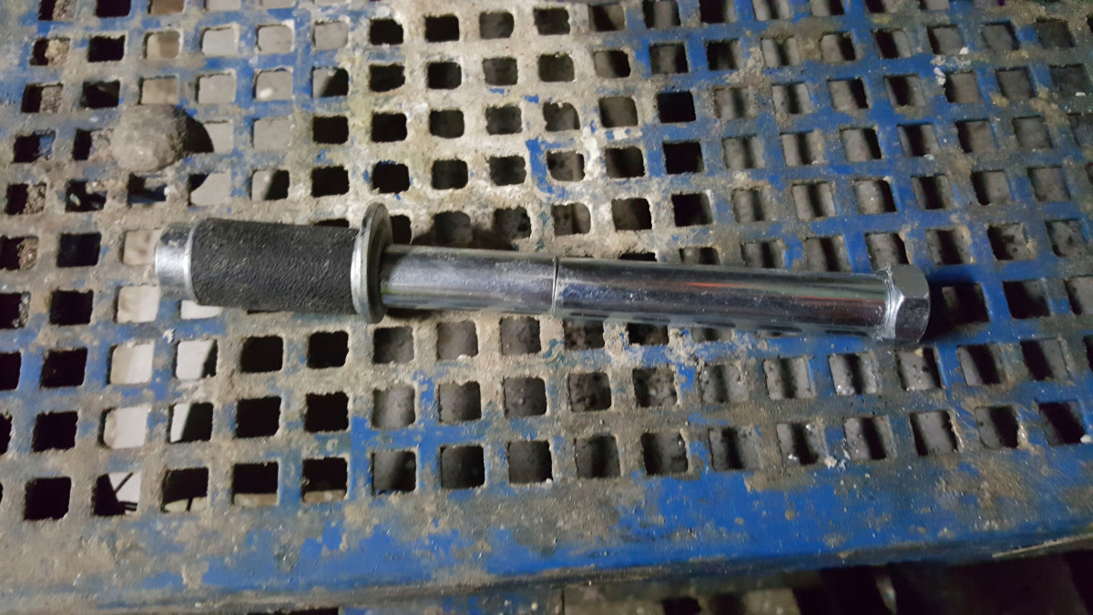
● 20 mm and 30 mm diameter steel packers were inserted into the boreholes to convey the injection materials. These packers are equipped with a rubber sleeve and were fastened manually to allow proper compression of the sleeve and pressure-tightness against the walls of the borehole. More recently, injection needle-like injection packers are available as an alternative to steel packers for the rehabilitation of segment linings.
1.2 Break of Longitudinal Water
Conductivity; Curtain Injection
of the Segments
To stop the water flow behind the segment lining, the procedure followed a two-step approach. At first, annular resin barriers were created behind the segments at 10 m intervals followed by curtain injections to stop the remaining water ingress between the barriers.
Resin Barriers
To stop or break the longitudinal water flow in the gap between the lining and the ground, rings of expansive resin (Foam Seal or Pur-O-Stop HF) were created by placing 20 mm boreholes in radial disposition on a defined section with 50 cm spacing.
Injection then proceeded bottom to top and alternating left and right sides to keep the level of the injected resin even. A steel packer was placed in the lower hole and coupled with the injection head. The injection proceeded until the resin appeared from the borehole immediately above.
To overcome increase of water pressure during injection, segment plugs were left open. In some areas, were pressure was excessive, the rings were placed at closer distance, typically every 4 to 5 segment rings. The reduced distance between two resin barriers greatly simplified the following curtain injections within the newly created compartments in between rings.
In Brief: Curtain Injections
Once two rings were completed and the compartment was built, a series of radial holes were drilled and injected with a thixotropic cement grout (water, cement, fine sand and thixotropizing admixture) to prevent it to flow out of the joints between the cast iron segment linings that had no sealing at all.
The cementicious grout injection procedure was performed to create the best possible conditions for completely filling the gaps, which were either void or filled with water. Sealing waterways around the tunnel generally started with sealing the points of major water ingress first. Once these were plugged or filled with grout, the waterproofing works proceeded at the smaller leaks. The first injections often caused new leaks in other segments which had to be taken care of consecutively. The process was repeated until it the whole compartment had been completely injected with cementitious grouts.
Complementary Works
Nevertheless, even with the compartmentation and systematic curtain injection, in several parts the cement grout, in spite of its thixotropy and resin barriers, was either washed out or not completely waterproof. In these cases, further complementary resin injections for gap or crack sealing were performed to ensure 100 % tightness of the old tunnel.
2 Backfilling (Curtain Injections)
2.1 Equipment and Material
The backfilling behind the segment lining was made with grout mortar and cement grout via a spiral pump with mixer. Grout injections were performed at all stages with a water-cement ratio of 0.4 including superplasticizer and thixotropizer mix to ensure the ideal creamlike consistency of the cement mix.
If the theoretical injection volume was reached with no significant increase in pressure (<1 bar) a second phase grout with a higher w/c ratio (0,7) was later applied, until the maximum design pressure of 3 bar had been reached.
2.2 Execution
To allow a complete filling, boreholes of 30 mm were drilled in the lining to reach the gap behind. The holes were distributed in radial fashion every 2–3 m, roughly at 12, 2, 4, 6, 8 and 10 o’clock positions and the grouting procedure also followed a bottom to top approach, with alternating injections on the left and right sides.
When the grout showed up in the injection ports located directly above, the injection was discontinued and moved to the successive port to allow the complete gap filling around the entire section perimeter of the compartment.
Eventual leakages of cementitious grout through the (untight) joints of the cast iron segments caused work suspension to seal these either with “low-tech” media like rags or wooden wedges or some more “high-tech” measures like quick-setting mortar plugs or even chemical grouting with Pur-O-Stop HF or Foam Seal, via 20 mm holes drilled nearby the leakage. (The product choice here depended on several factors like size of the leak/cavity, intensity of the loss and last, but not least, personal preference of the foreman. It is important to note that in this particular case the goal was to achieve a temporary block of the flow of grout to complete the curtain injection of the gap behind.)
Once the leakage point was sealed, the injection of cementitious grout resumed. These operations were carried out systematically at each compartment.
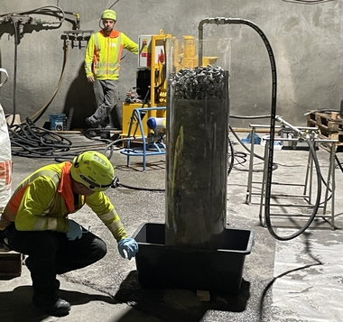
2.3 Preparation and Injection
of the Mixes
The cement grout was prepared at the station platform, at first directly nearby the working area. With the advance out of the station into the tunnel, the mix, prepared in a high-speed colloidal mixer with a mixing duration of 30–60 seconds was subsequently poured into a mixing tank, that kept it moving until it could be pumped by the grout pump to an appropriate distance to the injection area. The dimensions of the hoses were 1/2” for the resins and 3/4” for cement grout. Excess grout was transported back to the mixing tank via a return line.
2.4 Monitoring of the Injection Works
The flow rate, volume and pressure of the injected mix, during each injection stage and in all the boreholes, were recorded automatically and digitally. Monitoring also included recording any connection between boreholes and inflows through the lining.
During and after grouting the contractor carried out visual inspections and convergence measurements in tunnel sections of 20 m length to detect possible deformations of the lining.
The hydrogeological environment and water inflows into the tunnels were also monitored by the contractor, by measuring the groundwater level of the surrounding subsoil with piezometers installed in the boreholes at an adequate distance from injection points to prevent the measurements from being affected by grouting. Furthermore, variations in water inflow rates were measured using gauges in open channels or closed conduits in diverse tunnel sections.
2.5 Criteria for Stopping the
Grouting Operation
● Grouting into a borehole was stopped when the following conditions applied:
● Maximum pressure of 3 bar at the borehole mouth for 5 minutes, with a maximum flow rate, 2,5 l/min for cement grout and 1,5 l/min for polyurethane two-component resins
● Maximum volume of 1 m3 for each stage of grouting into a borehole
● Minimum flow of 2,5 l/min and 1,5 l/min respectively for each type of mix, but without reaching the maximum pressure established
● Displacement of the segments of 3 mm
In those boreholes where the pressure of infiltrated water was measured, additional 3 bar were added to the value obtained in order to establish an effective counter pressure and push the grout/resin into the gap/crack, compensating the inflow water pressure.
2.6 Completion of Borehole Grouting
The grouting operation was considered completed for a specific compartment, once injections into the upper borehole at the 12 o’clock position reached the maximum design pressure of 3 bar.
3 Complementary Works (Residual Gaps and Crack Injections)
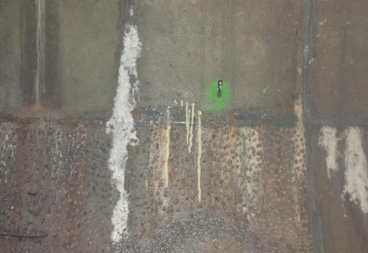
After the segment resin rings and the curtain injection (back filling) of the compartments were fully finished, some places that seemed dry after the grouting works showed renewed water infiltrations, even several days after. Actually, these water infiltrations were signs that the work was effective, because they appeared due to the return of ground water level to its original position.
For those areas that still showed water infiltrations to a greater or lesser extent, 20 mm diameter boreholes were drilled for chemical grouting to definitively stop the leakages. The minimum borehole length equaled the lining thickness plus 0.3 m to penetrate at least 0.2 m into the ground around the tunnel (the gap between the segment lining and the rock measured between 0.1 and 0.2 m).
To be on the safe side, additional injection holes were drilled along the resin segment ring barriers that defined the backfill compartments, to perform a secondary resin injection. These injection holes were either left unplugged or equipped with packers with valves left open. When a significant amount of water inflow appeared, the valves were closed in the relevant areas, subsequently injected with chemical grouting and sealed, even with high water pressure and high flow.
When too much localized water flow occurred, the leaks were either temporarily closed with a conical plastic or wood plug to gain time for the grout material to completely react within the cavities. If the water flow carried solids (e.g. sand or gravel), it was extremely important to prevent this as quickly as possible, either with “low-tech” (rags, wooden wedges etc.) or “high-tech” products (geotextiles, plastic plugs etc.).
4 Final Considerations
This project shows a few interesting insights: A large underground construction, a metro tunnel in a capital city, was in an advanced corrosion process after some 25 years of being left abandoned due to geopolitical problems. This shows us how transient our buildings can be if left alone and it consequently shows the importance of maintenance and prevention of water ingress inside the construction.
The combined application of chemical alternated to cementitious grouting was an optimum solution to merge the positive qualities of both materials optimizing costs and performance.
It is also true that a “purist” of chemical grouting may point out, correctly, that the resins used for the segment ring barriers are more suited for gap filling than for crack sealing. However, considering the jobsite conditions, location, distance from supply source and immediate availability, this not ideal choice turned out to be the best choice available for this project, combined with the applicator skills that were of paramount importance for the successful completion of the rehabilitation works.