Subsoil Freezing in a perfused Subsurface
In the following report a groundwater flow is described as the determining thermal influence for freezing measures in tunnelling. Early investigation and analytical consideration of the prevailing groundwater conditions are essential for reliable prognoses of the freezing times as well as safe and economic freezing concepts.
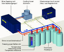
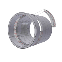
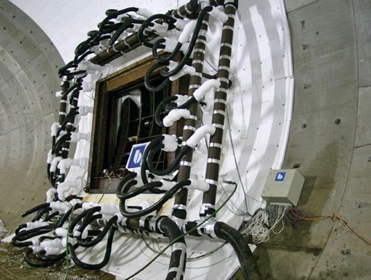
Artificial subsurface freezing for creating statically sustainable and watertight frost zones has proved itself on many occasions in the past as an accompanying measure in tunnelling and has actually gained in importance of late for a large number of projects. The driving of cross-passages for escapeways between neighbouring tunnel tubes (Fig. 1) in particular and the production of underground stations through expansion using mining means to follow upon mechanically driven tunnels represent interesting, topical and future-oriented sectors for the freezing method in tunnelling [8, 10]. In addition to purely technical advantages thanks to the broad spectrum of application for various types of soil, the method stands out compared with others when it comes to its environmental compatibility as it can be executed in such a way that it is reversible so that no negative residues remain behind in the soil or groundwater. However, frequently the scheduled application fails owing to the high energy costs for the removal of heat from the soil. Apart from the freezing process as such this can become even higher if further thermal influences resulting from additional installations and an increased energy outlay for the freezing plant have to be compensated for (Fig. 2).
Any reliable determining of the time required to freeze the desired frost zone must consider the quantities of heat, which govern the temperatures prevailing in the soil and which can substantially influence the progress of freezing. Compared to other thermal influences a freezing measure close to the surface (Fig. 2) allows a groundwater flow to be characterised as governing the freezing time and costs.
Even in the case of supposedly moderate groundwater flow velocities the convective heat input is considerable on account of the high thermal capacity of the water: a groundwater flow, which possesses a temperature of 13° C and flows at 1.0 m/d (discharge velocity), generates a heat flux density of approx. 630 W/m². This roughly corresponds to the sun’s heat flux density on the earth’s surface on a clear, sunny spring day on the Island of Sylt (600 W/m²). The peak values for solar rays at midday in summer in Germany amount to around 900 W/m². This heat input is arrived at by a groundwater flow of 1.5 m/d. As a consequence when the subsurface is strongly pervaded, the creation of frost can cease altogether should a thermal balance result between the induced quantity of heat and the one removed by the freezing pipes. The zone of frost is then unable to take over its desired function. High flow velocities exceeding the degree of natural flow can occur especially where there are buildings present as a result of jet effects or in interstratified coarse layers with high permeabilities.
1 Transmission of Heat and Transport of Water in the Soil
1.1 Physical Principles
The prevailing heat transfer mechanism in soils is the conduction of heat as such [5]. This transport of energy results from a drop in temperature and takes place through an atomic reciprocal effect between neighbouring molecules. The flow of heat Q [J/s or W] thus created is in this case proportional to the drop in temperature and the considered cross-sectional area. The proportionality factor is a material-specific, mostly temperature-dependent parameter and is described as thermal conductivity [W/(mK)] (Fourier’s Law). Other mechanisms such as for example thermal radiation do not play a decisive part given a high degree of saturation in stationary groundwater. The effect of forced convection must also be taken into consideration in the case of flowing groundwater. This describes a transfer of heat through a groundwater flow, which is caused by differences in potential or pumping processes. The quantity of heat transported as a result of flowing water largely depends on its temperature and filter velocity vf. The filter velocity vf of the convective term results from Darcy’s well-known law:
h
vf = kf · kf · i
l
Accordingly the flow velocity of the water is proportional to the hydraulic gradient i (Fig. 3). The permeability coefficient kf [m/s] depends on the flow properties of the fluid and the properties of the medium it flows through [6]. As the fluid’s properties – density and viscosity – depend on the temperature, the kf value in the temperature spectrum relevant for subsurface freezing is also by no means constant. Even in non-frozen state its magnitude fluctuates so greatly with the temperature that this change must not be neglected for a reliable evaluation of the flow.
In this way the temperature field influences the permeability coefficient on account of the temperature dependence of the water properties and in turn the filter velocity, which for its part is incorporated in the convection term for the heat transport equation. In other words, a completely coupled problem exists. Fig. 4 shows schematically the model inter-relationship.
1.2 Temperature Dependence of the Soil Characteristics
The temperature dependence of the thermal and hydraulic parameters must be taken into consideration for calculating freezing measures. This applies on the one hand for the temperature-related properties of the individual soil components – solid matter, water and ice – but particularly, however, their changing composition in terms of quantity in the course of the freezing process.
Fig. 5 shows as an example the qualitative course of the thermal characteristics thermal conductivity (T) and thermal capacity c (T) for a soil taking into account the change of phase for the pore water during freezing. Particularly striking is the rise in the thermal capacity in the freezing interval between solid (Ts) and liquid temperature (TL), which results from the release of latent heat L. This amounts to L = 333,600 J/kg for pure water and would thus suffice to increase the temperature of 1 kg of water (cs,w = 4.200 J/kgK) by almost 80° C. The released heat delays the freezing process and thus influences the freezing rate considerably. During the melting process on the other hand this amount of energy must be expended in order to break open the ice’s crystal structure. Only then does the temperature of the frozen ground change again. The inertia of frozen soils during the melting process can be attributed to this fact, which represents a safety factor for a construction project that should not be underestimated given short-term functional disturbances involving the freezing system. A rapid melting process does not occur.
The requirements on a solution model to describe frost spreading taking the flow of groundwater into consideration result from the previously mentioned inter-relationships. As a result time-related (non-stationary), non-linear (the thermal and hydraulic characteristics depend on the temperature) and completely coupled heat transport groundwater flow calculations have to be executed. Towards this end numerical methods are required. The results of freezing calculations provided in the following are based on a simplified phase change model that is suitable for practice, which sufficiently well describes the thermal and hydraulic behaviour of a freezing soil for the freezing process in tunnelling. Far more decisive for eliminating uncertainties in conjunction with a prognosis for the freezing process is accurately describing the flow velocity and direction for the groundwater [2].
2 Simplified Phase Change Model
The starting parameters required for a numerical simulation of freezing can be reduced in a large number of cases to known standard magnitudes such as density, grain distribution etc., which are determined in any case within the scope of normal geotechnical investigations. The transference of geotechnical parameters to thermal technical values succeeds because the thermal characteristic values such as thermal conductivity and thermal capacity, permeability and the freezing behaviour of a water-saturated, non-cohesive soil can be derived from them with adequate simple mathematical/physical models with sufficient accuracy [7]. For this purpose only the volumetric proportions of solid matter, water and ice for each temperature have to be known if the theory of continuity is taken as the basis [4]. The main cause for the behaviour of the soil’s temperature dependence is attributable to the changing division of the proportion of pores n in the ice and water phases, ni und nw, in frozen state (Fig. 6).
At the core of the solution model the reduction of the water content nw falling short of the freezing temperature is expressed by a freezing function , which can assume theoretical values between zero (completely frozen) and one (unfrozen) describing the distribution mathematically as follows:
nw = n · with 0 ≤ ≤ 1
The increasing proportion of ice is consequently obtained as a complimentary value given complete saturation:
ni = n – nw
The precise course of the freezing function depends on the soil. However, it is shown that the description of the course of is possible on the basis of the unfrozen water content wu, as not all water is frozen even given temperatures below the freezing point. The ongoing value of wu represents a direct indicator of the course of freezing and can be derived with sufficient accuracy via the specific surface from the soil’s grain distribution. Special tests in the frost lab are thus not necessary.
Through the implementation of this phase change module (“freezing module”) the existing finite differences programme SHEMAT (Simulator for Heat and Mass Transport [3]) was extended for application in the field of freezing measures close to the surface and used for deriving recommendations for optimising freezing for a cross-passage subject to the influence of flow [2]. A number of recognitions are presented in the following.
3 Influence of a Groundwater Flow
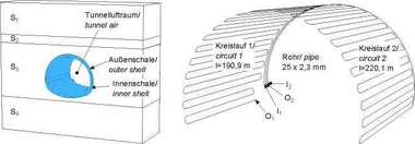
As an example the freezing process of a circular, symmetric frost zone subjected to a horizontal influence of flow close to the surface is examined. The selected dimensions are geared towards a typical cross-passage freezing process. The clear inner diameter of the excavated profile is set at 5.50 m and the statically required frost zone thickness 1.50 m. In the so-called basic system, which serves as a reference case, 18 freezing pipes are distributed evenly over the perimeter set at gaps of roughly 1.22 m apart. Only one half of the tunnel need to be considered for symmetric reasons (Fig. 7). In order to investigate the influence of a groundwater flow on the freezing process its velocity is increased successively in the simulations. As a result a spectrum of 0.25 to 1.50 m/d for the discharge velocity is covered. In the case of greater velocities the growth of the frost zone ceases at critical points so that a complete frost zone cannot be attained. The urgent necessity to include the groundwater situation that is actually prevailing at the planning stage becomes especially evident, if the frost zone geometry is compared at the same time points but for varyingly large flow velocities. In Fig. 8 this is undertaken for the time point in the basic system at which the entire freezing process (t = 20 d) has already ceased in the case of no flow.
For the basic system as expected the intake side emerged as determining for the freezing time regardless of the flow velocity. Fig. 9 displays the freezing times for all investigated flow velocities. It is shown that the freezing time for the basic system given increasing flow velocity increases first of all more or less linearly and then to a great extent exponentially. This application enables the critical velocity to be anticipated, at which the freezing time veers towards infinity for this soil, i.e. the frost zone can no longer be closed. An insufficient investigation of the flow velocity or even a lack of one or even only a rough estimate on the basis of an estimated kf – with fluctuation ranges amounting to a power of ten or more can thus lead to serious false estimates of the freezing time. A planning error, which has to be compensated for during execution that entails enormous difficulty. For instance the costs in the case of a flow velocity of 1 m/d compared with a rate of 0.5 m/d for the example displayed here rise by 46 %. An error in estimating the flow conditions of this magnitude is easily imaginable during the planning phase given a lack of proper investigation.
4 Modified Freezing Concept
The objective of optimised design variants must be to arrive at a levelling out of the frost progress in those areas that are affected by the flow to varying degrees. This can be achieved for instance from the installation side by the repositioning of the planned freezing pipes or the installation of additional ones or operationally by controlling groups of pipes as required [11, 1].
Even without the installation of additional freezing pipes the freezing time in the given example can be reduced by 20 % as a result of an arrangement adjusted to the flow.
This can e.g. be arrived at by concentrating the freezing pipes at the intake side or relocating the pipes from the central line into the intake area. A far greater effect can be attained by pre-cooling the groundwater through positioning additional pipes in the inflow. Thanks to this arrangement pre-cooling is particularly effective and at the same time a wedge-shaped frost zone is formed to divert the flow (Fig. 10). In this way the cross-passage is thus no longer exposed frontally to the flow in the intake area either. The freezing time is shortened considerably as a result. By employing no more than 4 additional freezing pipes the 50-day freezing period in the basic system can be halved to 25 in this case. Extremely uniform frost progress along the complete perimeter of the cross-section is attained. Seen from thermal aspects pre-cooling represents an extremely effective method. However, it must be looked into to find out whether this can actually be translated effectively into practice.
As only a part of the costs depends on the flow velocity, the reduction in freezing time does not exert the same effect on cost reduction. However, the optimisation example with pre-cooling in spite of the additionally installed freezing pipes reveals a possible savings potential of at least 20 %. At the same time freezing simulations make it clear that by intervening in the temperature field and altered flow paths the critical area is often only relocated without arriving at an overall reduction of the freezing time. As a result the system should always be considered in its entirety for assessing a variant reliably. The advantages of a certain design variant depend on the existing flow velocity and direction of flow. As a consequence it serves no purpose to provide an overall recommendation for optimising all conceivable flow velocities and frost zone geometries. The prerequisite for a project-related optimisation is always reliable investigation of the flow conditions, so that the critical areas of a system can be safely identified. It has to be found out whether a pronounced change in direction or even the complete reversal of the flow, for example as a result of situations brought on by flooding close to a river, can occur, as consequently the supposed advantages possessed by a system can quickly become a disadvantage for the overall situation [2].
From the investigations carried out so far at the Chair for Geotechnical Engineering at the RWTH Aachen University/D the following recommendations for shortening the freezing time or optimising the mode of operation for a freezing measure influenced by flow can be derived. They can serve to help arrive at an optimised system for the situation within the planning process:
– The flow velocity and direction represents the determining starting parameter in the calculations. The freezing time increases exponentially as the flow velocity increases.
– The flow velocity can most reliably be obtained from level measurements providing that the permeability is known. This should preferably be achieved by means of a pump test. Possible changes of the size or direction of flow during the course of the building project should definitely be taken into consideration during the planning phase. – In order to assure that optimisation succeeds the critical area determining the freezing time for the prevailing flow situation must be localised in advance. This is generally the intake area given an equidistant pipe set-up.
– Any compression of the distance between pipes in the intake area in order to attain a shorter closing time is preferable to compression in the output area. – It should always be established to what extent closure of the frost zone in the intake area exerts a negative effect on the transition area to the roof. Should this form a new critical area possibly giving arise to a through-flow the intended shortening of the freezing time is endangered. Early diversion of the flow via the roof is a favourable approach in this case.
– Pre-cooling of the groundwater turns out to be a very effective measure in order to shorten the freezing time. As a result is should be established to what extent the freezing pipes can be placed in such a way in the groundwater inflow that this additionally leads to a diversion of the flow once the frost zone has been established.
– The intermittent mode of operation can be optimised if the pipes are bundled together to form individual groups so that they can be controlled as required. There is a great savings potential especially in the output area by interrupting the freezing process from time to time.
In conclusion the Wayss & Freytag Ingenieurbau AG deserves the authors’ thanks for its financial support and providing construction site data within the scope of the research project carried out at the Chair for Geotechnical Engineering at the RWTH Aachen University/D. Our thanks also go to the SHEMAT development group headed by Professor Clauser for its active support.