Innovative Mixshield Explores the Underground for Munich’s 2nd Core Route
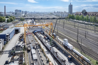
The first of a total of six tunnel boring machines for the construction of the 2nd core route in Munich began operations on September 17, 2026. The Mixshield from Herrenknecht AG, christened “Donna Maria,” is excavating the exploratory and rescue tunnel (ERS) for the western construction lot, from the launch shaft in front of the Donnersberger Bridge to the Marienhof Station, and is equipped with project-specific innovations.
 1 | The launch shaft für the mechanized excavation of the western lot of the 2nd core line in Munich
Credit/Quelle: Herrenknecht AG
The following article presents technical innovations such as the center flushing system with an exceptionally high flushing volume in the excavation chamber, the optimized segment logistics with longitudinal transport, and the high-capacity slurry circuit.
Project Description
The launch of the Mixshield for the western exploratory and rescue tunnel in mid-September 2026 (Fig. 1) has now marked another important milestone for one of Germany’s largest infrastructure projects. Under the direction of the project owner, DB InfraGO AG, the Mixshield manufactured by Herrenknecht AG is being operated by the ARGE Tunnel Hauptbahnhof (ATH) consortium, consisting of Wayss & Freytag Ingenieurbau AG, Max Bögl Group, Ed. Züblin AG, and Bauer Spezialtiefbau. On the one hand, the ERS replaces several very laborious rescue shafts along the approximately 11-kilometer-long parallel relief line running alongside the core line between Donnersberger Bridge and Ostbahnhof. On the other hand, it serves to investigate the heterogeneous ground of this construction section in Munich’s densely built-up city center, providing important insights into the ground conditions.
 Table 1 | Tunnelling parameters for the ERS
A total of six tunnel boring machines (TBMs) will excavate the route on the western and eastern construction lots over the next few years. The ERS and the two traffic tunnels will start in the west and east, respectively, and converge at Marienhof Station. The tunnelling route for the Mixshield, which has now begun operations, is approximately 3.2 km long, with a minimum curve radius of 250 m and gradients ranging from +1% to -7%. (Table 1).
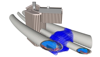
The machine passes under the Donnersberger Bridge and the wide track bed with minimal overburden, connects to Rescue Shaft 3 – which allows for maintenance work – is pulled through the main station, and finally emerges at a depth of more than 40 m at Marienhof Station. At Marienhof, the shield skin remains in the ground, while all other components – including the back-up system – are pulled back for subsequent disassembly.
Particular challenges arise from the initially shallow overburden of only about 4 m, the densely built-up inner-city areas, the heterogeneous ground conditions with cohesive soils, and the work being carried out below the groundwater table.
In addition to the high groundwater table, the ground is expected to consist of predominantly Tertiary clays and silts. Fine sands and Quaternary gravels are also present, although the Tertiary and Quaternary sediments may be partially consolidated. The overburden above the TBM ranges from 4 m to 40 m during tunnelling, with sections up to 35 m below the groundwater table.
Assembly Conditions
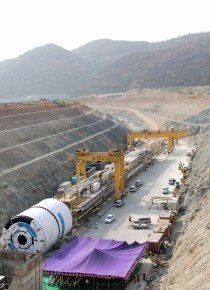
Conditions for assembling the TBM in the long launch shaft were nearly ideal. The machine, including all its gantries, was fully assembled, commissioned, and tested. The excavation pit had been partially backfilled up to the level of the ERS and prepared with a temporary floor slab and a concrete support structure. This included the bored pile wall with the visible openings for the three tunnels.
Mixshield Technology With Project-Specific Enhancements
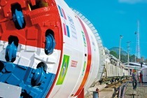
 2 | The Mixshield for the ERS at the Herrenknecht workshop, ready for acceptance by the ARGE Tunnel Hauptbahnhof
Credit/Quelle: Herrenknecht AG
 Table 2 | Parameters of the Mixshield for the ERS
Early in the project, the decision was made to use Mixshield technology for mechanized tunnelling (Fig. 2). It is designed to ensure safe and low-settlement tunnelling, given the settlement-sensitive track area at the main station, the densely built-up city center, and historic buildings such as the Frauenkirche. Together with the project managers from the contractor consortium ARGE Tunnel Hauptbahnhof, Herrenknecht AG specifically adapted the machine to the particular conditions of the project, which included high groundwater levels and varying ground conditions. A key requirement was to integrate a wide range of technically necessary solutions into a machine with a comparatively small diameter (Table 2).
Addition of Stopping Grain
The first challenge arises right at the start of the ERS due to the very shallow overburden of only 4 m in front of the Donnersberger Bridge and the sandy, gravelly ground beneath the track bed. To counteract suspension losses in cohesive ground, it is possible to feed stopping grain or other additives to the suspension through the feed line. A pump specifically designed for this purpose allows for very rapid feeding.
Optimized Flushing Concept
The Munich soil consists largely of cohesive soils with compact loam and clay. To prevent clogging, Herrenknecht optimized the flushing concept. The slurry circuit is designed for a very high flow rate – up to 800 m3 per hour – relative to the machine’s size. Additionally, recirculation with a flow rate of approximately 400 m3 per hour is possible, allowing excavated material to be extracted and returned to the excavation chamber. This results in a flow volume of up to 1200 m3 per hour in the area of the jaw crusher in front of the grid. This design of the circulation system required the Herrenknecht design department to create space for the installation of appropriately large-diameter DN300 pipes and high-performance pump systems.
Precise Pressure Control
Precise control of the support pressure is a standout feature of the mixshield technology developed by Herrenknecht in collaboration with Wayss & Freytag approximately 40 years ago. Support pressure control helps tunnelling crews to reliably reduce the risk of settlement. They are assisted in this by an automatic regulation of the compressed-air cushion in the excavation chamber. Herrenknecht took into account the high flow rates of the slurry circuit, with which the Mixshield for Munich is equipped, when designing the automatic support pressure control system. In addition, a unit for manual control by the machine operator is installed directly in the control cabin, allowing the operator to intervene quickly if necessary.
In addition to settlement control, the support pressure control system is also responsible for minimizing the impact of the machine’s advance on the groundwater. The goal is to ensure that neither the groundwater level nor the water quality is affected at any time.
Development of the Back-Up System
 3 | Interior view of the rescue container for 24 people
Credit/Quelle: Herrenknecht AG


 4-6 | The segments on the 80-m-long segment feeder are transported longitudinally. They are rotated transversely shortly before the erector picks them up
Credit/Quelle (3): Herrenknecht AG
The back-up system underwent targeted further development: The major challenge was optimizing the components given the specified clearance and the resulting internal diameter. Among other things, the system must accommodate the air supply duct, the escape and rescue routes, and the segment logistics, including the lane for the MSV (Multi Service Vehicle).
The 180-meter-long system consists of 13 gantries with six platforms in the front section, which are designed as a bridge and can be equipped across their entire width. The back-up system moves on automatically steered carriages at a track angle of 45 degrees. The bridge features a – in relation to the machine’s diameter – large rescue container for 24 people rather than smaller compartments distributed across multiple gantries (Fig. 3).
The first gantries house the slurry system with pumps, the hydraulic power unit, and the control cabin. Next come the electrical components, including transformers, tanks containing the grouting materials for the annular gap filling, personnel/office containers, and the stopping grain system; gantry 5 carries the rescue container and the bentonite tank. The segment crane and a wastewater container are located on gantry 6. The following gantries house the grease barrel pumps, the quick unloading station and cooling water tanks, polymer and feed pumps, the compressed air control system and secondary ventilation, various cable and hose reels, a pipe laying crane, and the ventilation cassette lifter.
Improved Segment Logistics via Longitudinal Transport
A key design aspect of the back-up system is the segment transport. The design provides for a lane for the MSV until quick unloading station on gantry 9. In conventional segment transport, the segments are delivered at right angles to the machine’s longitudinal axis on the segment feeder, a hydraulic walking mechanism. With a 5-meter machine, transverse alignment would require the gantries’ carriages to be spaced far apart to provide the necessary space. Therefore, on the ERS machine’s back-up system, the segments are transported longitudinally – rather than transversely – relative to the direction of advance. The available clearance in the tunnel is utilized optimally, accessibility along the machine is significantly improved, and logistics and maintenance procedures are simplified while ensuring greater occupational health and safety (Figs. 4–6).
The segment feeder, newly developed for ATH’s ERS machine, has a total length of 80 m and a step size of 9 m instead of the usual 2 m. Transport is not accomplished using hydraulic cylinders, but rather via a system of hydraulically driven cable winches. As is customary, a complete segment ring (six segments) is transported on the feeder.
Annular Gap Backfilling
A two-component grout is used to fill the annular gap. Component A is pumped through the tunnel, while Component B is stored in a supply tank on the machine and supplied via the MSV. The grout is injected through five twin grout lines in the tail shield, five of which serve as backup lines. After the grouting process, the lines are flushed automatically.
Separation Plant
 7 | View of the separation plant for the tunnelling of the ERS
Credit/Quelle: Herrenknecht AG
The scope of supply from Herrenknecht AG for the ERS West tunnelling project in Munich includes the HKS-C 800/1200 DS separation and slurry treatment plant with a chamber filter press, which is installed in the launch shaft and required for the operation of the Mixshield (Fig. 7). It separates the excavated soil – consisting mainly of clay and sand, with small amounts of gravel – from the bentonite slurry. After the exploratory and rescue tunnel has been excavated, the system is scheduled to be converted to the HKS-C 1600 DS model for use in the traffic tunnel tubes. The noise-insulated containerized system delivers a volumetric flow rate of 1600 m³ per hour with a maximum mass flow rate of solids of 689.6 t per hour. A system comprising seven tanks, 15 m and 12 m high, respectively, offers a capacity of 850 m³ and 700 m³, respectively. Separation takes place in various stages for particle sizes of
>3–4 mm in the trommel screen,
>70–90 µm in dewatering screens with coarse hydrocyclones, and
>25–35 µm with fine hydrocyclones, as well as
≤10 µm in a filter press with an automatic cloth washing system for ultrafine separation (2 × 2 units).
 8 | Speech by tunnel patron Ann-Kathrin Jandt-Bernreiter at the groundbreaking ceremony on September 17, 2026
Credit/Quelle: Herrenknecht AG
The separation plant is equipped with a data management system that visualizes and analyzes the relevant process parameters. In addition, the HK DRS density control system ensures increased separation efficiency (separation cut) in the primary separation stage. This extends the suspension’s retention time in the circuit, reducing the amount of bentonite that needs to be discharged from the system and replaced with fresh material. This has a positive effect on fresh water consumption.
Closing Remarks
The Herrenknecht TBM used to drive the western exploratory and rescue tunnel for the construction of the new 2nd core route in Munich combines proven Mixshield technology with a number of project-specific innovations. Of particular note are the segment logistics system with longitudinal transport as well as the high-performance slurry circuit featuring DN300 pipes and a central flushing capacity of 500 m³ per hour. With a diameter of 5 m, the machine boasts an exceptionally high level of technological sophistication. Tunnelling began with the groundbreaking ceremony in mid-September 2026. (Fig. 8).