2nd Munich S-Bahn Main Line: Tender for the Eastern Section Until the End of 2023
With around 840 000 passengers per day, the Munich S-Bahn is one of the largest public transport systems in Germany. Opened as early as 1972 for the Olympic Games, the 11.3 km long main line has reached its capacity limit, as all S-Bahn trains have to pass under Munich city center through a tunnel. This problem is now being tackled by the construction of the approximately 10 km long 2nd main line. It is intended to relieve the existing route, serve as a fallback option in the event of disruptions and, above all, significantly reduce travel time from west to east by introducing a new express S-Bahn system. The work of ARGE Marienhof and the overall project were already presented in detail in tunnel 4/2022 and 2/2023. The following article presents the eastern part, award unit 733 with the tunnel from Marienhof up to and including deep-level East Station, (Ostbahnhof tief). The tender is expected to be issued by the end of 2023.
Starting at Marienhof, award unit 733 (VE 733, Fig. 1) comprises the construction of the two traffic tunnel tubes with cross passages and intermediate exploration and rescue tunnel (ERS), rescue shafts 7 and 8 (RS7 and RS8) and the underground station facility of deep-level East Station. The route swings from Marienhof to Maximilianstraße, follows its course, crosses under the Isar and leads to the Maximilians park. A branching point planned here at a depth of approx. 40 m will enable the later construction of a route to the south in the direction of Giesing, the so-called southern branch (Südast). The route then continues southwards in an arc towards Ostbahnhof-Friedenstraße, where the underground deep-level station is planned at a depth of around 16 m.
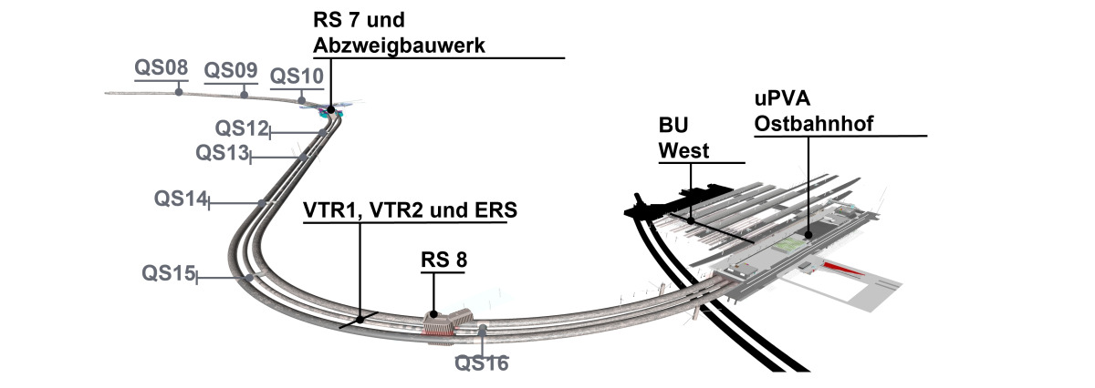 1 | Overview award unit VE 733
Credit/Quelle: DB Netz AG
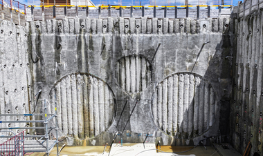
The two traffic tunnels as well as the exploration and rescue tunnel are mainly driven with tunnel boring machines with active face support and segmental lining. The eight cross-passages connecting the three tunnels are being built using the sprayed concrete construction protected by ground freezing measures. The deep-level East Station deep (with diaphragm wall construction) as well as the two rescue shafts RS7 (with diaphragm wall construction) and RS8 (with bored pile wall) are being constructed with the cut-and-cover method. The construction of the branch structure for the later connection of the south branch is carried out by dismantling and widening the TBM traffic tunnel sections in sprayed concrete construction starting from RS7. The new construction of the west platform subway from the new deep-level East Station to the existing station building is carried out with 13 auxiliary bridges supported on sheet pile walls.
1 TBM Excavation of Rail Tunnels and Exploratory and Rescue Tunnel
The nearly parallel tubes between Marienhof and deep-level East Station are being driven as circular rail tunnels with an excavation cross-section of approx. 9 m. The circular exploratory and rescue tunnel with an excavation cross-section of approx. 5 m is being driven using a shield TBM with active face support and a single-shell segment lining. The center distance of the traffic tunnels ranges between 18 m and 24 m.
The mechanized tunnelling starts in a temporary and pre-constructed launch shaft in the western part of the excavation pit of the deep-level East Station and heads in the direction of Marienhof. The TBMs are then pulled back to the starting shaft, where they are dismantled and extracted. The lengths of the drives are approx. 2850 m each.
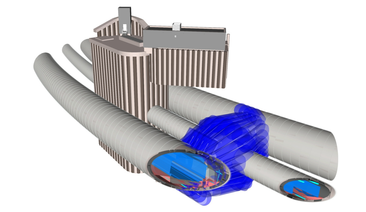
The exploratory and rescue tunnel, which is located in the middle between the rail tunnels, generally runs at the level of the planned escape route level of the rail tunnels and parallel to their tunnel axes. In the area of the RS7, the exploratory and rescue tunnel is raised above the line tunnel for geometric reasons, also in relation to the tunnel tubes of the south branch to be constructed later, and is routed north past the shaft structure of the RS7, with a separate access to the shaft (Fig. 2). For safety reasons, only vehicles with an electric drive are foreseen for the work in the tunnel areas.
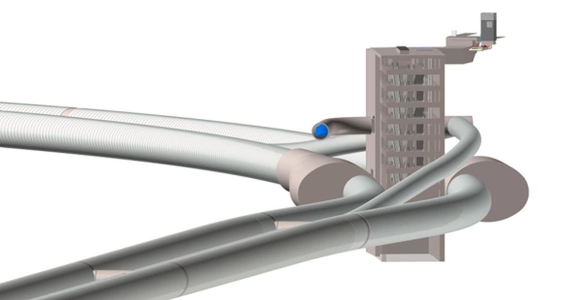 2 | 3D view of the alignment of the traffic tunnel and the exploratory and rescue tunnel in the area of rescue shaft 7
Credit/Quelle: DB Netz AG
2 Alignment and Structures From Deep-Level East Station to Marienhof
In the area connecting the tunnel tubes to the deep-level East Station structure, an approx. 11 m long „sealing block“ is being constructed using the jet-grouting method to improve the ground properties for the TBM exit from the excavation pit to the west of the diaphragm wall of the excavation pit enclosure. The supply and spoil disposal for the mechanized tunnel drives is carried out via the west starting shaft at the deep-level East Station. The central construction site facilities for the tunnel drives are also located there parallel to the railway in the Friedenstraße area.
Between the deep-level East Station and the RS8, all three tunnel tubes run under the operational DB track systems. The crown overburden (distance to ground level)
of the tunnels in this area ranges between approx. 9 and 13 m. Shortly after the start of driving from the west launch pit, the existing U5 subway line tubes are crossed at a close distance of approx. 2.1 to 2.7 m. The tunnel is then excavated at a depth of approx. 1 m.
Between RS8 and RS7, all three tunnels run under the Munich district of Haidhausen. The distance between the tunnel crown and the foundations of the structures here varies between approx. 20 and 28 m. Sensitive structures in this area include St. John‘s Church at Preysingplatz, built in 1912 and founded on piles, and the double-track rail tunnel of the 1st S-Bahn main line as well as historic beer cellar vaults.
The tunnel overburden is approx. 36 m in the area of the RS7 and decreases to approx. 14 m in the area of the Isar riverbed to then rise again to a maximum of 22 m towards the western bank of the Isar. Due to the elevation change, the exploratory and rescue tunnel passes underneath the Auer Mühlbach with an overburden of approx. 8.8 m. Additional emergency measures are planned here to prevent any accidents that may occur.
Immediately after the crossing under the Isar, the Prater weir will be passed under and the inner-city buildings will be traversed at a depth of approx. 30 to 40 m up to the Marienhof.
3 Cross-Passages
The transverse connections each consist of two short cross-passages (3.5 m high, 3.4 m wide) between the traffic tunnels and the exploratory and rescue tunnel. They will be double-shell constructions with a reinforced sprayed concrete outer shell and reinforced concrete inner shell made of in-situ concrete. All cross-passages will additionally be equipped with external sealing made of plastic sheet membranes (KDB), regardless of the water pressure level. The excavation and the support are carried out in sprayed concrete construction under the protection of a frost body. The opening of the cross-passages is foreseen with the use of steel segments.
The cross-passages 8 to 10 and 12 to 16 (Fig. 3) will be constructed according to the specifications of the fire protection and rescue concepts via the deep-level East Station or the RS7. Cross-passage 11 is located in the area of the RS7 and will be constructed conventionally under the protection of a groundwater relief system using compressed air tunnelling directly from the RS7.
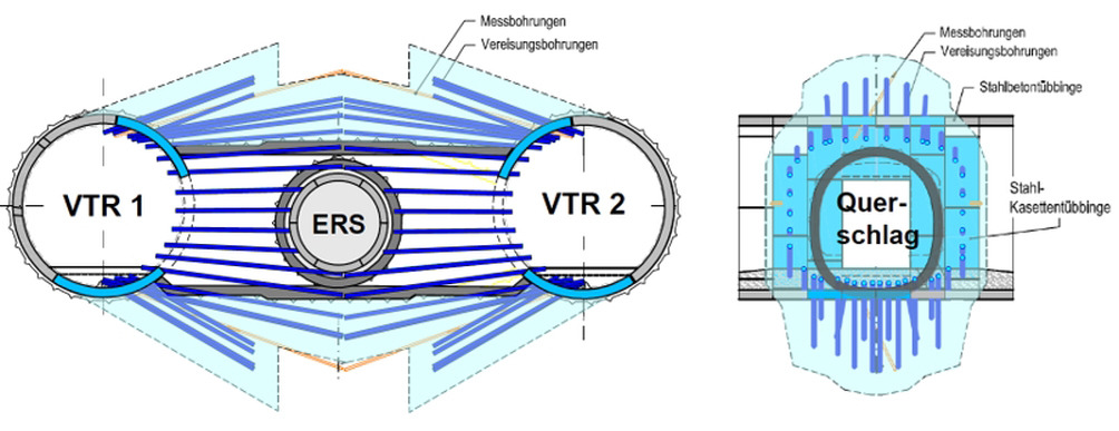 3 | Cross-sections of ground freezing in the area of the cross-passages
Credit/Quelle: DB Netz AG
4 RS7 Rescue Shaft and South Branch Structure
The rescue shaft 7, which is approx. 35 m long, 16 m wide and 39 m deep, will be constructed using the cut-and-cover method in an excavation pit enclosed by a diaphragm wall (55 m deep).
The traffic tunnel tubes and the exploration and rescue tunnel are connected to rescue shaft 7 via cross-passages that are constructed under compressed air. Vertical compressed air locks are provided in RS7 for this purpose.
The tunnel tubes (traffic tunnel and connection of the rescue tunnel) for the south branch structure will be constructed under compressed air using the sprayed concrete method. The tunnelling work will be carried out from the RS7 via the cross-passages there. They will be partially widened to form approach caverns during construction and then reversed accordingly in the final state (Fig. 4).
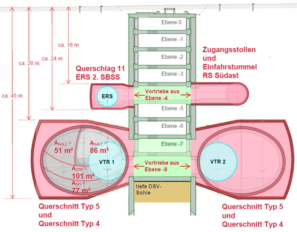 4 | Cross-section RS7 – looking in the direction of the deep level East Station
Credit/Quelle: DB Netz AG
At the eastern ends of the branch structure, „blind tunnels“ will be constructed for the subsequent connection of the south branch (Fig. 5),
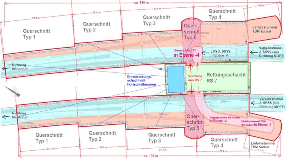 5 | Site plan RS7 and branch structure
Credit/Quelle: DB Netz AG
which will be backfilled with friction and insulated. The double-shell construction of the branch structures is made with a reinforced sprayed concrete outer shell and a reinforced concrete inner shell plus an external waterproofing system.
Dewatering in this construction area is ensured by vertical wells as well as by 80 m long horizontal wells for the construction of the branch structure from a drainage shaft integrated in the RS7.
5 RS8 Rescue Shaft
The rescue shaft 8, which is approx. 20 m long, 12 m wide and approx. 21 m high, is being constructed using the cut-and-cover construction method in an excavation pit enclosed by a bored pile wall. The structure is divided into five floors, with level E-4 as the escape route level (Fig. 6).
 6 | 3D view of RS8 and cross-passage 16
Credit/Quelle: DB Netz AG
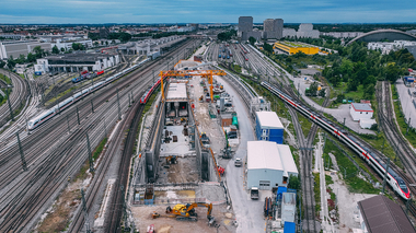
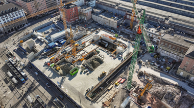
6 Deep-Level East Station
The new deep-level East Station will be used as an underground passenger transportation facility in parallel with the above-ground tracks of the existing East Station and the adjacent Friedenstraße. The new construction will have a rectangular ground plan, with a double-track station and a center platform.
The platform is located at a depth of about 16 m below the ground level. In addition to the entrance level (E0), the distribution level (E-1) and the platform level (E-2), the station consists of various intermediate floors for passenger circulation and technical areas. The construction area on the railroad site with a length of approx. 270 m and a width of approx. 33 m is located in the southern surroundings of Munich East Station and northwest of Friedenstraße.
The East Station is being built using the cut-and-cover method, with two shells, external diaphragm walls, primary supports and reinforced concrete inner shell. For structural reasons as well as for reasons of water impermeability, the diaphragm walls are 1.0 m thick and the inner walls 0.8 m thick. A 15 cm thick sprayed concrete layer is provided to compensate for construction tolerances. The roof deck will serve as a construction site set-up area and the western end will later serve temporarily as a starting shaft for the tunnel drives.
The installation of the primary supports, the bored pile foundations and the construction of the diaphragm walls will be carried out from the ground surface/pre-excavation level. The primary supports constructed in the course of this measure are for the most part final supports. They are designed to transfer very large building loads of a potential future superstructure.
The creation of the station construction pit is divided into two main sections: the west launch shaft (for the TBM) and the remainder of the station construction. At the western end of the station, the west launch shaft will be constructed first. A temporary diaphragm wall separates the west launch shaft from the construction area of the station. The construction of the launch shaft facilitates the advance of the TBM (in the direction of Marienhof) and, at the same time, the independent construction of the station carcass.
In the launch shaft, large access openings are provided for the TBM and other material transports, and three service openings are provided in the rest of the station structure for construction by the cut-and-cover method. The other service openings in the deck will have a consistent size of at least 10 x 5m.
The excavation pits are braced by the decks of different thicknesses and the roof deck as well as the 0.75 m thick intermediate ceilings (distribution floors). In addition, the construction pits (west launch shaft, remaining structure) must be back-anchored by a layer of double anchors at a spacing of approx. 1.8 m.
7 Dewatering
For the construction of the station, dewatering by means of internal and external wells is required. During construction, the diaphragm wall protects against groundwater inflow from the Quaternary and the Tertiary and connects to the damming clay layer below the Tertiary aquifer up to approx. 505 m NN. The uppermost Tertiary horizon as well as the Quaternary are enclosed by the diaphragm wall box. Both horizons are pumped during excavation with internal wells. Tensioned aquifers below the bottom edge of the diaphragm wall have to be depressurised during excavation by means of inner and outer wells. The dewatering by inner and outer wells must be carried out for as long as necessary to avoid hydraulic ground failure during the excavation process or until the superimposed loads from the weight of the concrete – with the concrete floor deck already constructed – are greater than the buoyancy.
8 Culverts
In the western area of the East Station with the tunnel system, the structures are located at right angles to the groundwater flow of the Quaternary groundwater. Groundwater transfers (culverts) are required to limit the resulting groundwater back-up caused by the parts of the structures located in the Quaternary. In addition, the groundwater must be temporarily diverted during the construction phase.
The first type of culvert is constructed from prefabricated shaft parts with a diameter of at least DN3000. The precast elements are sunk in advance at the shaft locations. The cutting shoe is located at the lowest shaft ring. Excavation is carried out on the inside by pressing down the shaft rings. At the same time, the structure is sealed against the Quaternary and Tertiary groundwater with underwater concrete at the bottom. This design is intended for culvert systems 1, 5 and 6, as these do not connect to a structure in open construction. The filter strings with total lengths between 15 and 35 m are driven from the shafts. They can be shut off with gates on the shaft wall.
The second type of culvert shaft has to be connected to the construction pit enclosure of the eastern railway station due to the existing railway tracks. The shafts are semi-circular and connect directly to the pit enclosure.
The shaft wall consists of a secant bored pile wall, which is connected to the excavation pit enclosure at each end via jet grout columns. The shaft radius is approx. 3.45 m. In the course of the excavation of the culvert shafts, slab plates with access ladders are constructed for bracing. For the construction of the culvert shafts 2 and 4, temporary dewatering by four external wells (one well per shaft) is required.
9 Outlook
Award unit VE 733 will be put out to tender in 2023 as an EU-wide negotiated procedure with a preceding call for tenders.
The section from the deep-level East Station in the direction of Leuchtenberg with award unit VE 734 will be published subsequently and includes approx. 500 m of compressed air excavation beneath the eastern track field as well as the rescue shaft 9 in diaphragm wall construction. Also assigned to this award unit is the Berg am Laim crossing, with complex traffic phases while maintaining public traffic (in particular the tram line), as well as the first construction section of the branching structure until the tunnel alignment resurfaces.
The award unit VE 833 with large railway operation components, such as numerous track switches and the new Leuchtenberg station, is published subsequently.