Planning and Building the Chancellor Line in Berlin/D
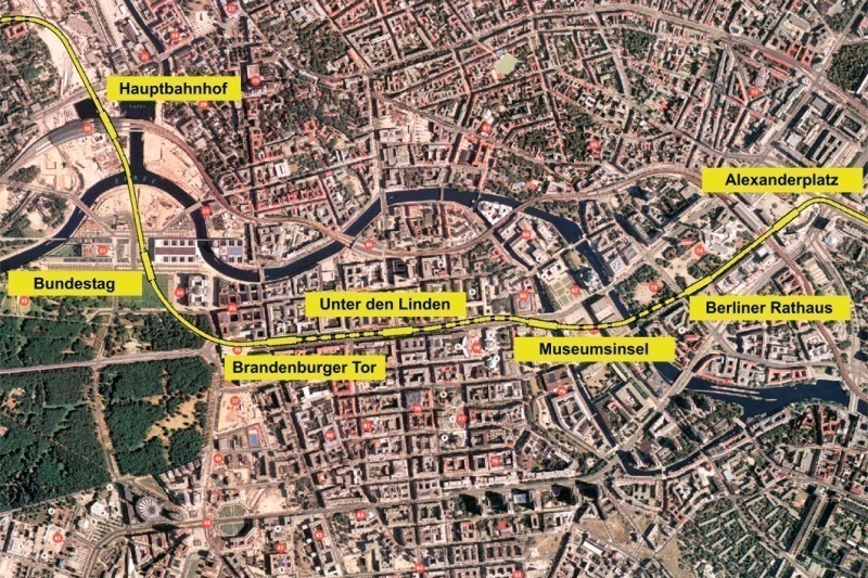
In August 2009 the new Metro section between the Central Station and the Pariser Platz, the first roughly 1.9 km long part-section of the so-called U5 Chancellor Line, was opened in the German capital Berlin. The Brandenburg Tor Station was the last structure to be constructed for the time being. This structure represents a part of the 2nd plan approval section running to the Berlin Rathaus, whose amendment plans are tabled for approval.
1 Introduction
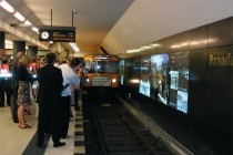
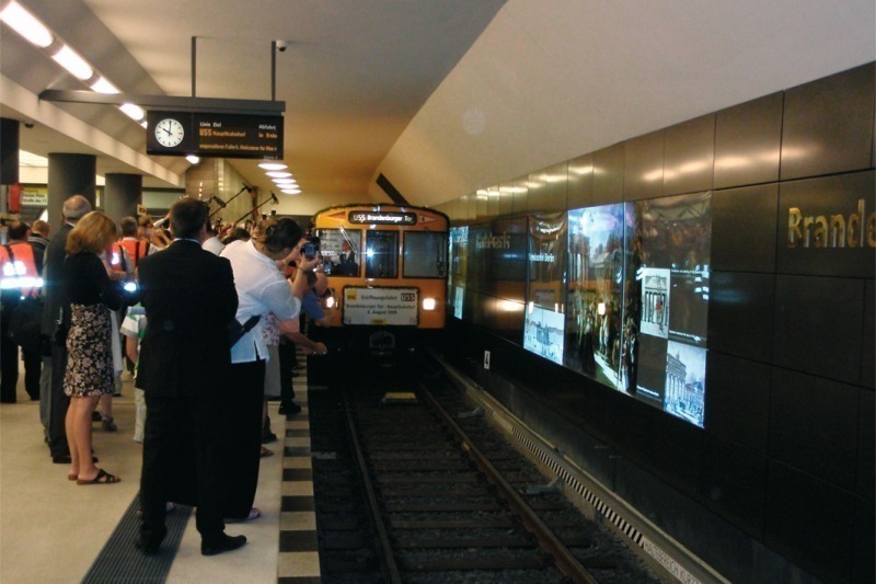
On August 8, 2009, the new Metro section between the Central Station and the Pariser Platz was opened by the Berliner Verkehrsbetriebe (Fig. 1). This means that the first part-section of the so-called Chancellor Line has been completed. The Brandenburg Tor Station was the last structure to be constructed for the time being. This structure represents a part of the 2nd plan approval section running to the Berlin Rathaus, whose amendment plans are tabled for approval (Fig. 2).
2 Brandenburg Gate Station
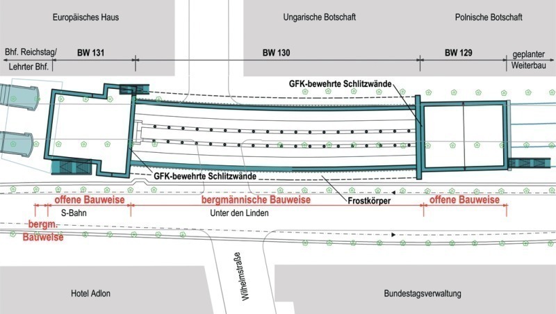
The construction areas for the station building are located in the immediate vicinity of the Pariser Platz with the Brandenburg Gate, the Hotel Adlon and further important and in some cases historic buildings along the street “Unter der Linden”.
To minimise nuisance to local residents in the new central area of Berlin, which also attracts large numbers of tourists, suitable trenchless construction methods had to be considered for the planning and execution phases. These were accordingly laid down within the scope of the 1999 plan approval proceedings. The parameters meant that the station consists of 4 structural parts:
■ The 2 entrance buildings at the east and west ends of the station (approx. 25 x 25 m), which were produced by cut-and-cover in partially covered and sealed diaphragm wall construction pits with excavation depths of 23 m,
■ The platform area, which was excavated from the construction pit for the eastern entrance building by trenchless means protected by subsoil freezing and
■ The roughly 6 m long, single-track connecting structures to the existing tunnel bores, which were produced by trenchless means protected by sealing zones of ice in a jet grouting zone.
Thanks to the fact that mainly trenchless means were applied, surface nuisance was kept to a minimum and important road connections especially the Unter den Linden and Wil-helmstraße intersection were maintained during the construction period.
The station building is altogether some 150 m long, with the platform area driven by mining means 92 m long. The vault cross-section possesses an area of some 180 m² and was designed as a 3-aisled cross-section with 2 rows of supports. The gradient in the station area rises only slightly from east to west at 1.5 ‰ so that the overburden amounts to roughly 9.5 m over the entire length given a practically horizontal surface.
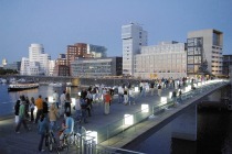
The new Metro station is located immediately alongside the north-south S-Bahn and provides transfer facilities from S-Bahn to Metro via the joint concourse (Fig. 3) on the west side.
3 Geology and Hydrogeology
The construction site is located in the Berlin glacial valley, one of the main courses taken by melting waters during the Weichsel glacial period. Typical of this area are Pleistocene deposits, some of which are more than 70 m thick consisting of sands and in part gravels with different grain fractions found beneath the existing buildings and fills. According to the extensive subsoil explorations undertaken in advance occasional coarse rubble (stones and blocks, layers of boulders) can be embedded there.
In some places cohesive boulder clay from the Weichsel and Saale glacial periods can be present in the sandy-gravelly layers, which are largely of a silty and clayey nature. In the Spree lowland area as well as the Spree Canal sapropel as well as organically permeated sands and silts (muds) can occur locally. Locally organic fills of sub-glacial troughs consisting of pronouncedly decomposed peats and peat muds as well as sapropel or lime muds containing lime are to be found.
The highest groundwater level expected was measured some 2 m and the lowest roughly 5.5 m below the ground surface. No significant groundwater current was identified in the entire construction area, which could have been of significance especially on account of the artificial ground freezing.
4 Dimensioning and Safety Concept for the Platform Structure
As trenchless construction protected by freezing was being employed for the first time
to this extent, the entire plan approval section up to Alexanderplatz was accorded a high safety level within the scope of the planning phase – back in 1998.
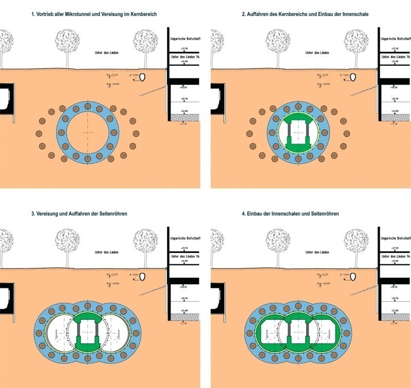
As a closed, watertight and temporary bearing structural element the creation of a frozen zone was planned to produce the Brandenburg Gate Station by trenchless means. The zone had to be capable of sustaining the full earth and water pressure for a defined period until the shotcrete shell hardened. After the shotcrete shell hardens it sustains the full earth and water pressure. Then the frozen zone only possesses a sealing function. The final structure is dimensioned against the full earth and water pressure as a watertight structure.
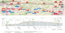
Based on this safety and dimensioning concept the construction sections for the trenchless excavation were to be planned in such a way that the above mentioned safety concept was applicable in every construction state. Fig. 4 presents the general construction sequence.
5 Construction Methods
The construction sequence according to Fig. 4 calls for the application of various special foundation engineering and tunnelling methods.
5.1 Microtunnelling
To establish the freezing zone lines have to be installed horizontally in the subsoil. Horizontal small drill holes were rejected as the required accuracy could not be assured given the existing column lengths of some 95 m. 30 microtunnels were used of about 1.5 m diameter with an overall driven length of some 2.7 km. The freezing pipes were then installed in these microtunnels.
The microtunnels were driven from the 2 construction pits by 2 tunnelling machines with fluid-supported face against the existing water pressure of up to 2 bar. The cutting wheel was equipped in such a way that obstacles like stones and blocks of up to 40 cm diameter could be penetrated. Recovery by manual means through the cutting wheel was foreseen for retrieving larger obstacles. However, this possibility was not resorted to for any of the 30 microtunnel drives.
A further major aspect concentrated on planning the microtunnel drives through the construction pit walls. Here it had to be taken into consideration that the microtunnels had to be driven upwards from below for safety reasons in order to assure access from the surface in the event of problems during excavation. Towards this end it was necessary to excavate the pits to their final depth and then carry out the drives.
5.2 Slotted Walls with FRP Reinforcement
As a result a main consideration in construction pit planning related to the starting-up procedures through the slotted walls. It has to be observed that the excavation states on account of the high groundwater, the effects of earth pressure on the preloaded soil and the need for construction with relatively low deformations led to high degrees of reinforcement of up to 160 cm²/m per side. When applying normal reinforced concrete reinforcement the microtunnelling machines, which are fitted for operating in soft ground, are not in the position to penetrate such quantities of reinforcement. As a result the reinforcement would have had to be removed manually prior to driving or the tunnel tracks kept free of reinforcement. This would only have been possible through applying complex additional measures.
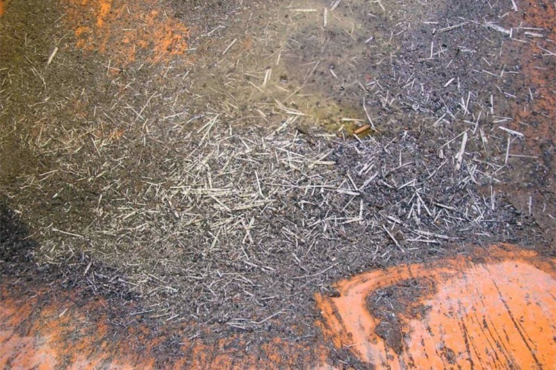
As a result glass fibre reinforced plastic (FRP) was foreseen to reinforce the start-up areas (Fig. 5). On account of the lack of a general permit from the construction authorities special approval (ZIE) was needed. No difficulties in penetrating the reinforcement cages occurred during the subsequent 30 microtunnel passages. The reinforcement shavings were recovered following separation (Fig. 6).
5.3 Subsoil Freezing and trenchless Excavation
The basic requirements on the dimensioning and planning of the freezing zone as a closed, watertight and temporary bearing structural element, the trenchless excavation with shotcrete supporting as well as a measurement programme accompanying construction to check the frozen zone’s quality have already been presented at length. Reference is made to the sources provided.
After excavating the 30 microtunnel drives and setting up the freezing plant the freezing pipes were installed along with the required measurement technology in the 30 microtunnels. The microtunnels were filled after the system was checked for pressure.
Subsoil freezing started with using the freezing pipes in the water-filled microtunnels in February 2007. Ring closure around the central tunnel was accomplished after roughly 8 weeks. This was indicated by the activation of the pressure sensors and the water level lines. Approx. 3 months after activating the freezing zone its statically required thickness was attained so that driving operations for the central tunnel could be started. Controlling the freezing process and in turn the frozen zone was switched from start-up mode to intermittent retention mode from this point in time.
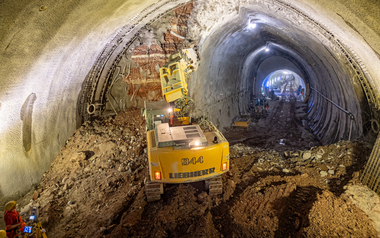
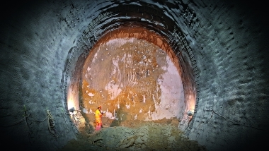
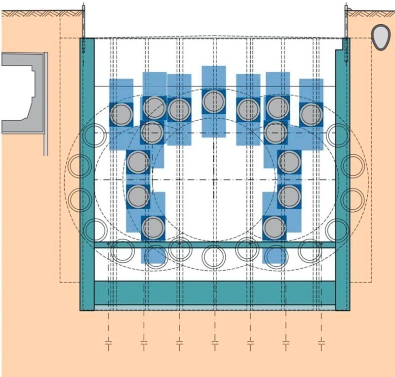
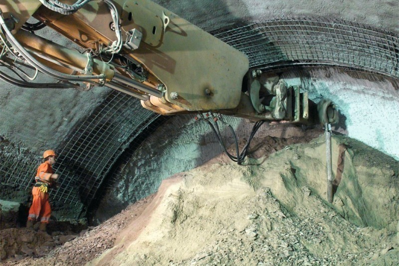
After establishing the frozen zone the station cross-section was driven in part-sections from the eastern construction pit. As foreseen at the planning stage the frozen zone had become incorporated in the excavated cross-section (Fig. 7).
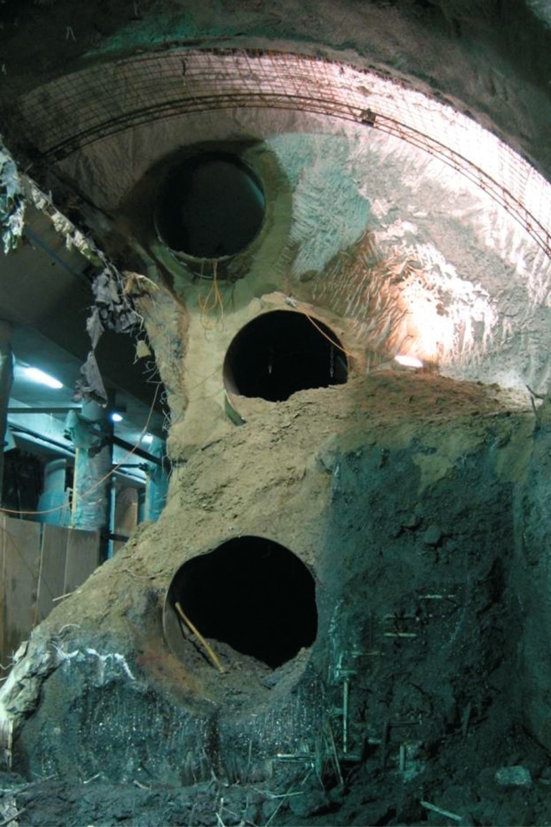
Temperature measurements in the excavated cross-section revealed temperatures considerably below the frost limit at places. However directly at the surface on account of the surrounding temperatures of roughly 20 to 25 °C the sand quickly thawed. Berlin Sand proved to be stable during the trenchless excavation after continuous drainage. Towards this end the microtunnels had to be removed in the core area. In order to simply the process the microtunnels were filled with water – in accordance with a special proposal by the JV U55 – and frozen. In this way during the removal phase the water content was actively thawed and the pipes cut from the inside and retrieved segment by segment (Fig. 8).
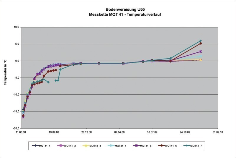
In summer 2008 the entire trenchless excavation including the installation of the tunnel structure was completed and the frozen zone’s retention mode was ceased. The temperature measurement programme and the accompanying surface measurements were nonetheless continued until the frozen zone had thawed completely. The time point of thawing was defined as when the frost limit at all measurement points had been exceeded.
As can be discerned from the temperature curves (Fig. 9) this thawing process was first completed at the end of 2009. The lengthy thawing phase is attributable to the ground-water’s low flow speed. The resultant special surrounding temperatures had to be taken into consideration when building the underground station structure. On account of the high temperature gradient, condensation formed in the platform area, which was countered by permanent mechanical ventilation during the support operations.
6 Outlook
After commissioning the first sections planning is now forging ahead for continuing construction so that roughwork operations will be able to start in 2010. Preparatory work in the archaeological field as well as relocating lines is already in progress. Towards this end extensive special foundation engineering and tunnelling methods will be applied. The findings gained during the building of the Brandenburg Gate Station will represent a useful basis for this purpose.