Project P-Option in Stuttgart – Section BA I: Construction Works Completed Ahead of Schedule
As part of the Stuttgart–Ulm railway project, the entire Stuttgart rail hub is being reorganised. With the start of operation of the project, the long-distance railway tube of the Prague Tunnel, which is over 100 years old, will become dispensable. The P-Option (Prag-Option) project will also use this tunnel to create a new double-track connection between Stuttgart Central Station and the 4800 line in Feuerbach.
 Project P-Option, construction phase I: Tunnelling work in one of the two branching structures of the Cannstatt Tunnel for the underground connection to the planned new Wartberg Tunnel
Credit/Quelle: Jannik Walter/DB PSU
1 Project
As part of the Stuttgart–Ulm rail project, the entire Stuttgart rail hub is being reorganized. The future Stuttgart main station will be rotated by 90° compared to its current location and converted into a through station. Long-distance and regional traffic from Munich will reach the new main station via the Filder Tunnel (route 4813). In the direction to Mannheim, the main station will be connected to route 4800 via the Feuerbach Tunnel. Furthermore, tunnels to Bad Cannstatt and Ober-/Untertürkheim have been constructed within the city of Stuttgart.
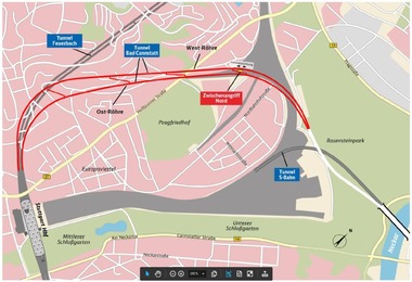
 1 | Overview map
Credit/Quelle: WBI GmbH, Hintergrundkarte: basemap.de / BKG 08.2022
 2 | Wartberg Tunnel, plan view
Credit/Quelle: WBI GmbH
As a consequence of start of operation of the new railway project Stuttgart–Ulm parts of the existing infrastructure will be dispensable. The more than 100 years old Prag Tunnel is one of these structures. By means of the project P-Option (Prag-Option) a new double-track connection between the new central station and the route 4800 in Feuerbach will be created using this old tunnel. The tracks of the P-Option branch off from route 4715 in the existing Cannstatt Tunnel. The tracks of the new line 4806 run from here in the new Wartberg Tunnel to the northwest. The portal of the tunnel is located west of the Löwentor Bridge on Heilbronner Street (Fig. 1).
A trough structure adjoins the tunnel to the west. The tracks reach the current ground surface immediately to the east of the existing Prag Tunnel. However, the P-Option also includes measures in the existing Prag Tunnel of route 4800 to the west, which was built at the beginning of the last century, and the subsequent section to Feuerbach, where the line will connect to the future route 4813 in the direction of Mannheim.
The P-Option will be realized in three construction phases (Fig. 2). Construction phase BA I comprises the direct underground connection area to the Cannstatt Tunnel. Construction phase BA II includes the single-track Wartberg Tunnel tubes to be excavated by the mining method, a connecting structure, fan structures and the associated technical shaft as well as a technical building. Construction phase BA II ends in the north and northwest in the area between the Brünner Steg and the Löwentor Bridge. Construction phase III comprises the adjoining sections of the Wartberg Tunnel to be constructed by the cut-and-cover method, the trough structure and measures in the Prag Tunnel.
2 Ground and Groundwater Conditions
 3 | Leached gypsum keuper at the tunnel face in branching structure 4806-2
Credit/Quelle: WBI GmbH
 4 | Leached gypsum keuper, soil and rock mechanical model
Credit/Quelle: WBI GmbH
In the project area, the layers of gypsum keuper lie beneath the cover layers of quaternary deposits and artificial fills, which can be several meters thick. The gypsum keuper layers in the planning area of the Wartberg Tunnel are continuously present in leached form up to the transition to the underlying Lettenkeuper (Fig. 3). The leached gypsum keuper (AGK) was formed when the sulphate components of the rock were dissolved in water and transported away with the groundwater flow. The rock can be divided into four classes according to its degree of leaching and strength (Fig. 4). Classification is possible on the basis of the natural water content [1]. On this basis, the AGK in the area of the underground branching structures (construction section BA I) can predominantly be assigned to classes II to III [2]. The relevant characteristic values for these classes are summarized in Fig. 4.
The groundwater conditions in the area of the Wartberg Tunnel are characterized by the alternating sequence of layers that have different permeabilities. This results in multi-layered groundwater systems with different interactions between the individual levels. The vertical water permeabilities are relatively low in the leached gypsum keuper. Horizontally, the vertical fracturing of the friable siltstone layers usually results in somewhat higher permeabilities.
The construction project is located in the inflow area of the mineral springs of Stuttgart-Bad Cannstatt and Stuttgart-Berg. They are located in the outer zone of the designated spring protection area [3].
3 Planning of Construction Section BA I
 5 | Bad Cannstatt Tunnel, special profile SQP in the area of the planned branching structure for the P-Option
Credit/Quelle: Jannik Walter/DB PSU
 6 | Wartberg Tunnel, 3D view
Credit/Quelle: WBI GmbH
 7 | Branching structures, cross section in the area of maximum width
Credit/Quelle: WBI GmbH
 8 | Branching structure Presselstraße, lower tube
Credit/Quelle: WBI GmbH
 9 | Excavation and support for the construction of the branching structures
Credit/Quelle: WBI GmbH
Construction section BA I comprises the immediate connection areas of the P-Option to the existing Cannstatt Tunnel and the adjoining approx. 20 m long sections of the single-track Wartberg Tunnel tubes (Fig. 2). The planning was carried out using the BIM method. The basic evaluation for the project began in the year of 2021.
The location of the connection area for the P-Option was already defined in principle during the planning of the Cannstatt Tunnel. Here, the Cannstatt Tunnel was designed as a preparatory measure in a special profile ([2], Fig. 5 and Fig. 3, right). The tubes of the Cannstatt Tunnel were planned at different depths so that the outbound tube of the Wartberg Tunnel can cross over the inbound tube of the Cannstatt Tunnel (Fig. 6).
The upper tube of the Wartberg Tunnel with the Feuerbach directional track (axis 4806-1) runs from the connection area to the north and northwest. In the intersection area with the inbound directional track of the Cannstatt Tunnel, the distance between the floor of the Wartberg Tunnel and the roof of the Cannstatt Tunnel is only a few meters. The overburden to the ground surface, the track systems and buildings located here also measures only a few metres (Fig. 7).
The gradient for track 4806-2 initially runs from the junction structure with a 40 ‰ uphill gradient in the direction of the Prag Tunnel. The steep gradient is necessary for the track to reachethe ground surface east of the Prag Tunnel. Due to the large gradient, the tracks already have a height difference of approx. 1 m at the end of the approx. 100 m long branching structure (Fig. 8). The tunnel cross-section here has a width of 20.6 m and a height of 14.2 m in relation to the outer edge of the inner lining.
To widen the tunnel in the area of the branching structures, the inner lining of the Cannstatt Tunnel had to be dismantled in the affected area. For this purpose, the groundwater level was first lowered by drilling. The excavation and widening were carried out using the sprayed concrete method under the protection of a pre-support with pipe umbrellas (Fig. 9). In order not to additionally increase the cross-section height, the pipe umbrellas were drilled on the fly from the face. The pipes located inside the excavation contour were cut off in the course of heading.
 10 | Excavation and support works in a branching structure
Credit/Quelle: Jannik Walter/DB PSU
Heading was planned as a full excavation with a stepped face (Fig. 10). The pull-out lengths were planned with a maximum of 1 m. To limit the subsidence caused by the excavation, a heavy face support and a ring closure after 5 m at the latest were planned (Fig. 9). Both the design of the support and the prediction of subsidence were carried out with the aid of 3D FE analyses. Corresponding analyses were carried out both in the preliminary design phase and in the design for execution phase. In the course of the construction work, the predictions were continuously compared to the measurement results. On this basis, it was possible to confirm that the characteristic values are decisive and that it is possible to eliminate the consideration of lower boundary values. This made it possible to avoid execution of compensation grouting measures originally planned in the area of the buildings at Heilbronner Str. 150 and Presselstr. 10 and 12.
4 Construction
 11 | Heading diagram
Credit/Quelle: WBI GmbH
 12 | Subsidence of the buildings due to excavation for the lower branching structure 4806-2
Credit/Quelle: WBI GmbH
 13 | Subsidence of the buildings due to excavation for the branching structures 4806-2 and 4806-1
Credit/Quelle: WBI GmbH
The widening for the branching structures was carried out via the intermediate access (ZA) North, built for the construction of the Cannstatt Tunnel – first for the lower structure (main station directional track) and then for the higher structure (Feuerbach directional track). In order to enable the construction measures, the already completed cross passage 1.5.2.3 was opened. In the construction area of the Cannstatt Tunnel, the already installed equipment components as well as the slab track were dismantled or protected against damage. The inner lining was then dismantled.
The tunnelling work in the lower branching structure began in November 2023 and was completed in April 2024. Driving in the upper branching structure took place in the period from September 2024 to January 2025. Average advance rates of 0.8 to 1.0 m/d were achieved for the widening (Fig. 11).
The subsidence measured at the buildings as a result of the construction of the lower branching structure is shown in Figure 12. The results correspond to the predictions as it was observed for the subsequent construction of the upper branching structure (Fig. 13).
Thanks to the excellent cooperation between all involved parties, construction works were completed ahead of schedule.
5 Outlook
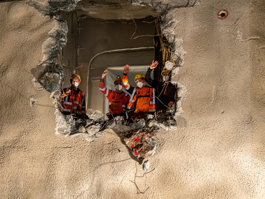
Construction of section BA I of the P-Option was completed less than five years after the start of preliminary planning (Fig. 14). This was possible thanks to the excellent cooperation between all parties involved. The plans for construction sections BA II and BA III are also on schedule. The plans for section BA II are currently in the approval process at the Federal Railway Authority. The preliminary planning for construction section BA III, which began at the start of 2025, is planned to be completed in 2026.
 14 | Branching structure for the lower tube after completion
Credit/Quelle: Jannik Walter/DB PSU