Access Adit I for Kraftwerke Linth-Limmern
The Linthal 2015 project for Kraftwerke Linth Limmern AG (KLL), Switzerland, covers the comprehensive expansion of KLL‘s facilities including, inter alia, headrace tunnels, machinery and transformer caverns. The work on Access Adit I to provide access to the machine chamber during the equipping and operational phases is the focus of the following article.
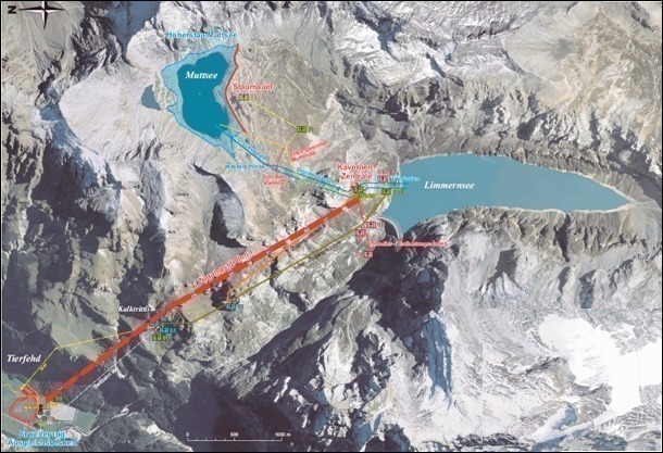
Lot A1 is a component of the Linthal 2015 project for Kraftwerke Linth-Limmern AG (KLL), which will include comprehensive expansion of KLL‘s facilities. An additional balancing reservoir is to be created in the vicinity of Tierfehd, and the new Limmern pumped-storage plant installed between the high-altitude water reservoirs of the Muttsee and Limmernsee lakes. These two lakes are to be linked by means of two additional headrace tunnels, which will open at the Limmernsee end into a machine chamber housing four single-stage pump-turbines, each of 250 MW, to convert the water‘s kinetic energy to electricity.
In addition to the construction of the headrace tunnels and the machine chamber and transformer cavern, a new dam is to be built on the Muttsee, in order to increase this lake‘s storage capacity. This work is part of Lot A2. Other works necessary for implementation of the Linthal 2015 Limmern pumped-storage hydroelectric power plant are to be implemented in further contract lots. Access Adit I for access to the machine chamber during the equipping and operational phases is one of these lots (Fig. 1).
1 Access Adit I in Lot A1
Access Adit I is to be constructed, starting from Tierfehd, in order to provide all-weather access to the machine chamber and transformer cavern during the subsequent utilisation phase. In its ultimate expansion stage, this access adit will be equipped for conveyance of persons and of heavy machine components by means of a funicular. The outgoing energy supply cables will also subsequently be accom-modated in the side berms of the access adit.
The access adit consists of a number of components:
■ the cut-and-cover tunnel, complete with portal structure
■ the access passage to the lower terminus
■ the lower terminus cavern
■ the inclined adit with the passing station at the half-way point
■ socket recesses at regular intervals along the inclined adit
The 18 m long tunnel and portal will be constructed using the cut-and-cover method from the pilot cut. This will be followed by underground tunnelling of the access way to the lower terminus, which will have a length of around 219 m and, on the basis of the project draft, an excavated cross-section of some 50 m2. Tunnelling is to be accomplished by means of drilling-and-blasting (D&B) methods. The lower terminus cavern, with a length of 35 m, will follow. The excavated cross-sections will be around 260 m2 (standard section), and 360 m2 in the widened zone.
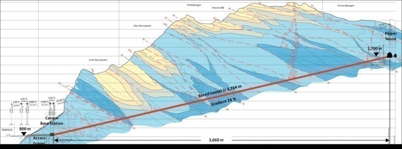
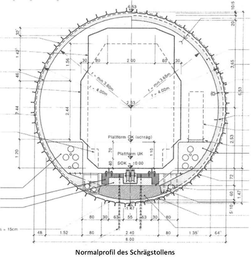
The 3764 m long inclined adit is to be tunnelled using a TBM, starting from the cavern and terminating in the machine chamber. The adit will run at a gradient of 24 %, in order to overcome the height difference of around 900 m between the lower terminus and the machinery house. As far as the project planners are aware, this will be the first time anywhere in the world that an underground incline of this length with a gradient of 24 % and an excavated diameter of 8.03 m has been created. These conditions and dimensions will impose extraordinary demands on the tunnelling crews and their equipment.
The seventeen socket recesses located at intervals of 550 m along both sides of the inclined adit are to be created in parallel to TBM tunnelling. Construction of the passing-point at the mid-way mark in the adit is planned for the period after completion of the tunnelling operations.
2 Geology
Access Adit I is located entirely in the Quintner limestone formation, which can, in general, be regarded as offering favourable conditions for tunnelling. There are, however, sections featuring unfavourable intersections of cleavage planes (multiple cleavage planes and only short intervals between them), which result in unstable elements on the periphery detaching from the formation and falling into the tunnel cross-section.
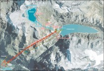
Karst phenomena are possible in the Quintner limestone; thanks to the low underground water table, it is assumed that no influxes of water capable of significantly obstructing tunnelling will occur, however. Such Karst inclusions are in many cases filled with sediments. Extensive forward exploratory work is planned, in order to permit detection at the earliest possible stage of any such special features. Seismic methods, combined with forward drilling from the cutter head, will be used (Fig. 2).
3 Drilling-and-blasting tunnelling for the access adit and cavern
The access adit was struck in January of 2010, following the creation of the pilot cut by means of drilling and blasting, and its securement by means of rock nails, reinforcement mesh and shotcrete. The first blasting operation took place on January 19, 2010.
Tunnelling for the first few meters of the adit was accomplished by means of partial-face tunnelling, due to the low overburden cover under the sloping surface. It was then possible to blast the full cross-section. Support of the cross-section in the adit consists of shotcrete, reinforcement mesh and grouted rock bolts of 3 to 4 m in length.
It should also be noted that the 50 m2 cross-section originally planned for the adit has been enlarged for operational reasons to around 70 m2; the background to this change can be found in the company‘s decision to assemble the TBM in front of the tunnel portal and draw it into the starting bore complete with the back-up system.
Excavation of the lower terminus cavern was started after completion of the tunnelling work for the adit. The partial-face method was also used here for tunnelling. The lining, consisting of shotcrete and reinforcement mesh, was also installed in a follow-up working operation during the support work for the crown and bench.
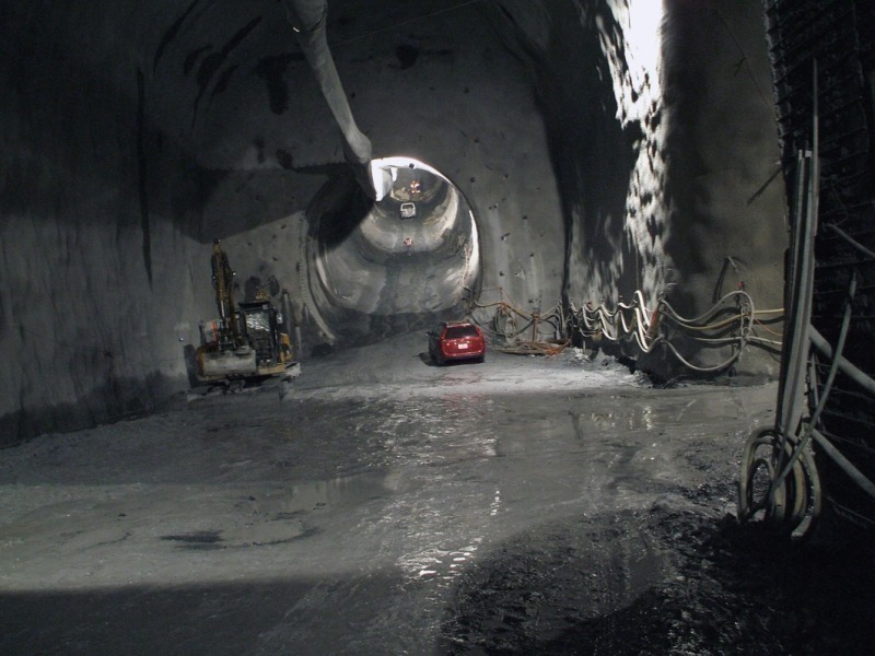
The starting adit for the TBM was then drilled and blasted from the cavern, and support then installed. The inclined length of the adit is around 100 m (see Fig. 3).
4 TBM tunnelling for inclined adits
4.1 TBM and back-up system
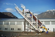
A TBM with an appropriate back-up system will be used for heading of the inclined adit (Fig. 4). Special requirements for this installation result from the gradient and the residual risks presented by the Karst. It must be possible to overcome cavities, and to master boring through concealed Karst inclusions while, at the same time, the crew‘s workplaces are required to satisfy extremely high safety standards. These demands can best be fulfilled by means of a high level of workplace mechanisation.Unlike the situation in conventional tunnelling operations, it is not the actual rate of TBM advance which is definitive here for tunnelling progress, but instead performance in forward exploration, rock reinforcement, shotcrete lining – which is to be installed from the back-up system during active tunnelling –and supply logistics. The invitation to tender required a TBM with double bracing. The contractor‘s bid met this requirement with a single-gripper machine, which also featured a forward bracing facility. A double-gripper machine was also offered as an option, which the client, however, declined. The contractor, tak-ing account of all the technical and economic requirements, decided during the evaluation phase in favour of a TBM in the form of an open hard-rock machine with a double gripper. This machine has a tunnelling diameter of 8.03 m, and a total installed power of around 3500 kW.
The cutter head carries sixty-two roller cutters of 17“ diameter, of which two take the form of bore disk cutters. The tunnelling muck is conveyed by the back-rakers via the drilling booms to the muck hopper, which transfers it to the machine conveyor, which then feeds it on to the belt in the back-up train.
Support work, such as the installation of shotcrete, segmental arches and drilling of rock bolts, can be performed in Zone L1 if necessary, i.e., only shortly behind the cutter head. The TBM is also equipped with forward exploration facilities which permit drilling of exploratory bore holes of up to 100 m in length and 100 mm in diameter.
The back-up system consists of eight back-up cars, which are coupled to the TBM by means of tow-bar couplings. A hold-back, which is intended to prevent the tunnelling train (the TBM and its back-up system) sliding down the inclined adit in case of failure of the support system and during repositioning of the TBM, is installed between the back-up system and the actual TBM. This system mechanically braces with a lever action against the periphery of the excavated section as soon as compressive forces from the TBM or tensile forces from the back-up system act upon it (Fig. 5).
The front back-up units carry equipment for supply of the TBM, and also the control pulpit. The equipment for installation of the inner lining is located on Back-up Car 3. Other equipment, such as safety containers, a workshop, transformers, ventilation systems, shotcreting pumps and the TBM cooling system, is located on the following back-up cars. The complete tunnelling train – from the front face of the TBM to the tail of the back-up system – has a total length of some 165 m.
Particular attention was devoted during the conception phase for the back-up train to ensuring that conveyance of building materials from unloading from the supply train up to the point of installation can be accomplished with the greatest possible level of mechanisation. A further important aspect, due to the special boundary conditions for operation of the conveying equipment, was that of assuring sufficient storage space for building materials, in order to buffer any delays in supply.
4.2 Logistics of tunnelling operations
Since supply of the tunnelling operation by means of tyred vehicles had been excluded by the client for safety reasons, the contractor decided in favour of the use of a cable-hauled rail system. The capacity profile for this system derives from the quantities of material necessary for tunnelling, the shotcrete requirements for lining installation and the planned rates of tunnelling advance. The cycle-time for a train set depends on the distance to be travelled, travel speed, and the loading and unloading of the train. These parameters indicated the necessity for a payload of around 50 t.
The winch installed on the back-up train for haulage, due to its dimensions – 2000 kW drive rating and a total weight of 110 t (including 3900 m of cable, of 43 mm diameter) – made special additional demands on the back-up train, its clearance profiles and on the catwalks, walkways and escape routes.
The cable-hauled rail system comprises a train unit consisting of several wagons, these wagons being designed as multipurpose modules, i.e., various accessories can be mounted on them. One train unit consists of three modules, each around 10 m in length. The first module carries the control pulpit and various items of equipment required for loading and unloading of Modules 2 and 3. These modules can be flexibly equipped, depending on what is to be transported and what work is to be performed.
These units are hauled by the cable-winch mentioned above. The wagons in the train unit are rail-guided and run during tunnelling operations on the floor segments installed underneath the back-up train.
The cable-hauled rail system is one of the central elements of the tunnelling equipment, and a key system. It is also to be used for recovery of the back-up train elements after the completion of tunnelling.
Outward conveyance of the excavated material from the end of the back-up train belt is by means of conveyor-belt cascades. These consist of individual conveyor-belts, of a length of 275 m each, which are successively installed in the inclined adit as tunnelling progresses. A trailing conveyor of appropriate length is provided in the back-up train in order to ensure that the gap generated during tunnelling between the trailing end of the back-up train and the end of the most recently installed conveyor-belt can be bridged. This discharges the material fed on to it by the back-up train belt on to the nearest cascade belt. This solution, in the contractor‘s opinion, provides greater reliability and safety in case of a belt breakage than the variant utilising a continuous belt. It also offers the advantage that standard, conventional belt types can be used.
5 Work status and envisaged completion date
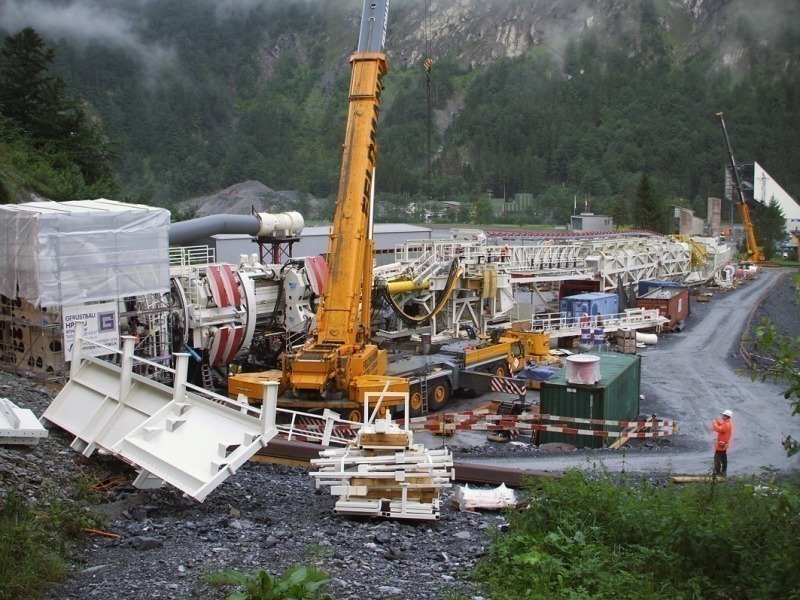
As at mid-October, the starting adit and the cavern had been prepared for insertion of the TBM and back-up train into the starting bore. The TBM and back-up train had been completely assembled and had already been run into the starting adit from the portal.
Tunnelling started in the 42nd week of 2010, initially using a temporary supply system. Tunnelling of the inclined adit and dismantling of the tunnel-boring equipment is scheduled for completion by the end of 2011.