Minimising Risks through complex Groundwater Management for the Amsterdam North/South Line
Amsterdam’s historic centre is to be linked to the northern and southern suburbs by means of the new 9.7 km long North/South Metro line. The following report examines the project’s complex groundwater management.
North/South Line Project
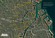
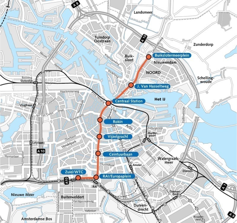
Amsterdam is engaged in building a new Metro line, the North/South Line (Noord/Zuidlijn). The core of Amsterdam, the historic downtown area, is to be linked directly with the northern and southern suburbs by means of this connection. With an overall length of 9.7 km the Metro will run from the north via the stops Buikslotermeerplein, Johan van Hasseltweg, Centraal Station, Rokin, Vijzelgracht, Ceintuurbaan and Europaplein to the Zuid/WTC Station. Fig. 1 shows the route alignment.
The 2 northern stations are to be constructed above ground. Then the line will run for a distance of 7.5 km underground, with 3.8 km driven by mining means, below the IJ, the Centraal Station as well as the city centre until the Europaplein. The terminal Zuid/WTC Station already exists and like the Centraal Station affords opportunities to transfer to the existing Amsterdam Metro routes as well as regional and mainline trains. Work commenced in April 2003. The first trains are scheduled to run over the new route in 2017.
Station Vijzelgracht
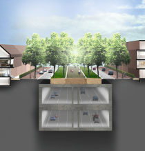
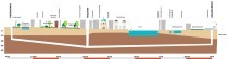
Hölscher Wasserbau GmbH has been commissioned to undertake the groundwater management at Station Vijzelgracht. Along with Rokin and Ceintuurbaan, Vijzelgracht is numbered among the deepest stations (roughly 30 m excavation depth) along the route. The approx. 18 m wide Metro station is some 270 m in length. Fig. 2 displays a longitudinal section of the planned Metro station.
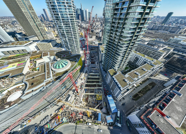
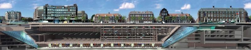
A diaphragm wall box has been created down to a depth of about 45 m. The diaphragm walls are set up in such a way as to cope with the changing flow of traffic. The cut and cover method was selected to ensure that road traffic could be kept running during the period of construction and avoid influencing the surroundings to an excessive degree. Reinforcing beams as well as the scheduled intermediate ceiling were installed as the pit was being excavated. Once the final depth is reached the tunnel boring machines will pass through the Vijzelgracht. In its final state the Metro trains will run at the lowest level of the station. The space above the actual Metro station will probably partially be used as an automated parking facility.
Geology
Maritime sedimented soft ground in the following sequence is located at the station/excavation pit Vijzelgracht in the centre of Amsterdam:
• Surface level approx. 1.0 m NAP(“Amsterdam Ordnance Datum” – corresponding to m ASL)
• Fill down to a depth of - 2.0 m NAP
• to - 4.5 m NAP Hollandveen
• to - 7.0 m NAP old marine clay
• alternating marine sediments till - 12.5 m NAP
• to - 14.0 m NAP 1st sand layer
• to - 17.5 m NAP Alleröd sediments
• to - 26.0 m NAP the 2nd sand layer
• to - 28.5 m NAP transition layer
• then the decisive marine deposit as a practically impermeable layer of so-called Eem clay down to the base of - 40.0 m NAP in the north and
• - 41.0 m in the south of the excavation.
The underlying intermediate layer of sand, which is only 0.5 to 1.5 m thick, represents a serious potential danger for a hydraulic shear failure as a confined aquifer carrying only little water. The permeability coefficient kf averages out at 10-5 or between 2 x ·10-6 to 2 x ·10-5 in the border areas. In geotechnical terms the intermediate sand layer is an ultra fine sand with a 15 to 20 % of silt.
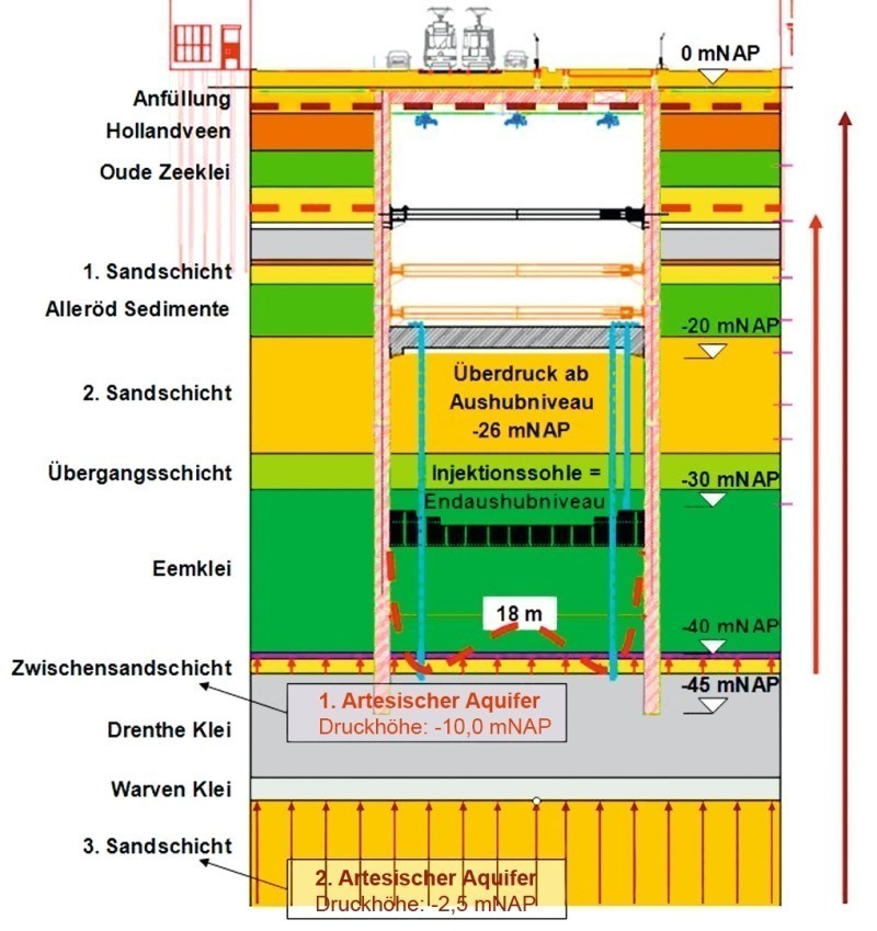
Glacial Drenthe clays and Warven clays are to be found underneath with a total thickness of 9.0 m before the confined, water-bearing third sand layer begins. Fig. 3 presents the soil strata together with the structural cross-section.
Task
The respective water levels of the intermediate sand layer amount to - 10.0 m NAP in the north and - 17.0 m NAP in the south as established by the existing system of measuring points. In the 2nd artesian aquifer of the 3rd sand layer pressure levels of - 2.5 m NAP have been established. Fig. 3 displays the hydrogeological situation.
These water levels lead to the danger of a hydraulic shear failure given the required maximum excavation down to - 32 m NAP. Hölscher Wasserbau GmbH’s groundwater management embraces the pressure relief for the intermediate sand layer as foreseen in the construction process, which is necessary in addition to the main dewatering system (draining the excavated sand layers). The 3rd sand layer remains unaffected. There are 2 decisive failure possibilities, first of all the breaking up of the soil of the intermediate sand layer and secondly from the 3rd sand layer.The number of necessary drawdown wells for the intermediate sand layer resulting from the large excavation pit dimensions is intended to reduce the danger of related shear failure. The prevailing ultra fine sand with the low permeability coefficient led to the technical proposal to install the drawdown wells in the form of vacuum deep wells. In this way safety could be arrived at through improved drainage and an enhanced soil-stabilising influence thanks to the vacuum effect. Furthermore an overpressure system secures the subsoil against loosening caused by the 3rd sand layer from an excavation depth of - 26.0 m NAP as a further safety precaution.
A further requirement was the application of the largest possible gaps between the wells as well as having to avoid placing them through the centre of the excavation pit. In this way a more rapid and economic excavation was to be assured.
In addition there was the challenge of assuring that the deadlines for executing the installation of the wells were adhered to in order to ensure that the excavation and concreting operations were not hampered. This was achieved by a logistically sophisticated division of labour involving a number of drilling crews.
Furthermore the confined water conditions prevailing in the intermediate sand layer had also to be mastered in drill technical terms quite apart from the previously mentioned ones. Towards this end the series of filter routes in the aquifer were used in order to undertake pumping operations intended to relieve pressure. As a result the drilling operations were tackled safely and accomplished using material for supporting the wells as well as clay and sealing materials.
The System
The previously mentioned requirements were fulfilled using a system comprising vacuum deep wells and complex control technology.
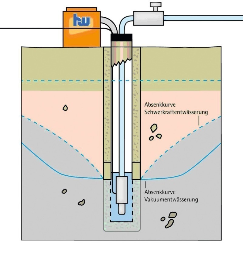
Vacuum deep wells are deep wells with the additional use of vacuum inside the well. In this way the characteristics of the lowering effect are also changed for the aquifer that has to be relieved. The draw down curve is increased in the applied system through the creation of vacuum. The effective well zone and the drainage curves alter in a practical fashion. This caters for a greater amount of ingressing water as well as a larger relief effect. This leads to an extended, constant inflow area at the point of withdrawal in contrast to the gravitational flow (Fig. 4).
Through the greater amount of water to be pumped away, which increases in proportion to the relief gradient, a lower maximum value for the pressure head in the excavation pit is attained as well as the same drainage level given a greater gap between wells. Greater gaps between wells ensure that the space within the pit is essentially kept free.
During the 1st operating phase the vacuum drainage alone enables the excavation of – 22.5 to – 26.0 m NAP. During the subsequent excavation phase down to the final depth of – 32.0 m NAP compressed air is additionally introduced into the pit in order to prevent the soil loosening. The magnitude of the overpressure introduced into the excavation pit depends on the pressure head in the intermediate sand layer and the pressure head of the 3rd sand layer attained by the groundwater management. As both systems can be harmonised with one another, they afford the greatest possible safety. It should be mentioned though that the compressed air system would not be desirable on its own and that relief on its own could not assure complete safety. Given relief on its own, the pressure of the underlying, non-relieved 3rd sand layer would become a problem. Securing the subsoil solely with the overpressure system would lead to higher overpressures and reduce the working times in the overpressure area greatly for reasons of occupational safety thus thwarting an economic construction process.
Set-Up of the Groundwater Management Well System
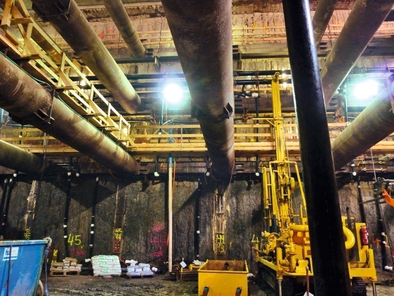
In the time frame available first of all advance drilling was carried out by two 380 mm drilling units using the direct flushing method from drilling level – 20.5 until roughly – 34. 0 m NAP and directly stabilised by means of DA 315 PVC pipes. The 390 x 315 mm annular gap was sealed with well dampers.
Then 2 light direct flushing drilling units were applied to reach the final depth of – 44.5 m NAP with advance groundwater pressure relief via the previously drilled wells. Fig. 5 displays an image of the drilling operations.
No flushing additives were applied. Once the final depth was reached and prior to the well lining material being installed the flushing agent was completely replaced by clear water. Thanks to the ongoing pumping operations and the pressure thus relieved in the intermediate sand layer it was possible to safely install the DN 100 high-grade steel water screen with 0.1mm slot widths and an installation length of 4.0 m.
The pipes for the wells were made of PEHD in order to avoid mechanical damage from earth-moving equipment during the excavation phase. The selected sleeve joints were pressure and vacuum tight.
The 300 x 100 annular gap between – 44.5 and – 39.0 NAP was filled with 0.2 to 0.5 or 0.4 to 0.8 mm fraction quartzite filter gravel depending on the filter convection. The application of this fine filter gravel and the water screen is extremely fragile and is a result of the existing ultra fine sands. An annular gap fill consisting of swelling clay as a flexible and effective advance seal between – 39.0 and – 35.0 m NAP succeeded just as well as grouting the remaining annular gaps with well dampers from – 35.0 m NAP to the bottom of the 2nd sand layer at – 26.0 m NAP. In this way the wells were designed to be pressure and vacuum resistant as well as made safe against mechanical damage through construction work in the pit.
Vacuum, Pumps and Control System
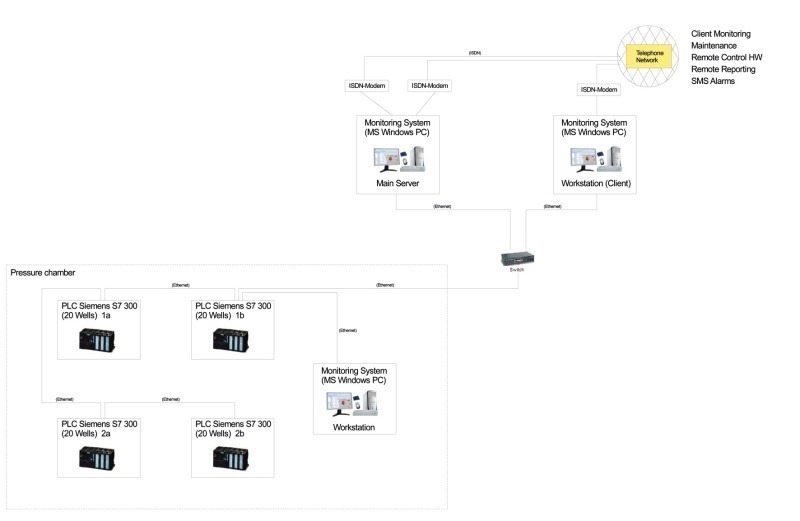
The groundwater management system was controlled via an PLC (Programmable Logic Controller) (Fig. 6) to ensure the best possible operating safety.
Submersible pumps were installed in the individual wells, which are suspended 1 m above the bottom of the well and can be switched on and off either via PLC or manually. Towards this end each pump is controlled individually. The notion behind this type of control system is to arrive at an as high as possible efficiency and avoid a number of pumps failing at the same point in time. The automatic control system is activated by the water levels prescribed for the individual wells that can be switched on and off, which are continuously measured by the pressure sensors integrated in the wells. In addition the water levels are measured by external gauges in order to check that drainage has attained the desired effect and that the theoretically calculated lowering can be confirmed.
In each case 8 wells are connected to a vacuum air pump for introducing the vacuum effect. The vacuum is created via suction pipes, which are connected at the well head, into the inside of the well and in this way transferred to the aquifer. Like the submersible pumps the vacuum pumps are controlled separately via PLC.
Risk Analysis, System Test and Minimising Risk
In order to be able to measure the groundwater management system under the complex marginal condition, relieving an ultra-fine sandy, thin-layered aquifer, a practical test was carried out in summer 2010. At selected points in the north and south of the excavation pit in each case 6 test wells were installed and set in operation. The execution of the test series with the types of wells and the process technology corresponded to the method employed for the groundwater management system for the entire excavation pit. On the basis of the pumping tests using different variations (with and without vacuum, various drainage targets and the water rising again) a groundwater model was created. Thanks to this finite element model different variants for groundwater relief were examined theoretically. Towards this end minimising risk was of particular significance. However to ensure that the economy of such a system and construction management as such were not neglected, as large as possible gaps between wells were chosen. A risk analysis accompanied the measurement programme. In this connection possible risk analyses were compiled in a complex matrix and evaluated. Furthermore just how these were to be measured and monitored was defined.
On the basis of the risk analysis for instance the redundance of the employed systems was called for. The fact that each well can be controlled individually provides the advantage that only one well is not functional in the event of a local disturbance. The vacuum effect is installed in such a way that the possibility of a series of pumps failing in the event of a faulty pump is eliminated. In this case only every 2nd well would drop out thus increasing the global safety against a series failing. In the event of a disturbance within the system alarm reports are sent to the responsible parties by SMS by means of the automatic control exercised by the PLC system. In this way the faster possible elimination of faults and a high safety level are achieved. In the case of total breakdown of the groundwater management system the compressed air system could cater for safety by temporarily increasing the overpressure. This temporary increase would however lead to a reduced working operating capacity for safety and health protection reasons.
Summary and Outlook
An efficient system operating at the highest level in safety technical terms for groundwater management was installed for the geological and hydrogeological marginal conditions in Amsterdam. Particular circumstances made it essential to find a solution suitable for the location. In inner urban tunnelling it is becoming increasingly more imperative to assure safety against direct or indirect effects thus preserving life, the environment and built-up areas: whether for example a hydraulic shear failure has to be prevented or groundwater levels outside excavation pits must be maintained in order to avoid undesired settlements or exerting a negative influence on urban vegetation. Towards this end consistent groundwater management and accompanying extensive investigation of the area affected by the construction scheme are imperative. Once the risks and priorities of a construction scheme have been determined an individualised, effective concept commensurate with the requirements can be devised.