Fire Tests for Water Mist Fire Suppression Systems
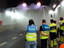
In May/June 2011 more than 30 major fire tests were carried out within the scope of the SOLIT2 project to establish the efficacy of water mist fire suppression systems in conjunction with the fire ventilation in road tunnels. The following report, presented on the occasion of the 2011 STUVA Conference in Berlin, shows the results that were achieved.
In May and June 2011 more than 30 major fire tests were carried out on water mist fire suppression systems in conjunction with fire ventilation in road tunnels to establish their efficacy for the SOLIT2 project. On a 1:1 scale the half of these fires were executed as pool fires with fire loads ranging from 30 to 100 MW; the others as solid matter fires involving complete lorry-loads (fire load 100 MW consisting of wooden pallets). In addition to checking the efficacy the interaction between the water mist fire suppression systems and other safety installations in tunnels was of particular interest in order to be able to identify possible savings potentials with the help of a holistic safety concept and develop practice-oriented solutions.
1 Introduction
The German project “Safety of Life in Tunnels 2” (SOLIT2) was started in 2009 with the aim of investigating the interaction between water mist fire suppression systems and other safety installations in road tunnels, as e.g. the fire ventilation. As the proven advantages of a fire suppression system incur additional costs as a pure extra installation, from the very onset the target was pursued to avoid increasing the costs for the entire safety installations in the tunnel. Instead the notion was to examine how other measures could be compensated for by means of a holistic approach.
Apart from developing and improving the process technology the project also embraced the development and validation of simulation tools for the mathematical-numerical appraisal of the interaction between water mist, fire and ventilation. The programme was rounded off by a holistic evaluation of the utilisation cycle costs as well as the compilation of a planning guideline.
The project was sponsored financially by the Federal Ministry for Economics and Technology as a result of a decision reached by the German Bundestag. It runs until 2012. In addition to the STUVA it involves the following partners: Fogtec Brandschutz GmbH & Co. KG, BUNG Ingenieure AG, the Chair for Tunnelling, Pipe Technology and Construction Management at the Ruhr University Bochum as well as TÜV Süd Rail GmbH. The fire tests were supported by the Institute for applied Fire Protection Research and the Fire Service Institute of Saxony-Anhalt.
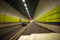
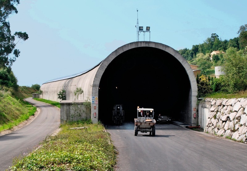
The findings obtained within the scope of more than 30 major fire tests in May and June 2011 in a test tunnel in Spain (Fig. 1) were of central importance for the project. Towards this end half of the tests were carried out as pool fires featuring fire loads of between 30 and 100 MW; the other half were solid matter fires with complete lorry-loads (consisting of a 100 MW “substitute fire load” of wooden pallets).
In the following the procedures of these major fire tests are explained and selected results presented.
2 Executing the Fire Tests
2.1 Test Tunnel Geometry
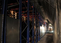
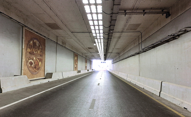
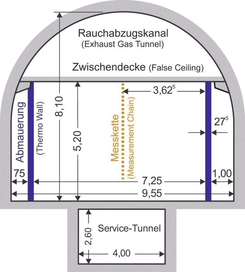
The fire tests were executed in the Spanish test facility “Tunnel Safety Testing” (TST) at San Pedro de Anes. The test tunnel available there possesses a total length of 600 m and is slightly S-shaped. It has a longitudinal incline of 2 ‰ and in its rough state possesses a horseshoe cross-section characteristic of road tunnels (9.95 m wide and 8.10 m high, Fig. 2).
In order to protect the concrete structure of the tunnel from excessively high temperatures in the fire zone, walls had to be set up at the sides restricting the test cross-section to a width of 7.25 m (Fig. 2). The test zone’s height was restricted to 5.20 m thanks to an intermediate ceiling protected by a fire protection plaster. The space above the intermediate ceiling was used as an exhaust duct for the semi-cross ventilation. Behind the walls at the sides there was room to install the extensive measuring and recording equipment.
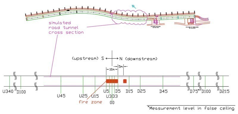
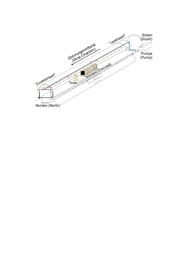
The middle of the fire load in the tunnel’s longitudinal direction was defined as 0.00 for all distance specifications. In the direction of flow measurement cross-sections included “D” (for “downstream”) and the corresponding metre number. Against the direction of flow measurements were undertaken accordingly with “U” (for “upstream”). A measurement cross-section, which for instance is set up 45 m behind the middle of the fire load, is thus designated as “D045” (Fig. 3).
2.2 Water Mist Fire Suppression System
For executing the tests a water mist fire suppression system was temporarily installed in the test zone over a distance of 60 m. Two rows with nozzles were attached to the intermediate ceiling in a longitudinal direction. The main supply line was fixed to the intermediate ceiling (Fig. 4).
The system’s water supply came from diesel-driven pumps, which were set up in a container outside the tunnel. The pumps operated at full capacity 30 seconds after being switched on. They were fed from a 500 m² large storage tank.
The system was first optimised regarding the types of different nozzles and their set-ups but then the parameters remained unaltered through the subsequent tests so that comparative results could be attained. The type of nozzle, the gap between the nozzles, the alignment of the nozzles (angle to the vertical), the gap between the pipes and the pressure on the nozzle furthest away from the pump remained unchanged.
2.3 Ventilation
The tunnel is fitted with a system for longitudinal and semi-cross ventilation. Longitudinal currents of 1 to 6 m/s can be accomplished with the jet fans attached to the ceiling. The optional semi-cross ventilation expels up to 120 m³/s via a ventilation station at the northern end of the tunnel above the intermediate ceiling (air speed of up to 30 m/s). Fourteen ventilation flaps are installed in the ceiling between the tunnel and the exhaust duct – each with a gross cross-sectional area of 1.5 m². The semi-cross ventilation is dimensioned for fires releasing up to around 30 MW of heat.
2.4 Solid Matter Fires (Lorry Fire)
The test set-up for a solid matter fire (100 MW) in each case consisted of 408 standard Euro wooden pallets. This corresponds to a weight of some 9t with a total energy content of 110 to 140 GJ. The fire load was roughly 10 m long, 2.40 m wide and 2.50 m high thus resembling a lorry-load. In the tunnel’s longitudinal direction it was set up symmetrically to the zero point (station U005 to D005).
Some of the solid matter tests were undertaken on a platform approx. 1.50 m in height, thus roughly corresponding to the height of a lorry’s loading area. The total height with fire load (H = 2.50 m) equalling 4 m corresponds to the height of a loaded lorry. Other solid matter tests were meant to simulate the situation in a higher tunnel (e.g. a tunnel with pure longitudinal ventilation and a correspondingly greater height). Consequently the fire load was placed on a platform only 0.20 m high. In this way an overall height of 2.70 m with fire load was attained. With the upper edge of the platform again representing the upper edge of the loading area, this corresponds to a tunnel height of 6.50 m (instead of 5.20 m as in the case of the other tests).
For the majority of the solid matter tests (11 from 15) the pallets were covered by PVC sheeting. On the one hand this reflected a realistic situation in road traffic during which a fire occurs on the loading area beneath the sheeting. On the other this represents unfavourable conditions for the water mist fire suppression system because the fire is protected from the water mist sprayed from above for a lengthy period.
In order to prevent the stack of pallets breaking apart prematurely during the combustion phase steel frames were used to hold them in position. The obstacle to the flow of air presented by the driver’s cab was simulated by a steel plate set in front of the pallets (in the oncoming air zone). In similar fashion the doors usually to be found at the end of the loading area were simulated by a steel plate.
In each case 3 fire trays were filled with 2 l of petrol. This corresponds to an ignition source of roughly 400 kW.
In order to discover whether a fire flashover occurs between 2 vehicles a stack of pallets was set up (“target”) at a distance of 5 m (at station D010) downstream – in other words in the direction of flow behind the fire load. This stack of pallets possessed the same height and width as the fire load (Fig. 4).
2.5 Pool Fires
Steel trays, which were filled with diesel, were used for the pool fires. Depending on the desired heat release rate (e.g. 30, 60 or 100 MW) a varying number of 2.5 m wide and 40 cm high trays were used (each roughly 2 to 4 m², in total e.g. 16, 28 or 51 m² surface area), which were filled with 330, 630 or 1,140 l of diesel. 1 l of petrol was additionally used per tray for ignition purposes.
2.6 Measurement System
During a fire test the relevant parameters were registered every 2 seconds with altogether 152 sensors in the tunnel. Depending on the test duration up to around 350,000 measurement values were recorded per test including:
• temperature
• heat radiation
• air speed
• gas concentration (O2, CO2, CO)
• pressure and flow rate of the fire suppression system
• air humidity
For each test the weather data outside the tunnel were measured. Prior to the solid matter fires the humidity of the fire load (wood) was established. Furthermore the temperature field and the visibility conditions were constantly determined through normal and infra-red recordings. Photos were taken to document the tests.
By and large the temperature measurements were employed to measure the air temperature. Some measuring points were set up so close to a surface (wall or intermediate ceiling) that the values obtained there (lying on the safe side) can also be interpreted as surface temperature. However the real temperature of the surface actually lay beneath the values measured in this manner. In order to obtain comparative values for the temperature development within a structural component, a concrete slab was attached beneath the tunnel ceiling approx. 7.5 m behind the zero position (roughly 2.5 m behind the end of the fire load for solid matter fires). Five temperature sensors were installed in this slab at 1 cm gaps. In this way it was possible to establish the time-related temperature development in the material at varying depths (approx. 1, 2, 3, 4 and 5 cm from outside/below).
2.7 Test Set-Up
When carrying out a fire test firstly the processing of the measurement data was activated and the ventilation system started and adjusted to the required flow speed. Subsequently the fire load was ignited.
For solid matter fires the water mist system was generally activated after 4 minutes. In this connection it was presumed that 2 minutes elapse between a fire breaking out until it is detected and a further 2 minutes until the water mist system is completely activated. In the case of pool fires the system was activated only 30 seconds following ignition of the last fire tray on account of the almost immediate fire development.
The fire duration and in turn the time period during which the fire could develop freely – influenced only by the water mist system – amounted to some 30 minutes. Then the fire was extinguished by the fire service. Only then was the water mist system switched off and the processing of the measurement data completed.
3 Evaluation of the Fire Tests
In the following the manner of working of the water mist system is explained taking the examples of 2 pool fires and 2 solid matter fires.
3.1 Pool Fire
In the case of the pool fires a “small” free fire (without the water mist system being activated) with a planned heat release rate of 30 MW was compared exemplarily with a “large” fire with a heat release rate of 100 MW in conjunction with the activation of a water mist system. In this way it was intended to show that a larger fire can be controlled when water mist is used even when more unfavourable ventilation conditions are prevailing.
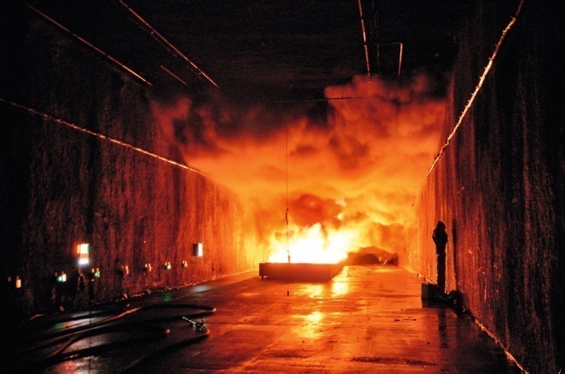
For both tests the longitudinal ventilation was set at roughly 3 m/s flow speed. In the case of the free fire (30 MW) the semi-cross ventilation was also activated: 120 m³/s of smoke gases were removed via the smoke extraction duct above the tunnel. When using the water mist system (100 MW fire) the nozzles were positioned 5.0 m above the carriageway. The water mist system was started 30 seconds after the last fire tray was ignited (Fig. 5). Table 1 contains the essential marginal conditions for the tests.
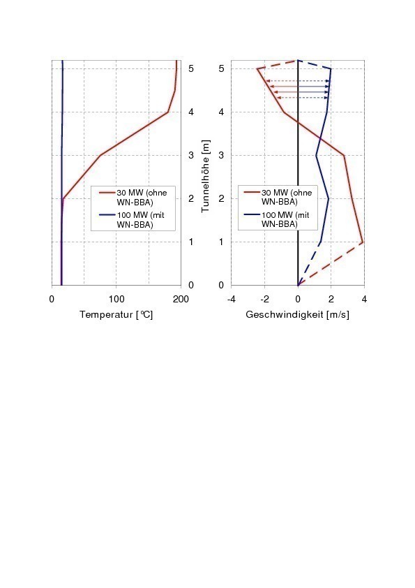
Even during the execution of the previously described tests it could be observed that what is known as “backlayering” occurred during the free fire (30 MW). In this connection hot fire gases moved against the longitudinal flow (“upstream”) and caused a thick cloud of smoke in the upper sector of the tunnel cross-section (Fig. 5). As a result the measurement values for the air flow revealed negative values in the upper sector 5 minutes after ignition and the measured temperatures amounted to just below 200 °C (Fig. 6). On the other hand the measurement values for the fire with activated water mist system (100 MW fire) revealed only positive speeds as well as low temperatures (approx. 15 °C, surrounding temperature). No backlayering could be observed in this case.
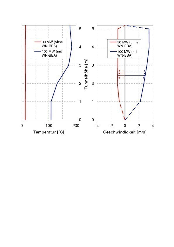
Shortly before the end of the test tunnel, 215 m behind the middle of the fire load, the application of the semi-cross ventilation has a role to play rather than the water mist system. Through the extraction of the smoke gases caused by the free fire (30 MW) outside air is also sucked in from the end of the tunnel. This is discernible from the negative speed values prevailing over the entire height (Fig. 7). As a consequence the temperatures correspond to those of the surroundings (approx. 15 °C).
During the test with water mist and only longitudinal ventilation (without smoke extraction via the intermediate ceiling, 100 MW) the hot fire gases must inevitably be blown out at the portal so that the nominal flow speed of about 3 m/s prevails here. Furthermore the air temperatures of 100 to 200 °C are higher than the surrounding temperatures outside the tunnel. Nonetheless the positive cooling effect of the water mist system is evident (Fig. 7).
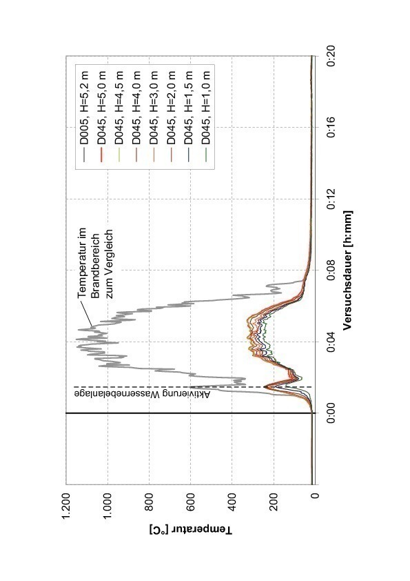
As an example the temperatures measured some 45 m behind the middle of the fire load (DO45) reveal the cooling effect of the water mist. If the hot gases at the fire source (DOO5) had still possessed temperatures of between 1,000 and 1,200 °C then temperatures of only a maximum of 300 °C would have been measured at DO45 (Fig. 8). Furthermore the fire in most trays would have been extinguished given the application of the water mist system although the entire fire load had still not burned.
3.2 Solid Matter Fires
For the solid matter fires an example is provided taking the form of a fire with the customary delay in activating the water mist system (4 minutes after igniting the fire load) compared with delayed activation of the systems (12 minutes after ignition. As in the case of all solid matter fires undertaken the scheduled heat release rate amounted to 100 MW. The height of the fire load amounted to 4.0 m (including the 1.5 m high platform). Both fire loads were covered with PVC sheeting.
The longitudinal ventilation was set at roughly 3 m/s flow speed for both tests. For the fire involving the customary delay in activating the water mist system (4 minutes after igniting the fire load) the semi-cross ventilation was additionally activated: 120 m³/s of fire gases was expelled via the smoke exhaust duct above the tunnel. The water mist system’s nozzles were positioned 5.0 m above the carriageway. Table 2 provides the essential marginal conditions for the tests.
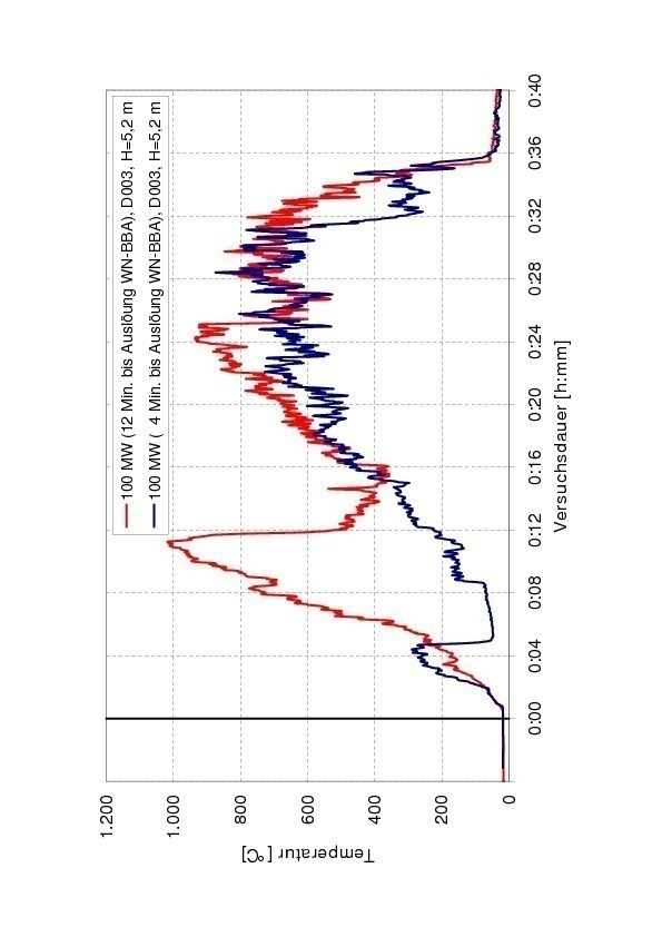
If one compares the temperature development beneath the intermediate ceiling directly in the fire load zone (3 m behind the middle of the fire load, DOO3) the time point of activation of the water mist system is clearly evident. In the test with the customary activation time (4 minutes) the temperature beneath the intermediate ceiling increases to almost 300 °C only to drop back to around 50 °C following activation. Qualitatively speaking the same temperature course can also be discerned in the case of the test with extended ignition duration. However the temperature beneath the intermediate ceiling increases to just below 1,000 °C until the water mist system is activated. After activation here too the temperature drops albeit as expected not so steeply as during the previous test – but “only” to around 370 °C (Fig. 9).
The temperatures presented in Fig. 9 beneath the intermediate veiling in the direct fire zone again regain values of between 800 and 900 °C several minutes after the water mist system is activated – following the previously described drop. These temperatures are however measured beneath the ceiling and can be explained by their direct contact with the flames. Consequently they cannot as such be taken to assess the efficacy of the water mist system.
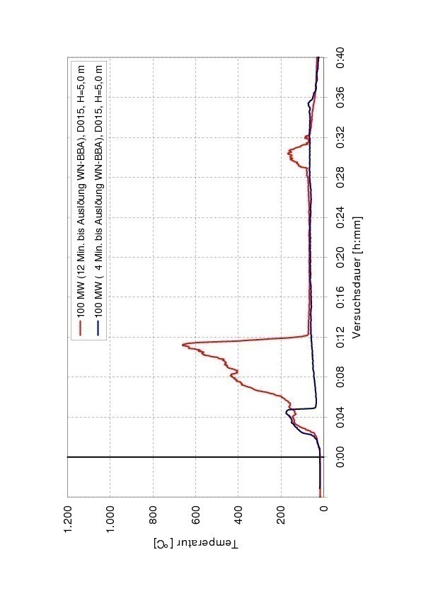
The positive effect of the water mist system in the cross-section 10 m behind the fire load (15 m behind the middle of the fire load, DO15, Fig. 10) can be recognised as clearer and more representative. After 4 minutes the temperature in the upper zone (at a height of 5 m, in other words 0.2 m beneath the intermediate ceiling) rises to 150 to 175 °C. After activating the water mist system (in the test with 4- minute ignition time) the temperature drops to roughly 60 °C. In the test with extended ignition period (12 minutes) the temperature first increases unchanged and at the time point when the water mist system is activated reaches about 650 °C. After the system is activated it drops rapidly to reach some 65 °C.
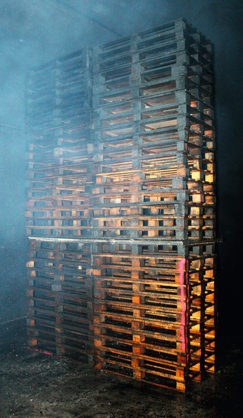
In addition to the measurement values obtained the target (stack of pallets, see above) set up 5 m away from the fire load also displays the effect the water mist system possesses in suppressing the fire. Both after the fire with a delay in ignition lasting 4 minutes as well as the fire with a 12 minute long delay in ignition the target was unharmed (Fig. 11) – only revealing traces of soot – although the fire load was almost completely combusted (in the case of the fire with a delay in ignition lasting 4 minutes 80 % of the pallets had burned, the remainder had largely been charred; the pallets had completely burned in the case of the fire with a 12-minute delay in ignition).
3.3 Assessing the Results
The presented test results reveal that a water mist system can positively influence the development of solid matter fires as well as pool fires. In both cases the water mist has a cooling effect on the fire load and on the environment so that the temperatures increase less rapidly. This effect makes itself felt first and foremost a few metres behind the fire load (in the direction of flow). In this way the danger of fire flashing over to other vehicles – as the “targets” showed – is reduced to a great extent. Furthermore the lower temperatures around the fire first make it possible for the fire service to tackle the blaze.
Generally it is important to activate the system as soon as possible so that the positive cooling effect sets in at an early stage. In this way structural damage resulting from temperature is confined to a relatively small zone or even totally avoided. In this connection the size of the fire load (e.g. 100 MW) represents only a subordinated criterion in assessing the outcome.
It was observed in particular in the case of the described pool fires that through the application of the water mist system the development of smoke could be considerably reduced. Thus obvious backlayering occurred in the case of the fire tested carried out with 30 MW energy release rate and activated semi-cross ventilation (smoke removal via the intermediate ceiling) – but without the application of a water mist system. Backlayering could be prevented also in the case of a fire with 100 MW energy release rate even without semi-cross ventilation. This clearly shows that when a water mist system is applied even fires for which the existing ventilation is not designed can be mastered.
4 Summary and Outlook
Within the scope of the SOLIT2 research project more than 30 major fire tests were carried out in May and June 2011. Altogether some 6,000 Euro pallets for solid matter fires and approx. 8,000 l of diesel for pool fires were burned. 1,200 m³ of water was used for operating the water mist fire suppression system and for the extinguishing operations tackled by the fire service.
With the help of the executed tests firstly the efficacy of water mist fire suppression systems in road tunnels could be reconfirmed. Secondly important data were gained by means of which the development of mathematical-numerical models to simulate the complex processes involved in applying water mist in fire zones could be construed. Thirdly real data were obtained, which can be used for assessing compensation possibilities when applying water mist systems.
The tests have revealed that through applying water mist systems external rescue is supported by enabling even very large fires (e.g. 100 MW) to be approached. Thus efforts to extinguish the blaze on the part of the emergency services are effectively supported or made at all possible in the case of major fires.
The positive test results confirm that the compensation potential strived for is technically available. The financial evaluation of compensation within the scope of a life cycle cost calculation will take place within the next few months.