Influences on Segment Damage
Damage to segments is frequently associated with time-consuming and in turn correspondingly cost-intensive repair work. Such repairs hamper work progress and exert negative effects on the outcome of the project. The effects can be reduced if the individual influences on segment damage are identified and in turn avoided.
1 Introduction
Segments represent the bearing structure for the finished product in mechanised tunnelling. This fact results in high demands both on manufacturing as well as on transporting and installing the segments. The segments must be dimensioned to cope with the geostatic as well as the specific driving loads that occur. Local overstressing results in damage to segments. This causes cracks, spalling and leakages, to repair which can be both time-consuming as well as cost-intensive. Thus it is essential during the entire development process, from manufacturing the segment to its installation, to minimise the damage quota. The occurring damage can be divided into internal and external influences as far as the cause of damage is concerned.
2 Internal Influences
Care should be taken during manufacturing to ensure that the formwork corresponds to the high demands placed on the precise form of the segments. Should the formwork not correspond to the segment dimensions applied during planning and computation then all the segments cast in this formwork are incompatible with planning. The precise form of the entire ring fails to exist in this case so that stress peaks arise locally, which result in spalling and cracks. The ZTV-ING provides tolerances for this, which must be applied during the calculation stage as well as adhered to during manufacturing. Thanks to a regular inspection of the segment formwork as well as the concreted segments it must be assured that these tolerances are adhered to during manufacturing and that the precise form of the segments is arrived at.
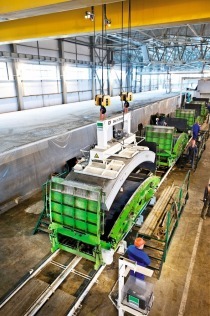
Apart from the precise form the concrete quality used during manufacturing is decisive. As precast concrete parts with special demands segments are subjected to stringent monitoring. It is easy to adhere to the basic conditions governing quality in stationary manufacturing plants although permanent supervision is essential (Fig.1).
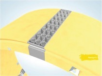
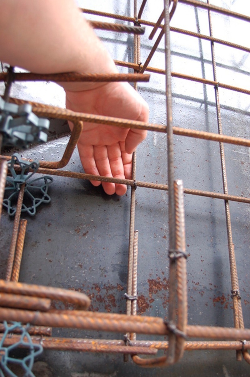
The nature of the concrete depends on the concrete quality and to a particular degree on the quality and the correct position of the reinforcement baskets. Considerable experience and extensive knowledge of detail are necessary for calculating and producing reinforcement baskets. When placing the baskets in the formwork the utmost care must be taken to avoid inaccuracies in positioning. Spacers, which are firmly attached to the baskets, serve as aids for positioning the basket in the formwork. It is advisable not to use plug-in spacers for segment production as they tend to fold so that the required positional accuracy cannot be assured (Fig. 2). Intensive monitoring is called for here.
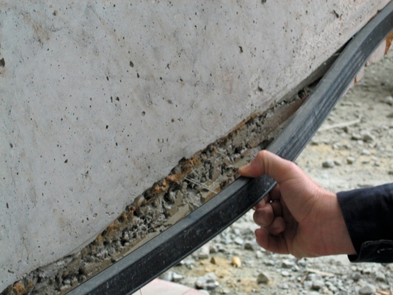
In keeping with the consistency and workability of the segment concrete the compaction energy has to be regulated. Compaction largely ensues via external vibrators. Care must be taken to ensure that air pores are completely eliminated particularly in the sealing area otherwise the sealing gasket can quickly become negatively affected (Fig. 3).
3 External Influences
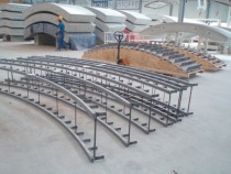
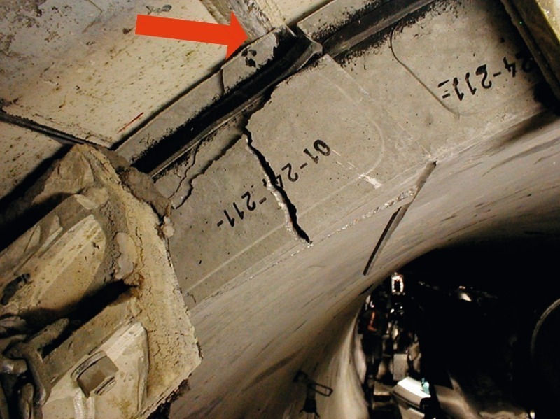
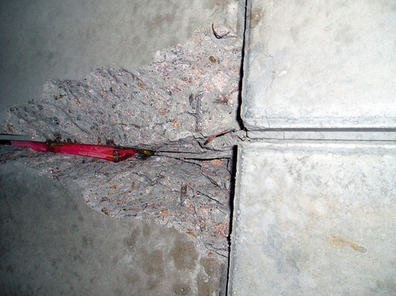
External influences primarily are linked to faults during installation. If the segments are not placed in the exactly predetermined position during installation of the ring, the outcome is displacements in the segment joints. These can occur both in the longitudinal joints within a ring as well as in the annular joints between 2 rings (Fig. 4). Permissible tolerance ranges are defined in advance. If these tolerance ranges are exceeded during the construction phase, the tunnel’s tightness is principally affected as the seals for the individual segments no longer sufficiently overlap. Furthermore the load transference areas diminish thus also leading to an increase in the stresses within the segment. The reason for such displacements is largely connected with a lack of experience or training of the staff concerned. If workers are instructed properly this is easily be rectified and a rapid learning curve can be anticipated.
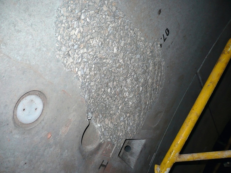
A further typical defect characteristic is concrete spalling at the erector guides. A standard segment generally possesses a conic frustum-shaped indentation in the middle of its inner side in addition to fixtures for dowels and/or bolts. The erector plate is provided with a centring cone, which fits into this indentation on the inner side. In this way it can be assured that the erector plate is in the correct position, when it sucks and lifts the segment via vacuum. If the erector plate’s vacuum is released the erector guide (erector cone) can come into contact with the segment in the event of shear stress. Frequently the concrete edge breaks off at this point (Fig. 5). As the erector operator gains experience he will use the jacks to push the segment sideways and hold the erector plate centrically above the recesses. In this way harmful contact between the erector plate and the segment is avoided.
Once the segment is set in the correct position, the driving jacks retracted for constructing the ring are applied to the segment again. The segment gaskets must be pressed together to attain
tightness. The erector is not capable of providing the required force on its own. The driving jacks must also apply pressure. Once the sealing gaskets have been sufficiently compressed the segment is bolted together with its surrounding stones. The bolts that are applied should maintain the primary tension until it is adequately embedded. Generally roughly 15 further rings have to be installed before the bolts can be removed. The necessary compressive force is generated by the so-called ring construction pressure of the driving jacks. Should this be inadequate, e.g. because the TBM lurches forward while installing the rings, the bolts must essentially be tightened during the next driving sequence. If the sealing gaskets are not sufficiently compressed, leaks can occur, which have to be subsequently repaired – not an easy task.
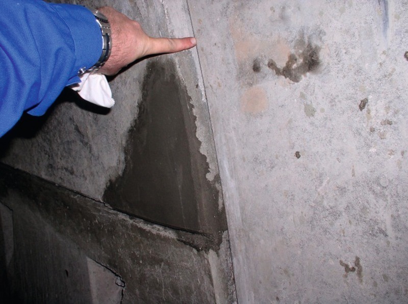
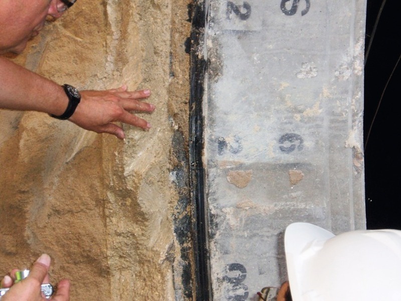
For the choice of the ring to be installed it is necessary to pursue the principle that ring construction must always follow up the passage of the TBM. Should for example the TBM drive towards the right, no rings possessing orientation towards the left can be installed. If this principle is not observed, contact between the installed ring and the machine’s shield tail ensues. Should this occur the outside of the segment is destroyed and usually its front side as well (Fig. 6). As the sealing zone is located on the outside, a complicated repair is involved. The front side of the segment must be checked prior to installing the new ring to identify such points of damage.
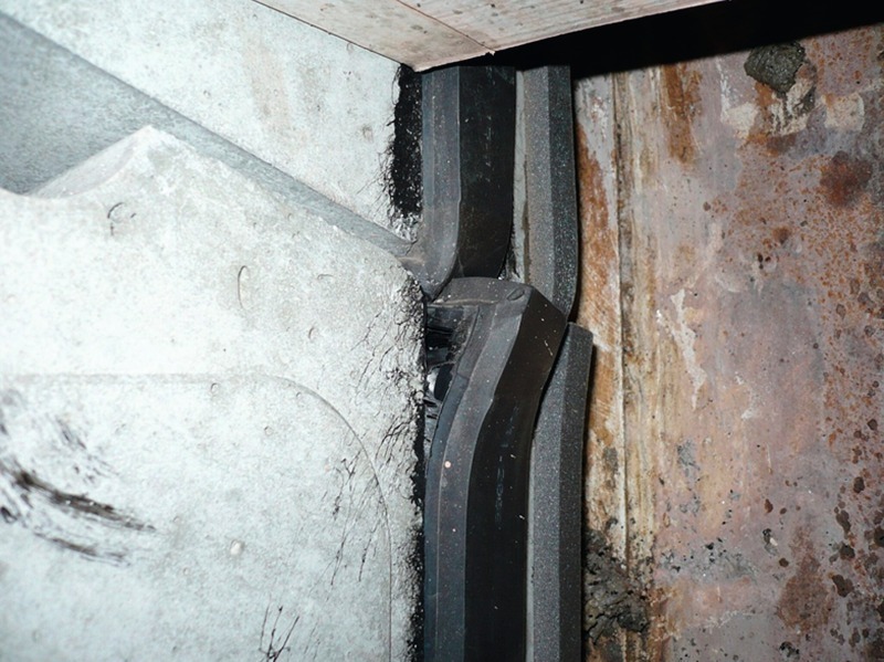
Furthermore it can be observed that the gasket slips out at the side in certain cases when the keystone is put in position. Two typical causes come in question for the type of damage. First of all the ring can be installed in such a constricted manner that the keystone does not fit into the available gap. Owing to the fact that the keystone must be pressed intensively into the gap, shear stresses result between the sealing gaskets and the segments, which can no longer be sustained by the adhesive with which the gaskets are attached to the segments (Fig. 7). Special attention must be paid to the shield tail air in this respect. Secondly excessively high frictional forces, which can also occur between the gaskets even if the ring construction procedure is undertaken perfectly, can be the cause. A solution is to smear the gasket with lubricating soap.
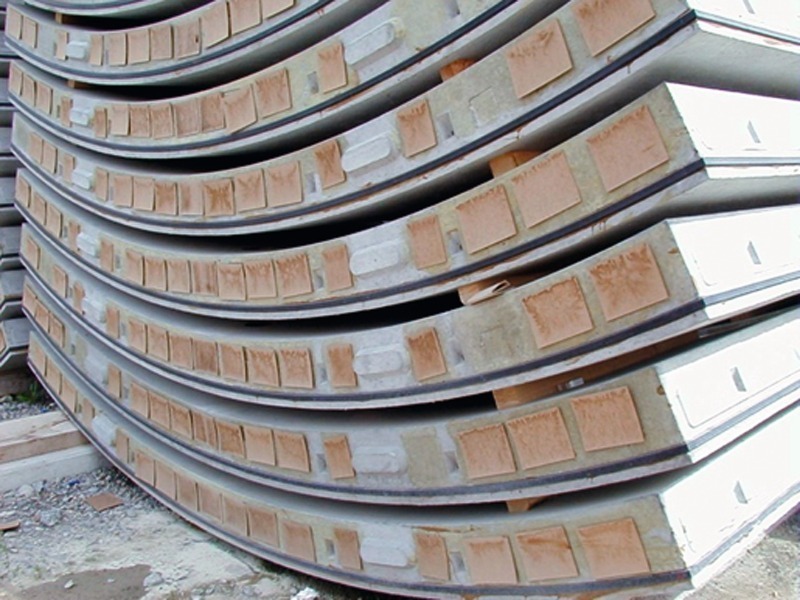
Currently the need for load distribution plates consisting of PE, bitumen or hard fibre is subject to controversy. Installing such load distribution plates (Fig. 8) basically fulfils 2 tasks. First of all it is aimed at avoiding a concentration of the driving loads at the centre of the segment and ensuring that the entire thickness of the segment is utilised for uniformly sustaining the load. Secondly minor segment cants are compensated for in this way, without creating direct stress peaks. Regardless of the still ongoing discussion it can be maintained on the basis of the findings obtained from many projects that the damage quota could be substantially reduced in the case of the subsequent introduction of load distribution plates.
Manually placing wood fibre plates e.g. in the annular gaps to compensate for an uneven ring level is described as packing. Compensating for cants would require an exact allowance and then adapted distribution of the inserts. So far there is no tunnel drive known to man in the case of which the packing was executed with such a degree of care that a lasting improvement was attained. On the contrary there are many examples, where considerable damage first ensued following the independent, unscheduled decision to insert wood fibre plates (Fig. 8). Packing is thus contra-productive in practice. Generally the ring construction crew should not be allowed to select material and thickness independently in the first place.
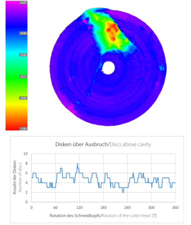
Apart from the loads generally exerted on segments by the driving jacks, which can lead to damage, it is also essential to take radial loads resulting from grouting and the rock into account. The grouting mortar must facilitate the ring to be embedded uniformly and is partially applied statically for this purpose. Towards this end it is essential that the grouting mortar is evenly distributed around the ring (Fig. 10). In the case of water impermeable soil the removal of water ultimately leads to uneven bedding and possibly to damage. Two-component mortars are advisable for this kind of soil in general.
To round off the picture damage resulting from rock deformations is touched upon. In soft grounds rock deformations very seldom lead to the segments being overloaded as the load distribution is substantially simplified. Through the vault effect in such soils generally speaking a uniform load for the segmental shell ensues.
For hard rock drives on the other hand depending on the nature of the rock (e.g. fissuring) highly varying and quickly changing load states can act on the tunnel support. As a result this type of load must be lent far greater consideration during planning and execution in hard rock.
4 Summary
Damage occurring to segments can effectively be split up into external and internal influences. By means of regular monitoring and testing of production, damage resulting from internal influences can be avoided during the manufacturing process. External damage effects largely occur during transport and when the segments are being installed. Such influences can usually be minimised through adopting care during handling and installation. For ring construction the crew should be provided with sufficient time, especially at the beginning of the project, to facilitate a rapid learning curve as devoid from faults as possible.