Crossing the Ems near Emden/D
Currently an approximately 4 km long tunnel is being produced to the west of the town of Emden/D, which will cross the River Ems in the direction of the Netherlands. The aim of the tunnel is to carry a 48 inch gas pipeline. The following report examines the constructional and logistical measures required to accomplish the scheme.
The BCE Joint Venture, consisting of Wayss & Freytag Ingenieurbau AG, Frankfurt am Main/D, and the Dutch BAM construction company, was commissioned to construct the tunnel in summer 2008. The client is the Nederlandse Gasunie, which is also based in the Netherlands. The new gas pipeline is needed to adjust transportation of gas in Europe to future requirements and circumstances.
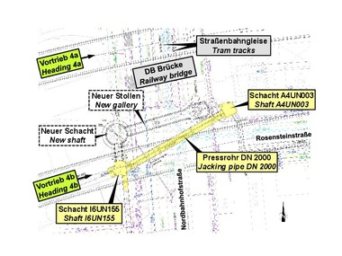
The tunnel will be exactly 4,016 m long. It crosses below the Ems from the German centre of Knock finishing up at the Dutch town of Borgsweer (Fig. 1). The Ems shipping channel is 12 m deep at the tunnel crossing. Taking this dimension into account as well the geological conditions the tunnel axis is located 23.5 m below sea level in the vicinity of the shipping channel. The tunnel’s maximum gradient amounts to 5 % shortly after the starting shaft located on the German side.
Geology
The tunnel route in the Ems estuary zone lies in various friable, cohesive and organic soft ground deposits originating in quaternary, glacial and post-glacial periods (Fig. 2). The soil overburden above the tunnel ranges from 4 m at the target shaft to some 17 m on the Dutch bank of the Ems. The gap between the tunnel roof and the bottom of the Ems amounts to approx. 11.5 m.
Extensive erosion channels, which are filled with sand, silt and clay, were created during the Elster ice age. During the subsequent Saale ice age, these Elster ice age sedimentations partially eroded with first and foremost sands and occasional cohesive boulder soils being deposited. This was followed by the partial erosion of the older Pleistocene deposits during the Weichsel ice age so that deep meltwater drainage channels were produced in them, which filled up with meltwater sands of varying compositions as well as local layers of gravel during the course of the Weichsel ice age and on account of the general rise in sea level and groundwater.
During the post-ice age the coastline was displaced land inwards as a result of the ongoing rise in sea level and watt sands with in some cases clay layers sedimented on top of the older Pleistocene deposits. Organic soft strata derived mainly from moor and marsh formations with occasional sand layers were deposited on top. In the course of the evolution of human settlements in the Ems estuary zone in some areas artificial elevations of the terrain such as e.g. landfills for industrial estates and dikes were created, which extend to above the high-water mark of the Ems.
In the Holocene and Weichselian sands of the Emsmarsch the groundwater is largely artesian on account of the overburden bearing soils that do not conduct a great deal of water. This is connected in hydraulic terms with the water table of the Ems, which is subject to fluctuations in conjunction with the tide. The groundwater and hangwater in the Elster ice age sands beneath the Lauenburg Clay that confines the groundwater are also artesian. The maximum water pressure amounts to roughly 3.0 bar at high-water mark.
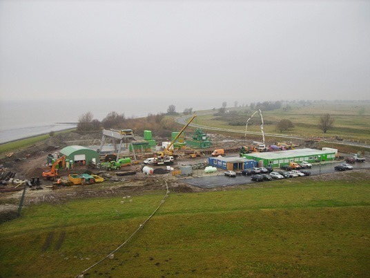
Construction Site Installations
Work on setting up the site installations on the German side started in September 2008. The area directly at the Ems provided by the client is large enough to accommodate all the components required for the excavation (Fig. 3). The starting shaft with a maximum depth of 8 m comprises piling walls and an underwater concrete base and was completed in December 2008 (Fig. 4).
The engineering installations needed for the drive such as the separation plant, bentonite mixing plant etc. were set up on site according to schedule and tested. The TBM is supplied by means of diesel locomotives. A total of 3 locomotives are foreseen for the drive. They are made by Schöma and each has an output of 75 kW. It is planned to provide the tunnel with a passing point for trains when they encounter each other.
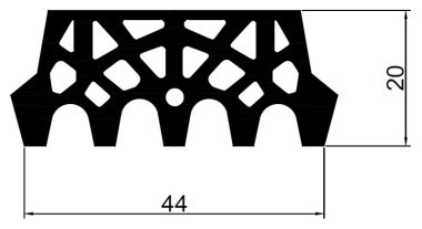
Segments
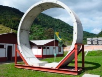
The tunnel is lined with the aid of segments. After searching for the most efficient solution for the cross-section and the reinforcement it was decided to select a tunnel internal diameter of 3.0 m.
A ring comprises 5 segments, which are 1.2 m wide and 0.25 m thick. Uni rings with a conicity of 30 mm each were produced to enable space curves to be driven and compensate for driving tolerances. It was decided not to choose conventional reinforcing with steel bars but to apply steel fibres. The “ZTV-ING Part 5 Tunnelling Section 3 mechanised Shield Driving Methods” was selected to establish the target value for the accuracy of the segments.
Production of the segments started in September 2008 at Rekers in Spelle/D. The carousel there is capable of securing the demand for the segments on site with 6 moulds. The segments are transported per rail to the temporary depot at Emden (storage capacity approx. 150 rings) and then by lorry to the site. A maximum storage capacity of some 120 rings is foreseen on the site installation yard. A further back-up supply of no less than 800 rings is available at the factory in Spelle if need be.
Tunnel Boring Machine
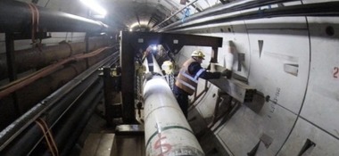
The TBM generally reconditioned by the BCE Joint Venture (Fig. 5) is 12.68 m long. The external diameter at the cutting wheel amounts to 3.78 m. The trailers are completely new and are altogether roughly 80 m in length (Fig. 6). The segments are delivered to trailer 5 of the back-up system where they are lifted from the train with the help of a rapid unloading device. From this point the segments are transported by monorail individually to trailer 3 of the back-up and set down on the feeder. The segment feeder carries the segments beneath trailers 1–3 to the erector, which lifts the individual segments into position thus creating a ring. A total of 11 driving jacks subsequently support themselves against the segmental ring (Fig. 7).
The TBM is devised for hydro-shield drive in accordance with the geological conditions described under the section dealing with “Geology”. A bentonite suspension subjected to pressure in the extraction chamber is applied to effectively support the face. Together with the excavated material the suspension is pumped to the starting shaft on the German side. A separation plant designed by Wayss & Freytag for the prevailing soil is located there. It separates the excavated material from the suspension (Fig. 8). The suspension is prepared and used again. The muck is dumped close to the construction site.
Outlook
Once the site installation yard is equipped with all the necessary components the excavation is due to commence in the spring of 2009. Ten months later the gas pipeline will be put into position providing everything works out favourably. The tunnel will be completely backfilled prior to it being commissioned, which means there is no intention to ensure the tunnel remains accessible nor service the external jacket of the pipeline. All going well gas will be transported through the line in September 2010.