Tunnels to Bad Cannstatt – Undercrossing a Long-DistanceHeat Pipeline at Difficult Conditions
 Credit/Quelle: WBI
 Credit/Quelle: DB PSU
 Credit/Quelle: WBI
 Credit/Quelle: WBI
 Credit/Quelle: DB PSU
 Credit/Quelle: WBI
 Credit/Quelle: WBI
 Credit/Quelle: WBI
 Credit/Quelle: WBI
 Credit/Quelle: WBI
 Credit/Quelle: WBI
 Credit/Quelle: DB PSU
 Credit/Quelle: DB PSU
During construction of the Stuttgart 21 railway tunnels leading to Bad Cannstatt a shaft and a 2-m-diameter jacking pipe of the long distance heat supply were unexpectedly encountered. At first, the tunnel heading was continued underneath the structures of the energy supply company EnBW. Then, it had to be investigated how the railway tunnels could be relocated into their final position according to design, without interrupting the heat supply. A first option was to relocate the heat supply pipe towards north, between the two railway tunnel tubes. Due to conflicts of aims, this solution had to be discarded shortly before completing its detailed design. Finally, a solution was realized, in which the heat pipeline was secured by additional measures and then undercrossed by the railway tunnels with a flattened roof.
1 Project and Problem
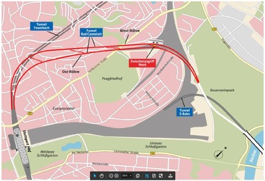
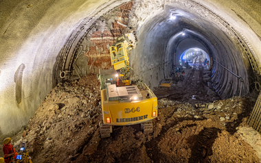
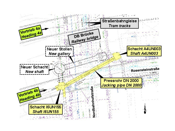
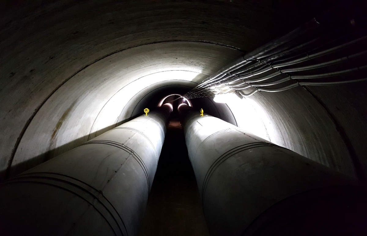
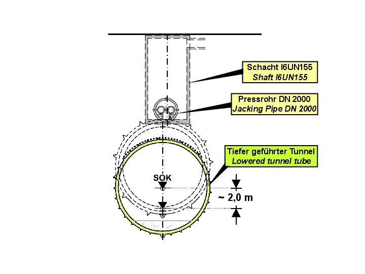
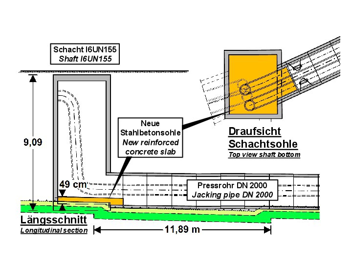
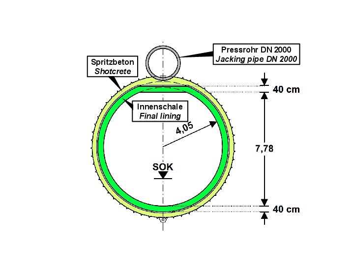
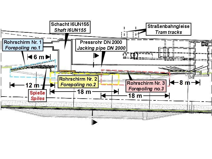
In connection with the large-scale railway project Stuttgart 21, the two tubes of the long-distance railway tunnel leading from the main station to Bad Cannstatt were built. During construction of these tunnel tubes, when drilling the pipe umbrella, a shaft and a 2-m-diameter jacking pipe of the long-distance heat supply of the city of Stuttgart were unexpectedly encountered in the roof area of the tunnel cross-section (Fig. 1). Within the jacking pipe, two main pipelines with 60 cm inner diameter are running from shaft I6UN155 to shaft A4UN003 and undercrossing as a culvert the street ‚Nordbahnhof‘ as well as numerous supply lines and the city’s tramway (Fig. 2). Since it was not possible to interrupt the operation of the heat supply pipes, the railway tunnels were at first constructed underneath them. Towards this end, the railway tunnels were temporarily lowered on an approx. 50 m long section. The tunnel construction in this section was carried out with forepoling as in the regular tunnel sections (Figs. 3 + 4).
Subsequently, it was necessary to develop a solution how to relocate the railway tunnel tubes into the final position according to design. It was a mandatory condition not to interrupt the operation of the long-distance heat supply.
2 Re-Location of Pipeline with Construction of New Shaft
2.1 Conditions in the Center of the City
First, a preferential solution was elaborated according to the specifications of the owner of the distance heat supply, EnBW (Energie Baden-Württemberg AG). In this solution, the heating pipeline was to be relocated to the north between the two tubes of the new long-distance railway tunnel. For this purpose, a new shaft was to be constructed, from which a gallery was to be driven towards east and connected to the existing structure (Fig. 1).
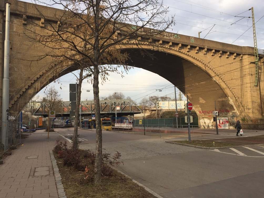
For the planning, numerous consultations had to be conducted with EnBW and other parties involved in the project and affected by the solution. These are different entities operating the gas, water and electricity utilities, as well as the Stuttgart municipal drainage system and numerous telecommunication providers. In addition, a section of the Stuttgart tramway “SSB” running in ‘Nordbahnhof’ street had to be undercrossed and would have been directly affected by the planned measures. Furthermore, the new shaft affected an existing bridge of the German Railway, which is located adjacent to the area in question (Figs. 1 + 5).
The required excavation pits would also have had a direct impact on the public traffic so that they had to be coordinated with the city of Stuttgart. The traffic routing, which is special at this location anyway, also includes a main cycle route. Under these difficult intra-urban conditions, the re-location of the pipeline with the construction of a new shaft had to be planned as specified by the owner of the line in December 2016.
2.2 Conflicts of Aims
In the course of the detailed design, it became apparent that there were numerous conflicts of aims between the various involved project participants, which could not be resolved easily. For example, the re-location of the telecommunication lines required for the planned shaft construction led to further interventions in the gas, water and electricity sectors. On the other hand, a relocation of the shaft structure to avoid the numerous conflicts with the utility owners resulted in a conflict of objectives with the existing railway line and the SSB facilities.
The possible location of the new shaft structure resulting from the investigations and the associated site installations would have required the diversion of all traffic routes and was therefore rejected by the city of Stuttgart.
Despite these constraints, the detailed design for the solution specified by EnBW was largely prepared by the German Railway entity DB PSU together with WBI. However, as new difficulties repeatedly arose during the planning process, the solution did no longer seem to be completely feasible after a certain time. After numerous rounds of coordination with, among others, the utility entities and the transport authority of the city of Stuttgart, the DB PSU therefore decided in September 2018 to resume talks with EnBW about an alternative solution.
3 Variant: Securing the Existing Heat Pipeline 3.1 Coordination with EnBW
In an early design phase, a variant was considered in which the existing heating supply pipes were to be secured in their current location. However, this variant had been rejected by the EnBW company due to the associated intervention in their facilities. Against the background of the difficulties in relocating the pipeline, the discussion about the variant of securing the existing pipeline had to be re-opened. The group of participants could be limited to EnBW, DB PSU and WBI. Due to the meanwhile time-critical project schedule, the meetings had to be held in close succession.
Since the bottom of the shaft I6UN155 and of the adjacent 2-m-diameter jacking pipe interfere with the clearance and excavation profile of the tunnel, it was unavoidable to take measures at these structural components (Fig. 4). For this reason, this variant was rejected by the EnBW company in several meetings. Finally, WBI succeeded in optimising the solution in such a way that the remaining restrictions in the area of the culvert were acceptable for EnBW. With regard to the constructability, the DB PSU involved the joint venture of construction companies as advisory capacity in this phase. After intensive efforts of all parties, EnBW finally gave its approval for the optimised version of the heat pipeline protection in April 2019.
3.2 Measures in Existing Structures
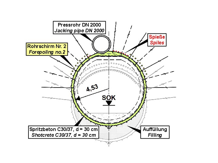
The detailed design was immediately completed by WBI. The designed measures included a stepwise demolition of the existing shaft bottom. The shaft walls were underpinned and a new reinforced concrete floor was installed in a higher position in the shaft – but still below the existing 60-cm-diameter steel pipes – and in the first section of the jacking pipe (Fig. 6). Further permanent interventions in the jacking pipe were not permitted. Therefore, it was necessary for geometric reasons to flatten the roof of the long-distance railway tunnel tubes in the critical area (Figs. 6 + 7). The joints between the pipe sections of the jacking pipe were temporarily secured as a preliminary measure for the construction of the final roof area of the tunnel.
The works had to be carried out while the heat supply system was in operation. It was therefore not possible to dismantle the EnBW installations. The entire delivery, including the supply of steel and concrete, had to be carried out through the opening of the shaft I6UN155. This opening was therefore extended to a rectangular opening of 1.5 x 1.5 m. Due to the location in a traffic area, the available room for site installation was very small. Furthermore, the working area was only accessible via a ladder. An additional aggravating factor was the temperature of permanently more than 30 °C due to the operation of the heat supply. Therefore, a corresponding safety and health concept had to be elaborated for the works at the existing structures.
It was important to start works in the middle of summer 2019, as sections of the 60-cm-diameter steel pipes of the heat supply had to be replaced in advance. This work could only be carried out during summer outside the heating period. Therefore, delayed design would have resulted in a construction delay of about 9 months. The coordination of the execution was carried out in close partnership with EnBW. The design of the line protection proved to be well realisable. This was also ensured by the flexibility of the JV Tunnel Cannstatt, responsible for the construction work. The pipeline protection measures in the shaft and jacking pipe were started in August and could be completed in November 2019.
4 Construction of the Final Roof Area of the Railway Tunnel
4.1 Design for Minimizing Settlements
After carrying-out the securing measures in the shaft and jacking pipe of the heat supply, the railway tunnel tubes could be relocated into their final design position. Due to the existing facilities in the ‘Nordbahnhof’ street, the construction of the final roof area of the tunnel had to be carried out with minimum settlement. In particular the components of the heat supply, the tracks of the tram and the gas pipes located along the road were very sensitive in this respect. Furthermore, it had to be ensured that the stress redistributions and the resulting displacements in the subsoil would not cause inadmissible stresses on the 2-m-diameter jacking pipe.
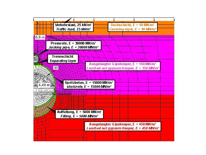
Therefore, WBI elaborated a solution for constructing the final roof area, in which as a first step a bottom filling and a shotcrete invert were installed in the lowered tunnel section. The construction of the roof area was then carried out with short cut-off lengths. In every cut-off, the shotcrete support in the vault area was connected to the shotcrete membrane in the invert. In this way, an early ring closure was always achieved, which is decisive for minimising settlements. The statical verifications were carried out on the basis of numerical calculations using the finite element (FE) method (Fig. 8).
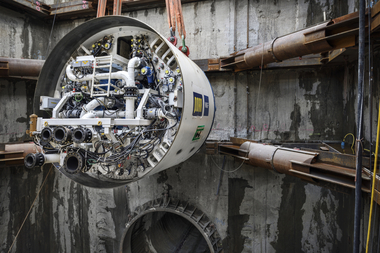
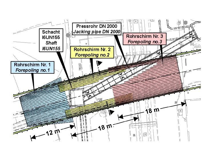
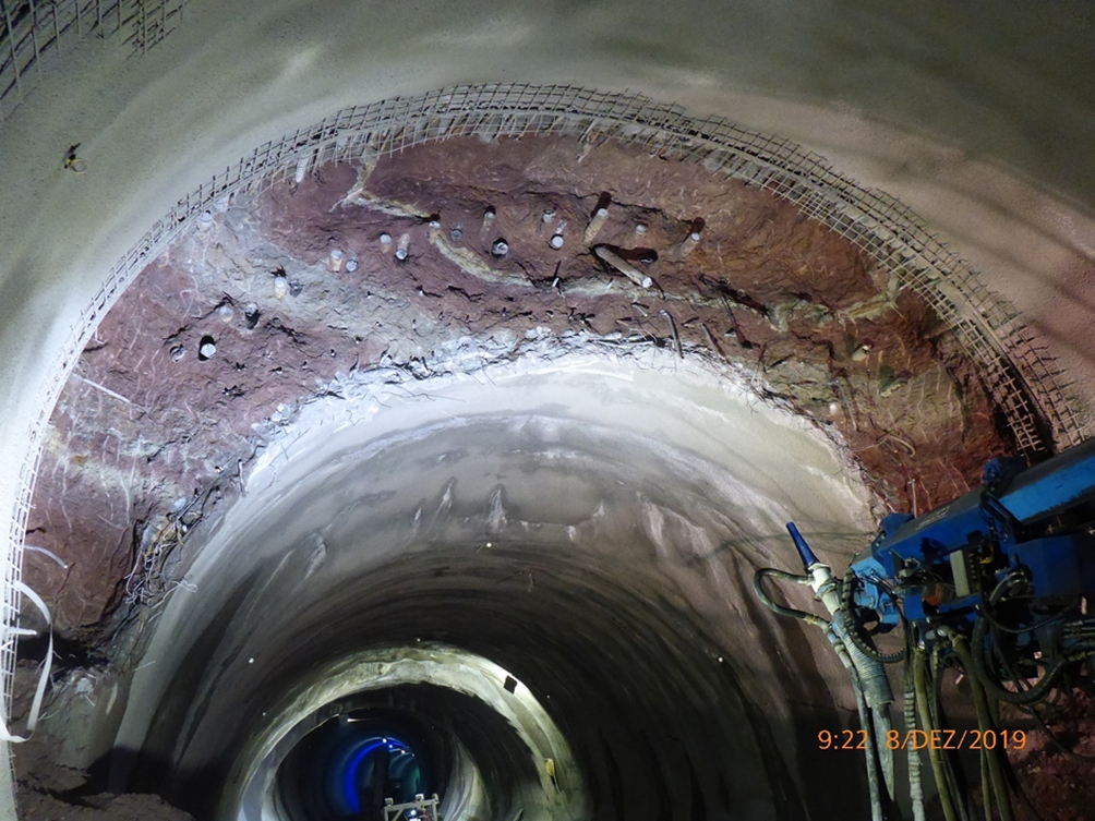
A total of three pipe umbrellas (forepoling) were foreseen as advancing support. Pipe umbrella 1 was constructed in the west from an existing niche with an inclination of 13° against the tunnel axis up to shaft I6UN155. Then, two 6 and 8 m long niches were excavated under the protection of spiles. Starting from these niches, the pipe umbrellas 2 and 3 were installed from the west and east respectively with an inclination of 1° (Figs. 9 + 10). The forepoling pipes of pipe umbrella 2 had to be omitted in in the area of the shaft in the roof sector. Moreover, in order to avoid damaging the components of the heat supply, the lengths of the forepoling pipes had to be partially adjusted. In the corresponding sections, the advancing roof support was provided by the installation of spiles (Figs. 9–11).
4.2 Execution of Construction
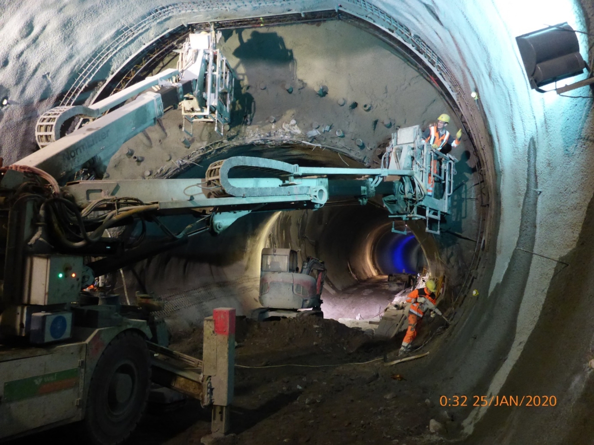
The construction was carried out between November 2019 and January 2020 and involved the demolition and removal of the support elements, which had been installed during the initial tunnel driving at a lower level (Fig. 12). Additional challenges resulted from the short cut-off lengths of 50 cm only and from the combination of different excavation support measures with forepoling and with spiles in the area of the shaft (Fig. 13).
The dismantling of the shotcrete membrane proved to be particularly sound transmitting. Therefore, the client DB PSU offered overnight accommodation to the residents affected in the immediate vicinity during the construction works.
Irrespective of the unusually difficult and special boundary conditions, the construction of the definitive roof area of the railway tunnel tubes was successfully executed in accordance with the approved design between November 2019 and January 2020. The admissible limits for the displacements in the tunnel, in the components of the heat supply and on the ground surface were met.
5 Conclusion
The construction of the internal lining blocks with flattened roof and special formwork was completed in June 2020. Thus, including the retrofitting measures in the existing heat supply system, the total construction time was less than one year.
Compared to the originally preferred option of re-locating the pipeline and constructing a new shaft, which was extremely difficult to realize due to the boundary conditions, the executed solution achieved significant economic advantages. The construction time could be reduced by approx. 9 months. For the project participants, the re-design thus turned out to be a success.