Design and Construction of Tunnels in Jointed Rock according to the AJRM Method – Part 1
For a safe and economical design of structures in jointed rock, a realistic consideration of the interaction between rock mass and structure is required. This requirement is neither fulfilled by the subgrade reaction method nor by classification systems (Q, RMR, RMi). Also the procedure on the basis of the GSI and the Hoek-Brown failure criterion, introduced by Hoek-Brown, in many cases is not adequate, since it assumes isotropic rock mass behavior. The AJRM-Method however, which is explained in the given article by means of examples, allows for a realistic description of the jointed rock mass behavior under consideration of the frequently prevailing anisotropy, and thus enables for a safe and economic design. The AJRM-Method can also be applied to groundwater modelling. This as well as the determination of the required parameters will be outlined in the second part of the given article.
 Credit/Quelle: WBI GmbH

1 Background
A safe and economical design of underground structures in jointed rock requires a realistic consideration of the interaction between rock mass and structure.
The subgrade reaction method, which is still used for the design of reinforced concrete segments, in which an assumed load acts on an elastically bedded segmental ring, does not fulfill this requirement for the final state, nor can it be used to accurately describe the important stages of construction from the installation of the segments to the final state. Even for tunnels constructed with the shotcrete method, there are still a few cases, in which stability analyses are carried out according to this approach.
The classification methods that are repeatedly praised, do also not meet the requirements, which have to be placed on the design. With these methods – such as e.g. the Q-system – an attempt is made to consider the complex rock mass behavior with the aid of a characteristic number on the basis of a product approach with data on the discontinuity fabric and a so-called stress reduction factor. Using this characteristic number as input parameter, the support measures required for a tunnel can be read-off from diagrams available in literature [1]. It has already been demonstrated in [2, 3] that these classification methods may lead to unstable or to uneconomical solutions and thus are not very reliable. This will be briefly discussed in the following article.
The approach of Hoek-Brown [1, 4] is certainly suitable for stability analyses - at least at first sight. Hoek-Brown provide a figure that can be used to determine the so-called geological strength index (GSI) based on a qualitative-quantitative description of the discontinuity fabric of the rock mass. Knowing the unconfined strength of the intact rock, the GSI value can then be used to derive a nonlinear relationship between the largest and smallest principal normal stresses for the failure state and thus the failure criterion for the rock mass in question. As an approximation, according to Hoek-Brown, one can also apply Mohr Coulomb‘s failure criterion and calculate an equivalent friction angle and a cohesion for the jointed rock mass. Furthermore, a relationship is given for determining the deformation modulus of the rock mass using the GSI.
Unfortunately, this approach assumes isotropic elastic behavior and isotropic strength and neglects the anisotropy of jointed rock mass, which in most cases cannot be disregarded neither in the elastic domain nor in terms of strength. It is added that in many cases the users of this method derive too low shear parameters for the rock mass, thus treating the rock mass like a soil in the design. This can lead to very expensive solutions, as shown in this article with the help of an example.
In view of these aspects, the authors have been successfully using the Anisotropic Jointed Rock Model (AJRM) and the corresponding methods for stability analyses and displacement predictions for many years. The experience on many executed tunnel and other structures in rock mass and the observations and measurements carried out in the process, have shown how successful this design concept is.
The following article is intended to demonstrate this by means of selected examples. It is primarily addressed to the owners, because on the one hand they have to bear the costs of uneconomical solutions and on the other hand they have a great influence on the type and extent of preliminary studies and on the design.
The article is written in two parts. The present part deals with the rock mechanical models and related case studies. In the second part of the article, the rock hydraulic model, related case studies, and the determination of rock mechanical and rock hydraulic parameters are discussed. This way, the fundamentals and selected case studies are explained, on one hand side for the statical consideration, dimensioning and design of structures in rock mass and, on the other hand, for hydrogeological considerations (groundwater models), always bearing in mind that the forces resulting from seepage flow must, of course, also be taken into account in the statical proof.
The authors would like to explicitly encourage technical discussion and hope that further research work on refining the AJRM method will be done.
2 Rock Mechanical Model
In a large number of cases, rock masses are characterized by various components, such as intact rock, discontinuities (fractures/bedding planes/schistosity), fault zones, folds. This is especially true for sedimentary and metamorphic rocks. These rock mass types are usually anisotropic with respect to strength and often also with respect to deformability. This must be taken into account in rock statical calculations. No engineer would neglect the anisotropy of the building material when designing laminated timber beams. So, why should we neglect anisotropy of rock masses?
The basis for a realistic determination of the strength and deformation behavior of rock masses is elaborating an appropriate rock mechanical model based on structural models and characteristic parameters [5, 6]. For stresses below strength, linear-elastic behavior can be approximately assumed for most rock types. However, sedimentary rocks, clay slates and also gneisses often do not behave isotropically in the elastic range. Rather, the compressibility perpendicular to bedding or schistosity is often greater than parallel to it. This property cannot be neglected in many cases and can be described in a good approximation by assuming transverse isotropy.
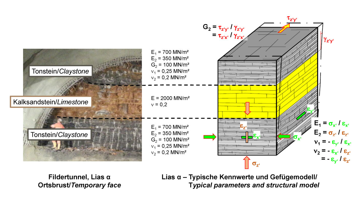 1 | Lias α – Photo of temporary face, structural model and elastic constants as part of the rock mechanical model
Credit/Quelle: WBI GmbH
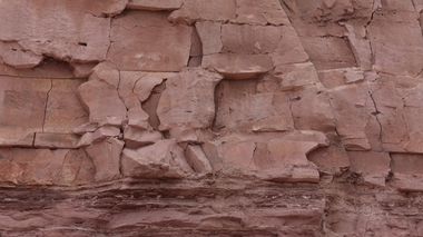
As an example, Figure 1 shows an alternating sequence of sandstones and mudstones from the Lias α of the Lower Jurrasic. The sandstone is characterized by a random grain structure of the intact rock as well as bedding-parallel, horizontal joints and steeply dipping joint sets. Below strength it exhibits an isotropic deformation behavior, which can be described by the deformation modulus E and the Poisson‘s ratio. In contrast, the mudstones have a planar grain structure as well as bedding-parallel, horizontal joints and less pronounced vertical fractures. This leads to an anisotropy of the deformation behavior: the mudstones are more deformable in the vertical direction than in the horizontal, bedding-parallel direction. The by approximation transverse isotropy of the deformation behavior can be described by 5 elastic constants (Fig. 1): the deformation moduli parallel and perpendicular to the bedding E1 and E2, two Poisson‘s ratios ν1 and ν2, and the shear modulus G2 [5, 6].
 2 | Rock mass with 1 set of persistent, filled discontinuities – photo and determination of elastic constants [6]
Credit/Quelle: [6]
Another example of the description of the elastic behavior of jointed rock mass is given in Figure 2, which shows an alternating sequence of sandstones and siltstones of the Waichecheng series. Between the sand- and siltstone layers, bedding-parallel shear zones are present. The shear zones exhibit much higher deformability and lower strength than the surrounding rock packages (sandstone/siltstone). This leads to a transversely isotropic deformation behavior of the rock mass. The elastic constants required to describe this behavior can be calculated comparatively easily from the elastic constants of the individual components (rockmass/shear zone fill). This is schematically shown in Figure 2 on the right. The details together with the formulas are explained in [6].
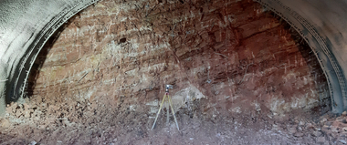
Only in exceptional cases, the strength of the unfractured intact rock is of importance for the mechanical behavior of the rock mass. As a rule, however, results of uniaxial compression tests are available and can be used for the description of the intact rock strength. Assuming an angle of friction for the intact rock φIR, the cohesion cIR can be determined with the Mohr-Coulomb law, as shown in Figure 3 for the example of a Bunter formation.
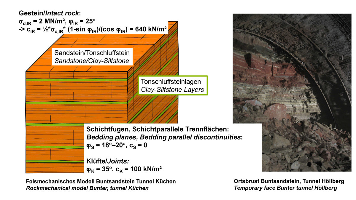 3 | Bunter – photo of temporary face, structural model and strength characteristics as part of the rock mechanical model
Credit/Quelle: WBI GmbH
However, the decisive factors for stability are the shear strengths along the discontinuities, which for practical purpose can also be described by a friction angle and a cohesion in the rock mechanical model, even if nonlinear approaches are available to describe the strength and shear stress-shear displacement behavior. As the example of the Bunter formation in Figure 3 shows, the shear strength along disontinuities is considerably reduced compared to the intact rock strength. This is especially true for the bedding-parallel joints. This leads to an anisotropy in the strength of the rock mass.
A tensile strength is usually not considered in jointed rock. Further examples of appropriate rock mechanical models of jointed rock masses can be found in [6]. These can be used as a basis for initial investigations if results of project-specific explorations are not yet available.
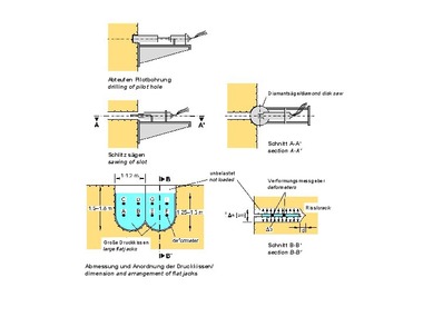
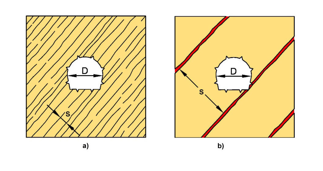 4 | Spacing of discontinuities in comparison with dimensions of engineering structure
a) consideration in homogenous model vs. b) discrete modelling [6]
Credit/Quelle: [6]
When modeling rock mass in the so-called homogeneous model, it is assumed that the discontinuity planes to be considered occur at every point of the model („smeared modeling“). This allows the consideration of various sets of discontinuities, and thus of the anisotropy in strength and deformability, with comparatively little effort. This approach leads to reliable results, if the dimensions of the engineering structure considered are large compared to the discontinuity spacing (s < ~ 1/8 to 1/10 *D, see Fig. 4, left [6]). This condition is usually met for joints, bedding planes, schistosity in sedimentary and metamorphic rocks, and engineering structures of common dimensions. Discrete modeling becomes necessary when the discontinuity spacing is large compared to the dimensions of the engineering structure (see Fig. 4, right). This may be the case for fault zones, for example. If required, it is therefore possible to combine the homogeneous model with discrete modeling of individual structures, such as fault zones [6].
The need for discrete consideration of individual layers or discontinuities must be investigated for each project, both in terms of elastic behavior and strength properties.
3 Case Histories
3.1 Mudstones of the Lower Jurassic
(Lias α), Tunnel Österfeld
A large number of tunnels have been and are still being built in the mudstones of the Lower Jurassic in Germany. For each of the projects, in which the authors have been involved during the last more than 40 years, the results of the explorations carried out were evaluated, and the measurement results obtained during construction were compared with the predictions. Thus, an extensive database is available, which makes it possible to describe the behavior of the rock mass with a very high degree of prediction reliability. This also becomes evident during the current construction of the tunnels for the connection of Stuttgart Airport to the new railway line from Stuttgart to Ulm and of the underground airport station. This will separately be reported in detail. For the purpose of this paper, reference is made to a road tunnel that was successfully designed and constructed using the AJRM method about 25 years ago and is still in operation today. A number of years after completion, a design concept based on classification methods was elaborated for this tunnel for the purpose of comparison with other methods [2].
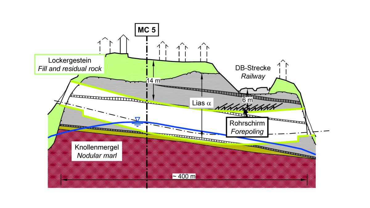 5 | Local by-pass Vaihingen (Stuttgart), Tunnel Österfeld, geological longitudinal section [7]
Credit/Quelle: WBI GmbH
The approximately 400 m long Österfeld road tunnel was excavated as part of the bypass of Vaihingen in Stuttgart (Fig. 5). It is almost entirely located in the Lias α mudstones, whose rock mechanical model is shown in Figure 1. As mentioned above, the mudstones show a pronounced anisotropy of deformability (E1 ~ 2 * E2, Fig. 1). When the design was elaborated, it was known from other projects in the vicinity that increased horizontal stresses were to be expected in the Lias α mudstones in the project area, resulting from pre-loading in geological times. In-situ stress measurements had indicated additional horizontal stresses in the order of ΔσH = 0.2–1.9 MPa. The stability calculations were carried out on the basis of a rock mechanical model taking into account the anisotropy of deformability as well as the increased horizontal stresses using the FE method (AJRM, cf. rock mechanical model in Fig. 1). Based on this, excavation and support as well as the lining of the tunnel were planned. The tunnel was excavated in a mouth profile with a clear width of 11.2 m and a clear height of 9.7 m (Fig. 6, left). For construction reasons, excavation was planned with an advancing vault, which was designed with a closed invert to minimize subsidence. Alternatively, a full face excavation with staggered face would have been possible [8]. The excavation cross-section was secured with a 25–30 cm thick shotcrete membrane and radial anchoring (Fig. 6, left).
 6 | Tunnel Österfeld, excavation and support based on AJRM in comparison with support recommendations according to classification systems Q, RMR and RMi [2, 3]
Credit/Quelle: [3]
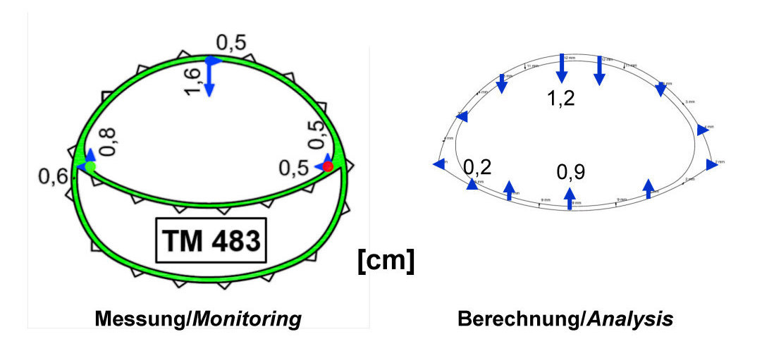
The tunnel excavation was accompanied by a comprehensive measurement program. The measurement results were compared with the computed predictions. Figure 7 shows the comparison of measured and calculated results for the assumption ΔσH = 1 MPa. A very good agreement is noted.
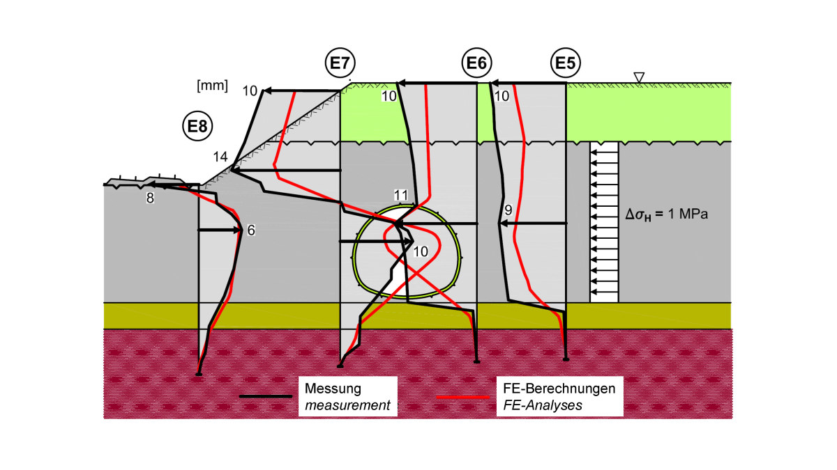 7 | Tunnel Österfeld, horizontal displacement, comparison of analysis and monitoring results [7]
Credit/Quelle: WBI GmbH
This example shows that with a realistic simulation of the strength and deformation behavior of the rock mass according to the AJRM, an economical and safe design was possible already many years ago.
In [2, 3], the Österfeld Tunnel was used as a case study for a comparison with some of the classification systems. The support recommendations determined according to the Q-system, RMR-system and RMi-system assuming the mentioned additional horizontal stress ΔσH = 1 MPa are also shown in Figure 6. For each system, a different support recommendation results. Comparative calculations using the FEM also show that the tunnel would not have been sufficiently stable with the support recommendations determined according to the above mentioned classification systems [2, 3]. Other case studies show that the application of the mentioned classification systems would have resulted in significantly uneconomical designs compared to the AJRM method (cf. [2, 3])
3.2 Bunter Formation, Tunnel Küchen
The tunnel Küchen was built in the course of the Federal motorway A 44 from Kassel to Eisenach [9]. It is located in the Volpriehausen alternating sequence of the Middle Bunter formation, which is intensely bedded and vertically fractured in the area of the tunnel. Fault zones are frequently encountered in the Bunter formation, the location of which cannot always be precisely determined in preliminary investigations. Also in the case of the tunnel Küchen, which was designed with an advanced vault heading with open invert, a fault zone was encountered, which was crossing the tunnel at an acute angle and steeply dipping towards the tunnel [10].
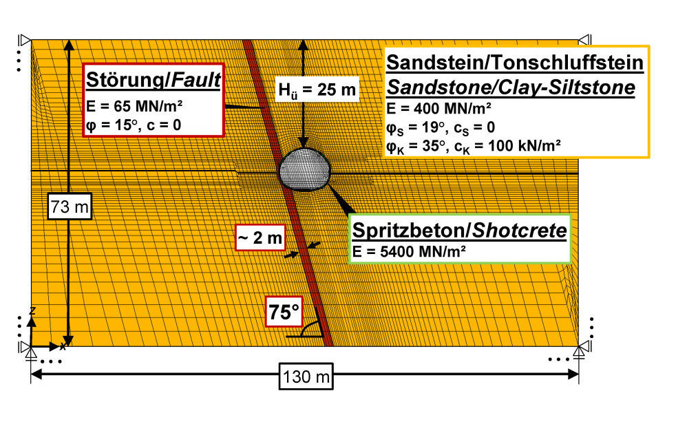 8 | Motorway A44, Tunnel Küchen, fault zone crossing tunnel at acute angle, FE mesh for stability analyses [10]
Credit/Quelle: WBI GmbH
FE calculations were used to investigate the influence of the fault zone on the stability of the tunnel for a vault heading with open invert and with temporary invert. Figure 8 shows the FE mesh used and the characteristic parameters. The fault zone was discretely modeled. For the remaining area of the Bunter, the application of the homogeneous model was sufficient due to the small discontinuity spacing. The strength and deformation behavior of the sandstones and clay-/siltstones of the Bunter formation was described according to the AJRM using the rock mechanical model shown in Figure 3. The fault zone was discretely modeled, as mentioned. Its characteristic parameters were determined from post-calculations (comparison calculation – measurement, see [10]).
 9 | Tunnel Küchen, vault heading with temporary invert, fault zone located beyond zone of influence, comparison of analysis and monitoring results
Credit/Quelle: WBI GmbH
Figure 9 shows the comparison of measurement and calculation results for a vault heading with temporary vault invert (cf. Fig. 10a). In the case shown in Figure 9, the fault zone has a distance of several meters from the tunnel. It can be seen that the displacements in the cross section are not affected by the fault zone and that the results of the measurements and calculations agree to a good approximation.
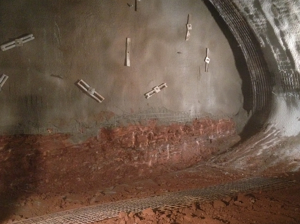 10a | Tunnel Küchen, photo of temporary face with temporary vault invert
Credit/Quelle: WBI GmbH
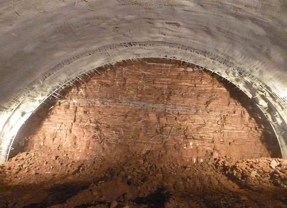 10b | Tunnel Trimberg, photo of temporary face in the Bunter [10]
Credit/Quelle: WBI GmbH
However, when the fault zones comes close to or intersects the tunnel, the displacements considerably increase, especially on the side of the fault zone. The displacements can be controlled with a vault heading with temporary invert (Fig. 11, right), whereas with an open invert, stability cannot be guaranteed in the sidewall area affected by the fault zone (Fig. 11, left). This was also confirmed by on-site observations.
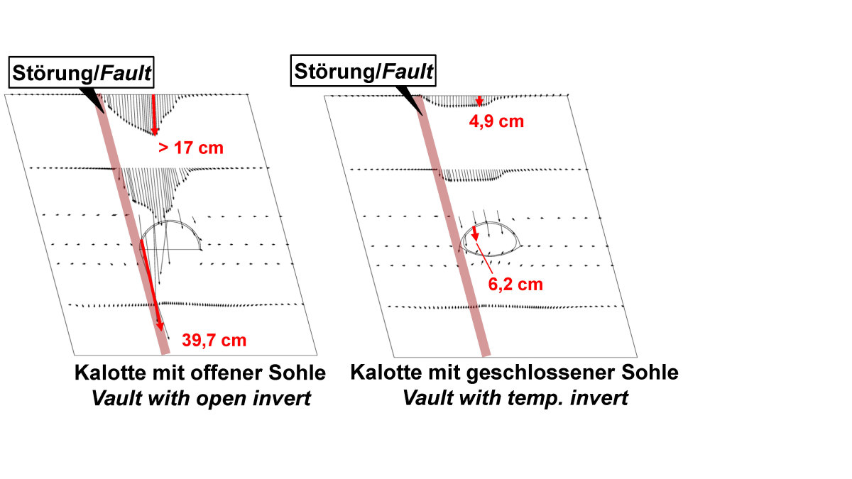 11 | Tunnel Küchen, fault zone located within cross-section of tunnel, displacements for a vault heading with open invert and with temporary invert [10]
Credit/Quelle: [10]
This example shows very clearly that it is essential for a safe design to understand and realistically take into account the anisotropy of the strength and deformability resulting, for example, from alternating sequences, discontinuities and also fault zones. It also becomes clear that this is possible with the AJRM. The effort for corresponding calculations is nowadays no longer to be seen as an obstacle for the application.
 12 | New high-speed railway line Hannover–Würzburg, cut Körle, rock slope in the Bunter
Credit/Quelle: WBI GmbH
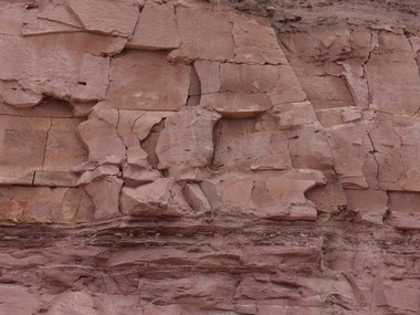
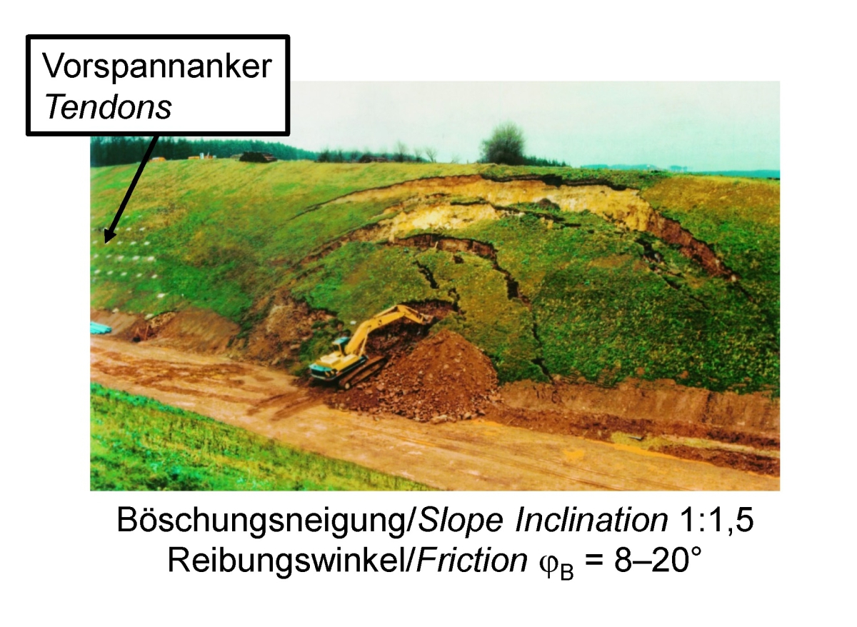
Another example from the Bunter formation is shown in Figure 12. Although it dates back several years, it is still relevant for structures built in the Bunter in recent times and those to be built in the near future. Numerous cuts were constructed in the Bunter formation for the new railway line between Kassel and Fulda. Due to the small shear strength on the bedding-parallel joints of the Bunter (friction angle φB ~ 8–20°, cB ~ 0) and due to their dip angle, the embankments had to be extensively secured with prestressed anchors, though a shallow inclination of only 30° was foreseen. Without this anchoring, failure occurred along the bedding-parallel discontinuities (Fig. 12). However, such effect can only be accurately recognized, if the strength anisotropy of the Bunter formation is accordingly taken into account.
 13 | Green Line, Qatar, Simsima Limestone, Rock mass parameters based on Hoek-Brown [11] in comparison with AJRM [13, 14]
Credit/Quelle: Bild oben links -> [11]. Rest: WBI GmbH
 14 | Green Line, Qatar, Midra Shale, Rock mass parameters based on Hoek-Brown [11] in comparison with AJRM [13, 14]
Credit/Quelle: [11]; WBI GmbH
3.3 Limestone, Green Line, Qatar
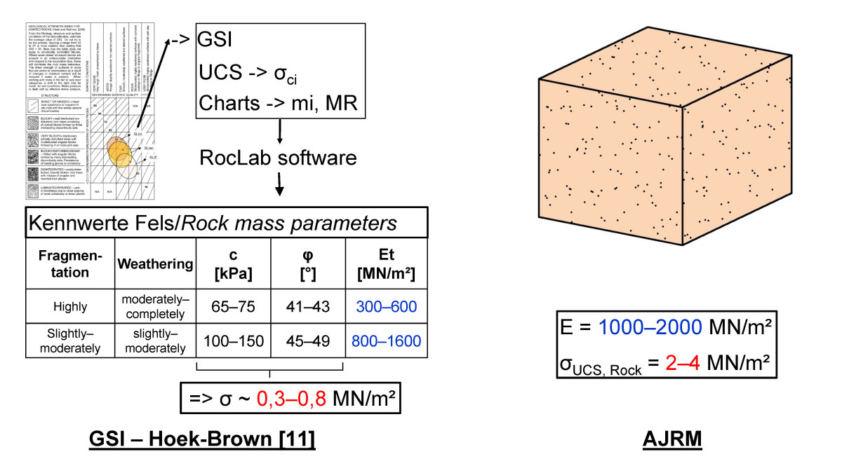
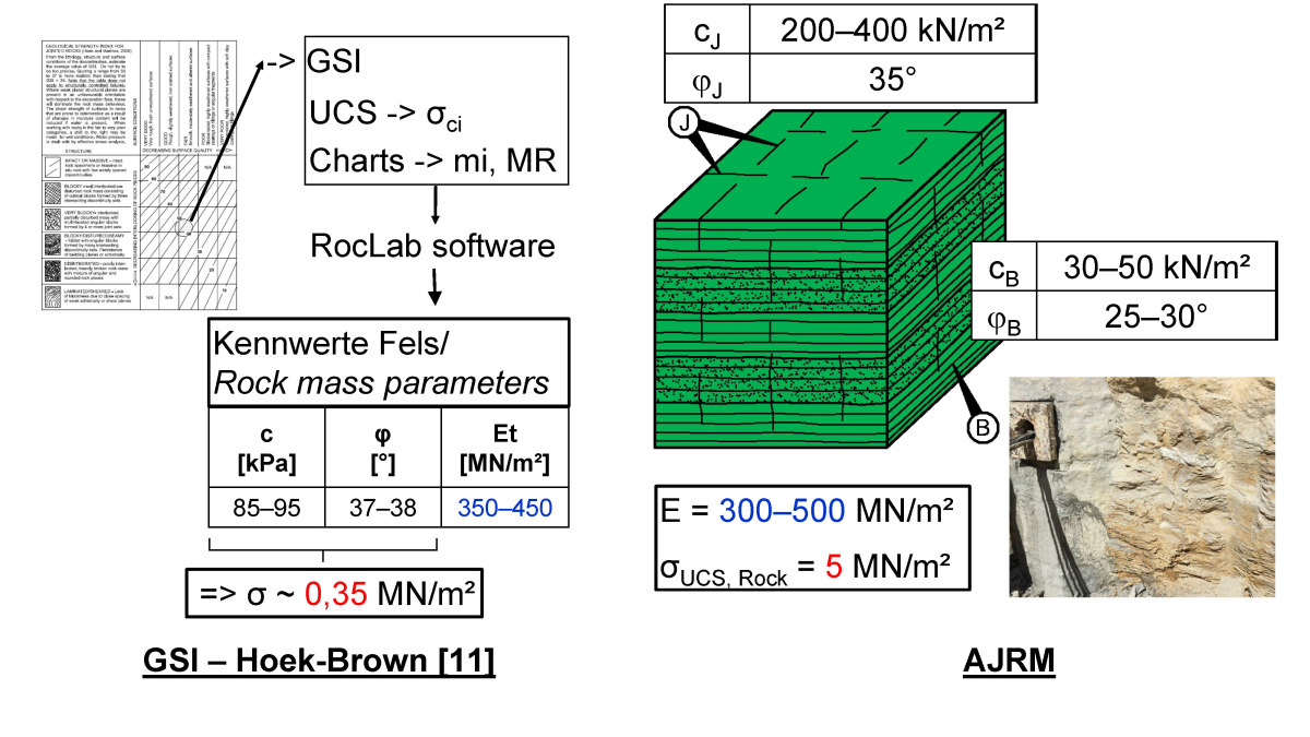
For the future stations of the Green Line of the metro Qatar, numerous construction pits were constructed in Tertiary limestone. The designer determined the characteristic values of the rock mass on the basis of the Hoek-Brown failure criterion [11]. Based on the exploration results and his own estimation, and with the help of Hoek-Brown‘s graphs, the designer determined the GSI values, the intact rock strengths (σci), the constant mi and the ratio value MR. On this basis, he used RocLab software [12] to determine the characteristic values of the rock mass, cohesion, friction angle, and deformation modulus. As an example, the results for two important geological units, the Simsima Limestone and the Midra Shale, are shown on the left hand side of Figures 13 and 14, respectively. The rock mass is considered like a homogeneous, isotropic material. Comparatively small isotropic strengths are given,
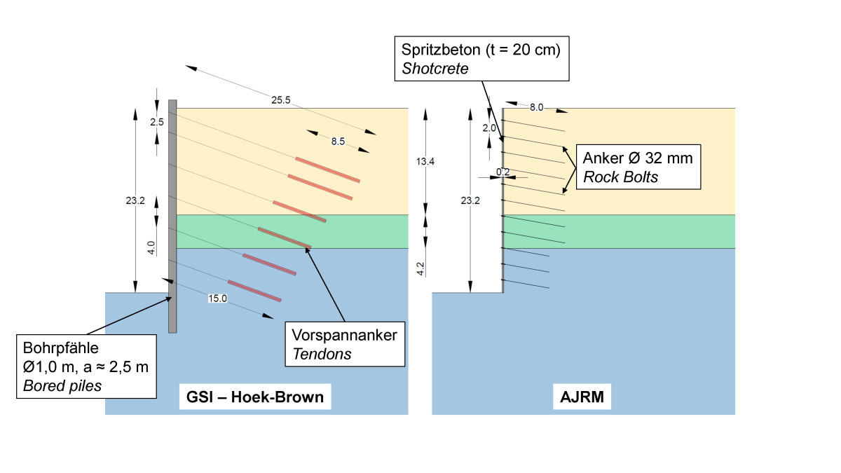
which, especially in the case of the Midra Shale, are of the order of the shear strength of the approximately horizontal, bedding-parallel discontinuities. On this basis and applying the relevant loads, the excavation support was designed. Because of the small strengths assumed, a heavy support with a discontinuous bored pile wall was required. The bored piles, which had a diameter of 1 m, were tied back every 2.5 m to 4 m with 15 to 25.5 m long prestressed anchors (see Fig. 15, left).
 15 | Green Line, Qatar, Support of construction pit dimensioned with parameters according to Hoek-Brown [11] in comparison with AJRM [10]
Credit/Quelle: [10]
At the request of the contractor, the authors elaborated their own design using the AJRM approach. A site visit and the study of the exploration results revealed that the Simsima Limestone, which is encountered along the upper two-thirds of the excavation pit (Fig. 15), is a fine-grained crystalline limestone with almost no fractures nor bedding-parallel discontinuities. It is homogeneous and isotropic with respect to strength and deformability. The rock mechanical properties were estimated as shown in Figure 13, right. In particular, the strength is significantly higher than the value determined by the designer according to Hoek-Brown (Fig. 13, left).
The Midra Shale, which underlies the Simsima Limestone, exhibits a pronounced horizontal bedding with small spacing (photo in Fig. 14). In addition, steeply dipping joints are observed. This results in an anisotropy of strength, which is considered according to the AJRM, by means of taking into account the intact rock strength on one hand side, and the reduced shear strengths along the discontinuities, on the other hand side (see Fig. 14, right). An isotropic deformability in the elastic range was assumed. The deformation modulus was assumed in the same order of magnitude in both approaches. However, the comparison of the strength parameters according to AJRM with the strength parameters determined with the designer‘s approaches based on Hoek-Brown, shows significant differences. As already mentioned, in the approach according to Hoek-Brown, the rock mass was considered homogeneously isotropic. The designer defined strength values for the rock mass, which are in the order of magnitude of the shear strength along the bedding-parallel discontinuities. Thus, the rock mass was more or less simulated like a soil. This does not adequately take into account the real conditions and, especially for the horizontal orientation of bedding encountered here, leads to a clear overdimensioning of the support measures.
For the lowest geological unit, which will not be considered in detail here, the result of comparison is similar to that for the Midra Shale.
With the characteristic parameters determined according to AJRM on the basis of the explorations and the experience of the authors, and under consideration of the same load assumptions, it was possible to prove the stability of the excavation with a significantly less extensive support consisting of 20 cm shotcrete and up to 8 m long SN anchors arranged in a grid of 2 m x 3 m (Fig. 15, right). The realistic consideration of the strength and deformation properties of the rock mass thus allowed for a considerably more economical design and construction in this case. Unfortunately, the optimized design could only be partially implemented on site, since a large portion of the bored piles had already been executed.
4 Outlook on Part 2
The presentation of the case studies shows very clearly that the realistic simulation of the deformability and strength of the rock mass with the AJRM enables a safe and economical design. This can also be confirmed by measurements during construction.
In part 2 of the article, the rock hydraulic model belonging to the AJRM is presented along with selected case studies. In addition, the methods for determining the rock mechanical and rock hydraulic characteristic parameters are discussed.