Design and Construction of Tunnels in Jointed Rock According to the AJRM Method – Part 2
The first part of this article was published in the 3/2021 issue of tunnel [15]. There, the authors present the AJRM method. The rock mechanical model is explained. With the aid of case studies, the advantages of a realistic simulation of the behavior of jointed rock as well as of the interaction of rock mass and structure are illustrated. As announced, part 2 of the article deals with the rock hydraulic model and related case studies as well as with the determination of the required parameters. Thus, an overall method for a safe and economic design of structures as well as for groundwater modeling in jointed rock is available.
4 Determination of Rock Mechanical Properties
4.1 Laboratory and Field Tests
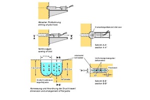
The discontinuities have a decisive influence on both, the deformability and the strength of a rock mass. Therefore, in order to obtain reliable information on the deformability of the rock mass, strictly speaking, it is necessary to test rock volumes whose size is a multiple of the discontinuity spacing. Since samples with such dimensions can hardly be taken and transported to a laboratory, field tests were developed in the early days of rock mechanics, which enable testing large volumes of rock mass. In Large Flat Jack (LFJ) tests, for example, flat jacks ranging in size from one to several square meters are inserted into sawn slots, and slot openings are measured as a function of applied compressive stress (Fig. 16 [5, 6]).
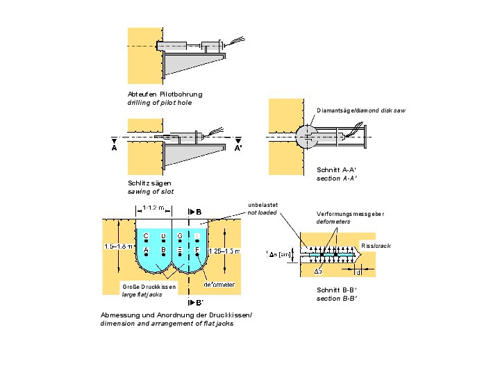 16 | Large Flat Jack Test
Credit/Quelle: [6]
From the measurement results, the deformation modulus of the rock mass can be derived. For cost reasons, these tests are not carried out as often. Instead, borehole expansion tests such as dilatometer or pressiometer tests are often carried out in exploratory drillings. In these tests, only a small rock mass volume is investigated. As a consequence, the influence of the discontinuities on the deformability is usually not recorded in a representative manner. As a result, these tests usually yield deformation moduli that are too high. This must be taken into account when evaluating the test results and deriving the rock mass parameters.
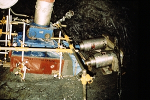
Also for determining reliable values for the shear strength along discontinuities, large-scale tests are needed. In-situ direct shear tests can be considered for this purpose (Fig. 17 [5, 6]). The strength of the intact rock, however, can be determined in laboratory tests on drill cores.
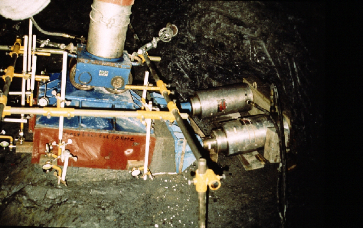 17 | In situ shear test
Credit/Quelle: Interfels GmbH
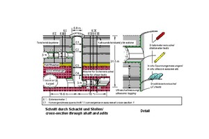
In the case of large scale construction projects for traffic tunnels or hydraulic structures, it is advisable to carry out rock mechanics testing programs in connection with advanced construction measures, such as access tunnels, ventilation shafts or similar. Figure 18 [5, 6, 10] shows a relevant example in which a ventilation shaft and two exploratory galleries were excavated before the start of the main construction work.
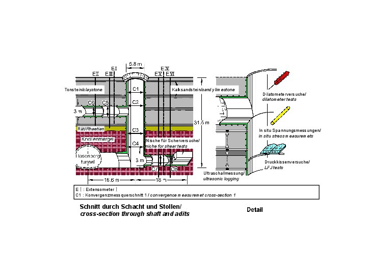 18 | Rock mechanical investigation program
Credit/Quelle: [5, 6, 10]
Here, LFJ tests, in-situ direct shear tests, dilatometer tests, ultrasonic measurements and primary stress measurements were carried out. In addition, excavation-induced displacements were measured using extensometers and convergency measurements. Based on the results of the rock mechanics tests and an interpretation of the measured displacements using numerical calculations, it was possible to develop a reliable rock mechanics model with the required characteristic parameters.
As mentioned above, the investments associated with the rock mechanics investigations can be combined with advanced construction measures. They usually pay off many times over due to the possibilities of safe and economic design and construction on the basis of reliable and realistic characteristic parameters.
However, in case the experts contributing to a project have the required experience, it is also possible to determine the required parameters on the basis of small-scale tests (cf. chapters 4.2 and 4.3).
4.2 Interpretation of the Results of Measurements During Construction
In modern tunnel construction, the stability analyses do not only include the design of the temporary support and the internal lining, but also a prognosis of the expected displacements. Furthermore, the displacements of the cavity contour and the surrounding rock mass are continuously measured during heading and compared with the above-mentioned prognosis. On this basis, the tunnelling works and, in particular, the supporting measures are adapted to the conditions.
Moreover, the interpretation (calibration) of the measurement results with adequate rock mechanical models and calculation methods allows for deriving reliable rock mechanical characteristic parameters. This makes it possible to compensate for any possible deficits in previous exploration phases (cf. chapter 4.1), if the other conditions of the project (e.g. contractual) enable a flexible adaptation to the encountered rock mass conditions. Also on the basis of such backanalyses, the authors have gained experience in numerous different rock mass conditions and have built up an extensive body of experience.
4.3 Empirical Values
From the above-mentioned body of experience, selected examples are given below.
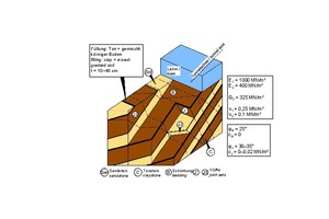
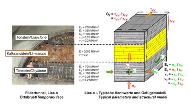
In the course of the design and construction of a road tunnel in Wuppertal [7], the rock mechanics model shown in Figure 19 was developed. It shows an alternating sequence of sandstones and claystones beneath a cover of cohesive soil. The bedding parallel discontinuities exhibit fillings of clay and mixed-grained soil and lead to an anisotropy of deformability that can be described by the 5 elastic constants shown in Fig. 19 (cf. also Fig. 2 in part 1 of this publication [15]).
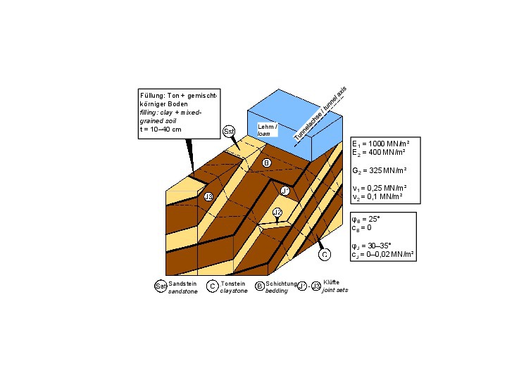 19 | Devonian sedimentary rock mass with clay fillings in bedding parallel discontinuities
Credit/Quelle: [6, 7]
The shear strength along the bedding parallel discontinuities can be described with an angle of friction φB = 25° and a cohesion cB = 0 kN/m². For the shear strength along joints, a cohesion other than 0 can usually be taken into account in addition to the friction angle (Fig. 19).
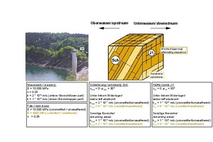
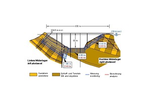
For the alternating sequence of sandstone and claystone, as encountered in the area of the Urft dam in the Eifel mountains, an isotropic stress-strain behavior in the elastic range was found. However, in this case, a distinction had to be made between a near-surface weathered zone and the deeper unweathered part of the rock mass (Fig. 20, [6, 16]).
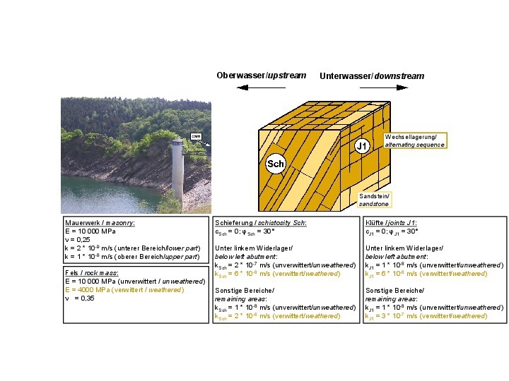 20 | Rock mechanical model for the foundation of the Urft dam
Credit/Quelle: [6, 16]
The shear parameters along schistosity and joints are also compiled in Figure 20. Furthermore, the permeability coefficients in parallel with the schistosity and joints can be found in this figure. It should be noted that the permeability of the left rock abutment is greater than that in the other areas (cf. chapters 5 and 6).
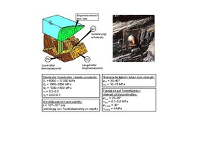
The rock mechanical model of a clay shale from the Ernstbach valley near the town of Rüdesheim at the Rhine river is shown in Figure 21 [17, 6, 5]. It can be noted that the clay shale is strongly anisotropic in terms of both, deformability and strength. This is mainly due to the schistosity.
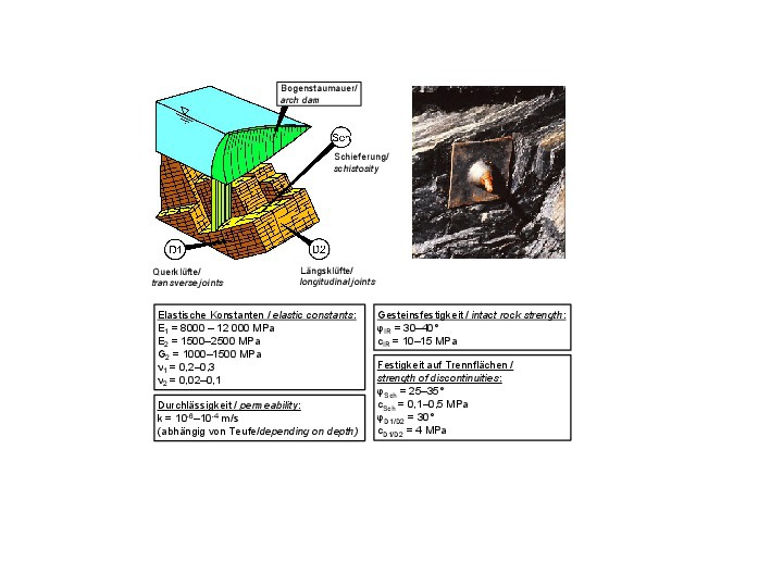 21 | Rock mechanical model for a clay slate
Credit/Quelle: [5, 6, 17]
Further examples of this type can be found in [6]. The characteristic parameters given there for different rock mass conditions can be used as a basis for initial considerations in early project phases, when no other results are yet available, if the project participants have the required experience.
5 Rock Hydraulic Model
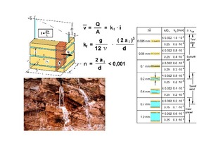
According to experience, the intact rock has a very low permeability and can be assumed to be impermeable, with a few exceptions only. Seepage flow in rock mass generally occurs through the discontinuties (cf. Fig. 22, bottom left) and is usually laminar.
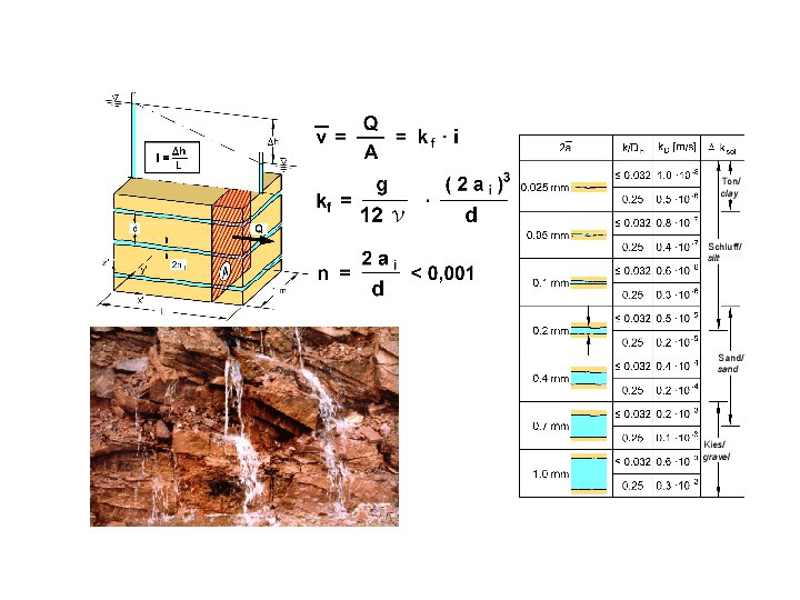 22 | Seepage flow through a set of parallel discontinuities and influence of the opening width of the discontinuities on the permeability of a rock mass
Credit/Quelle: [5, 6]
The average flow velocity for one-dimensional flow in a discontinuity can be derived by integrating the Navier-Stoke‘s differential equations. For the one-dimensional seepage flow through a set of parallel discontinuities with constant spacing and constant opening width, a filter velocity related to the total cross-section is defined, following Darcy‘s law from soil mechanics (cf. [5, 6, 10] and Fig. 22, top left). This filter velocity is proportional to the 3rd power of the discontinuity opening width 2ai and inversely proportional to the discontinuity spacing s¯. Thus, the opening width of the discontinuities 2ai has a major influence on the seepage flow in rock masses, in addition to the discontinuities spacing and the viscosity of water.
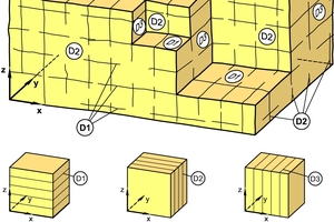
For the three-dimensional case of a rock mass with three sets of discontinuities, which are perpendicular to each other, a permeability matrix can be determined by superposing the permeabilities of the individual sets of discontinuities. This matrix has values deviating from 0 only in the main diagonal, and multiplied by the three components of the spatial gradient I, it yields the three components of the filter velocity (Fig. 23 [5, 6]):
{v} = [K] ∙ {I}
In this approach, the flow losses along the lines of intersection of the discontinuities are neglected. This assumption is permissible for the low flow velocities occurring in practice. A similar approach is taken in the case of discontinuity sets that are not perpendicular to each other [5, 6].
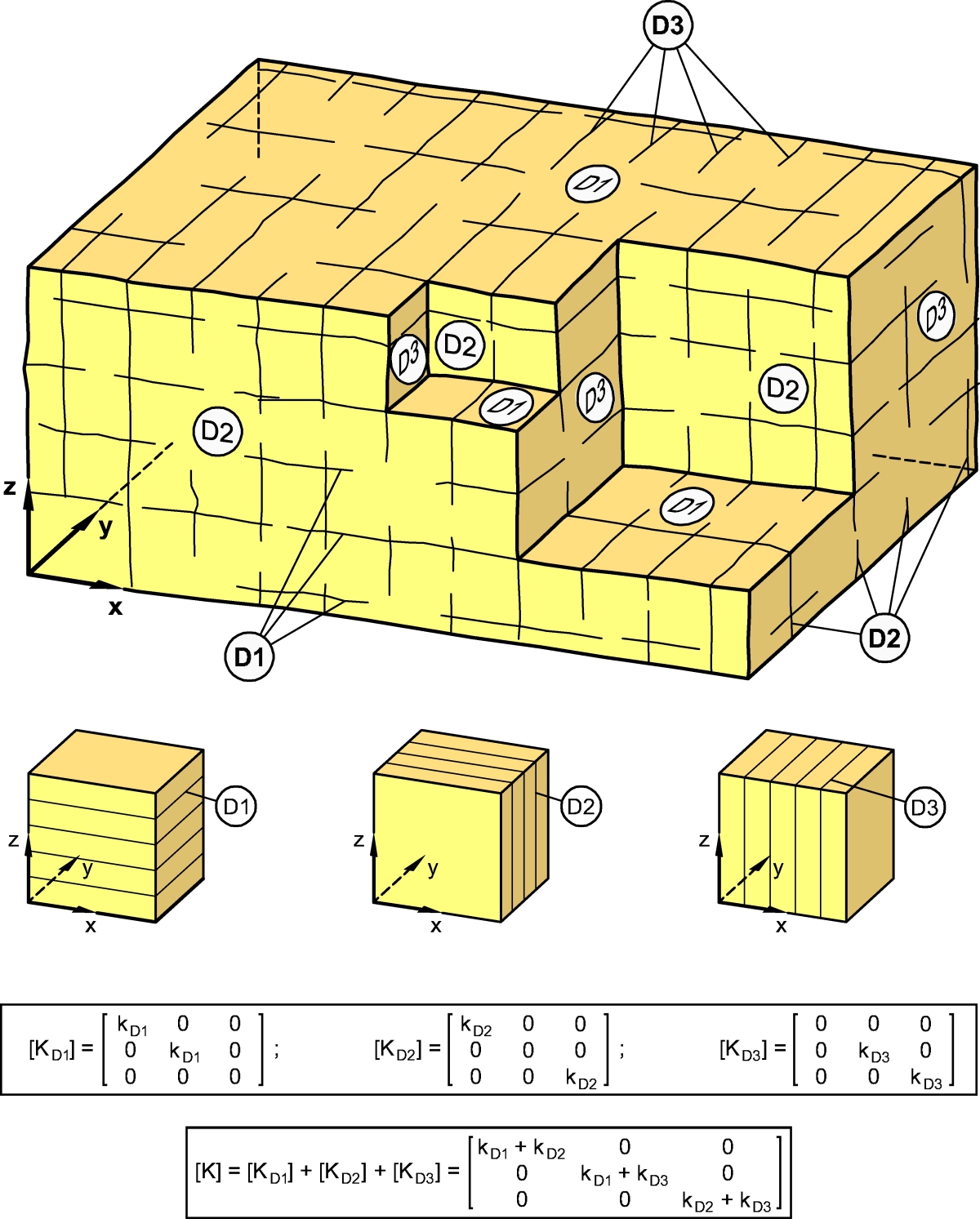 23 | Permeability of a rock mass intersected by three orthogonal sets of discontinuities
Credit/Quelle: [5, 6]
In most cases, the permeability of the rock mass is strongly anisotropic. Only in the special case of three orthogonal discontinuity sets with equal permeability, a rock mass exhibits an isotropic permeability. The anisotropy of permeability strongly affects the direction of the resulting velocity of the seepage flow as well as of the seepage pressure. This makes the study of seepage flow in rock masses quite different from corresponding considerations in coarse-grained soils.
Figure 22 on the right contains a compilation of the permeability coefficients of a rock mass with a set of discontinuities with a constant spacing of 1 m and a constant opening width. It can be noted that the permeability of a rock mass with comparatively small opening widths of the discontinuities of only 0.7 to 1.0 mm already exhibits permeability values of a gravelly sand. On the other hand, the fracture volumes and thus also the storage capacity of the rock mass, are significantly smaller than those of a gravel. Both aspects are very important and have to be taken into account in design. For example, cutting water-filled discontinuities with small opening width during construction can lead to significant water inflows. In addition, the low fracture volume causes the groundwater table to rise much more after precipitation than, for example, in coarse-grained soils. The low fracture volume must also be taken into account when designing water catchment systems.
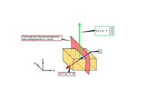
As in soil mechanics, the volume forces transmitted to the rock mass by the seepage flow are divided into the hydrostatic uplift {Fu} and the hydrodynamic seepage pressure {Fs} acting perpendicular to the areas of equal potentials (Fig. 24 [6]).
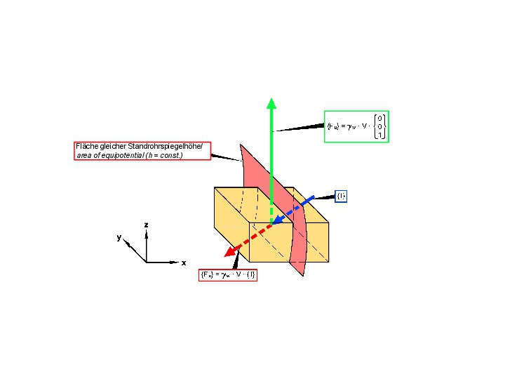 24 | Uplift and seepage pressure in a jointed rock mass
Credit/Quelle: [6]
The seepage pressure can have a considerable influence on the stability of slopes and dam abutments, for example, as well as of the temporary face in tunnel construction. Seepage flow must therefore be taken into account in stability analyses. As already mentioned, it must, however, be borne in mind that the permeability of rock mass is anisotropic such that the potential distribution does not result nor can it be determined in the same simple way as for soil mechanics issues in coarse-grained soils. This must be taken into account accordingly in stability considerations.
6 Case History
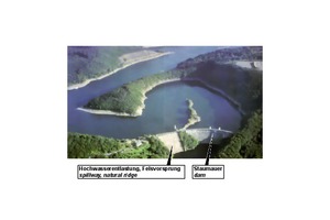
The Urft dam is an approx. 60 m high quarry stone masonry dam, which was designed and built around 120 years ago. It is located in the Eifel region near the city of Aachen (Fig. 25 [16]). According to nowadays criteria [18], the stability of the dam could no longer be verified for all load cases.
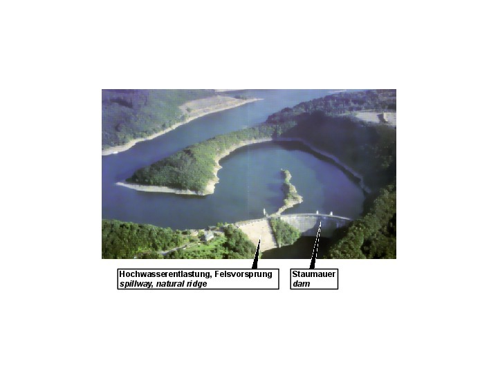 25 | Urft dam and reservoir
Credit/Quelle: [23]
The rehabilitation concept required for this reason, provided for the construction of two drainage and inspection galleries as well as the arrangement of vertical drainage boreholes in the dam [6]. In addition, the arching effect of the double-curved dam was taken into account in the stability analyses, i.e. it was considered that part of the water pressure acting on the dam’s upstream surface is transferred to the rock abutments. This assumption entails that the analyses do not anymore result in tensile stresses at the level of the dam foundation on the upstream side [16]. The approval authority agreed to this solution with the condition that the load-bearing behavior assumed and demonstrated in the 3D FE calculations be confirmed by measurements carried out on the structure after its rehabilitation. This also included the investigation of the seepage flow underneath and aside the dam, which is founded on a clay slate.
The rock mechanical model and characteristic parameters derived from the results of the preliminary investigations and the calibration carried out after the rehabilitation works, are compiled in Fig. 20. The discontinuities, which are decisive for the seepage flow, are the vertical joint set J1, striking from the upstream to the downstream side, and the schistosity Sch, which is striking perpendicularly to the valley and dipping steeply towards the upstream side. For both discontinuity sets, a distinction must be made between a weathered zone near the ground surface and an underlying unweathered zone. The permeability coefficients are in the order of magnitude of 10-6 to 10-8 m/s. The schistosity has a higher permeability than the joints, or in some cases the permeabilities are the same, respectively.
In view of the low permeabilities, a grout curtain was not considered to be necessary. Nor were drainage drillings in the bedrock required, since the schistosity dipping towards the upstream side acted as a drainage due to its permeability.
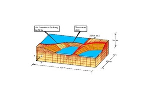
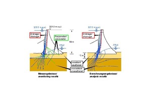
The 3D FE analyses determining the seepage flow underneath and aside the dam (Fig. 26) resulted in the potential distributions shown in Figure 27, which were confirmed by the results of the piezometric measurements in the bedrock and the dam.
Also, the seepage flow rates measured in the lower control gallery are in good agreement with the calculated results (Fig. 28).
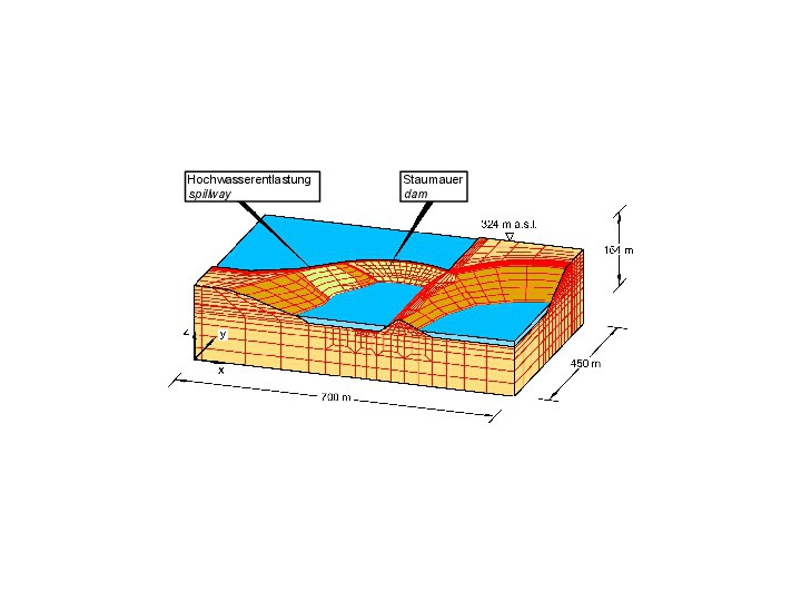 26 | FE mesh for investigation of seepage flow through dam and foundation
Credit/Quelle: [6, 16]
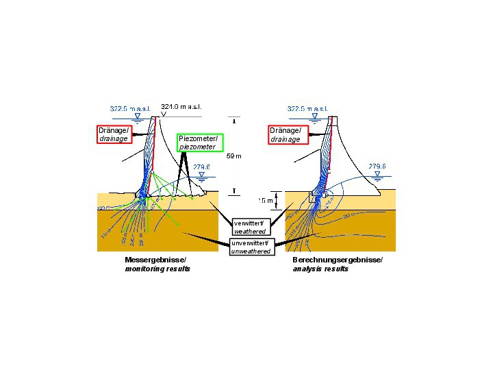 27 | Seepage flow through dam and foundation, comparison of analyses and monitoring results
Credit/Quelle: [6, 16]
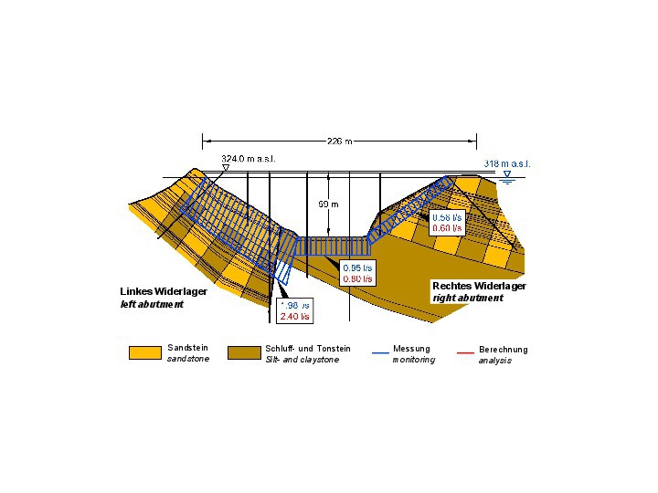 28 | Seepage losses, comparison of analyses and monitoring results
Credit/Quelle: [6, 16]
7 Determination of the Rock Hydraulic Parameters
The characteristic parameters required for the application of the rock hydraulic model described in the preceeding chapters can be determined using the generally accepted and used investigation methods. Therefore, these are only briefly touched upon below.
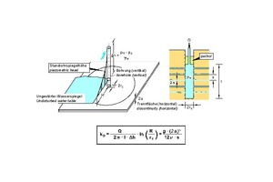
In a standard packer test (Lugeon test), water is injected under pressure from a defined borehole section, which is sealed at the top by a packer, into the surrounding rock mass. The permeability coefficient of the rock mass is then determined from the amount of water absorbed and the pressure applied (Fig. 29 [6]). In order to determine the permeability of the discontinuity sets and thus the components of the permeability matrix, it is advisable to arrange the boreholes at least approximately perpendicular to the respective discontinuity sets.
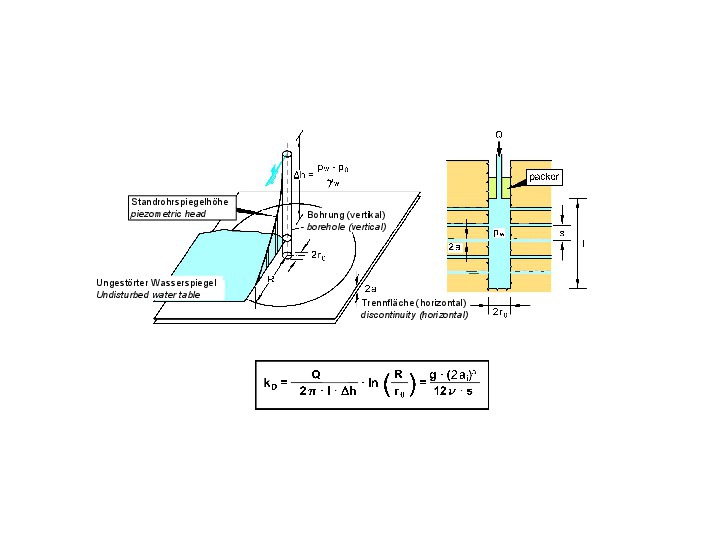 29 | Evaluation of a standard packer test
Credit/Quelle: [5, 6]
Constant or falling head tests are also suitable for determining the permeability of a rock mass [19, 6].
While in the above tests the area investigated is limited to the immediate vicinity of the borehole in question, pumping tests – when combined with piezometer measurements in the vicinity of the pressurized borehole – can be used to determine the permeabilities of larger areas of a rock mass [20]. For rock masses with low permeability coefficients, pulse tests and also air permeability tests are suitable [6, 21].
A test equipment that can measure permeability coefficients down to 10-10 m/s using acrylic gel or even water as test fluid, has been developed and used by WBI GmbH [22].
8 Summary and Conclusions
For a safe and economic design of structures in a jointed rock mass, a realistic consideration of the interaction between rock mass and structure is required. This requirement is neither fulfilled by the subgrade reaction method nor by classification systems (Q, RMR, RMi). Also the procedure on the basis of the GSI and the Hoek-Brown failure criterion, introduced by Hoek-Brown, in many cases is not adequate, since it assumes isotropic rock mass behavior.
The given two-part paper (part 1 in [15]), however, presents a model for anisotropic jointed rock mass that has been used by the authors for many years in the design and construction of structures in rock mass with great success. With a realistic description of the mechanical and hydraulic behavior of jointed rock under consideration of anisotropy, it is possible to find safe and economic solutions.
In the two-part article, both the mechanical and the hydraulic model are explained. The determination of the required characteristic parameters is discussed, and some case studies are presented. This way, the fundamentals and selected case studies are explained, on one hand side for the statical consideration, dimensioning and design of structures in rock mass and, on the other hand, for hydrogeological considerations (groundwater models), always bearing in mind that the forces resulting from seepage flow must, of course, also be taken into account in the statical proof.
The authors would like to explicitly encourage technical discussion and hope that further research work on refining the AJRM method will be done. Already now, a broad application of the presented approach would lead to more cost-effective and safer solutions than are possible with conventional design methods.

