Digitalised Condition Recording of the Inner Lining of the Auberg Tunnel
 Credit/Quelle: Marti GmbH Deutschland
 Credit/Quelle: Marti GmbH Deutschland
 Credit/Quelle: Marti GmbH Deutschland
 Credit/Quelle: Marti GmbH Deutschland
 Credit/Quelle: Marti GmbH Deutschland
 Credit/Quelle: Marti GmbH Deutschland
 Credit/Quelle: Marti GmbH Deutschland
 Credit/Quelle: Marti GmbH Deutschland
 Credit/Quelle: Marti GmbH Deutschland
In a pilot project, the company Marti GmbH Deutschland investigated which BIM-based applications should be implemented in conventional tunnelling, and the process of recording the condition of the inner lining was selected. Using the of the new Auberg Tunnel project in Germany, model-based recording of the condition
of the inner lining is compared with the analog procedure and the relevant exampleadvantages and disadvantages are derived.
1 Introduction
Digitalisation is also becoming ever more significant in tunnelling. The reform commission “Construction of major projects”, set up in 2013 by the German Federal Ministry of Transport and Digital Infrastructure [1], produced various recommendations for action for the remediation of structural deficits. One application example was the use of Building Information Modelling (BIM) to optimise project implementation. The subsequent stage plan “Digital Design and Building” [2] stated that the BIM method should be used regularly on infrastructure projects to be designed from the end of 2020.
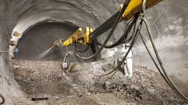
The company Marti GmbH Deutschland investigated various BIM application cases in order to gain further experience with the implementation of BIM in the construction phase of the Auberg Tunnel. In addition to model-based controlling of construction progress and quantity measurement, recording of the condition of the concrete inner lining using a BIM model and a robust site tablet were also tested during the construction phase (Fig. 1).
2 Project Description
The Auberg Tunnel is a 440 m long single-tube road tunnel with two-way traffic, which is being excavated by conventional methods starting in April 2018 with a common 100 m2 profile. It should be structurally complete by April 2020. The tunnel is the central structure of the bypass of the town Altenmarkt an der Alz. The tunnel passes under the unbuilt and wooded Auberg (Fig. 2) with a maximum overburden of about 37 m.
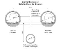
The main tunnel is being constructed as a two-pass construction with all-round waterproofing between the inner and outer lining. Due to the geological conditions and for operational reasons, a continuous arch section with invert arch is planned along a length of 400 m. In order to fulfil the safety requirements for road tunnels, an escape and rescue tunnel was driven with a length of 133 m leading directly to the open air. In the escape and rescue tunnel, a 15 cm thick shotcrete inner lining was installed.
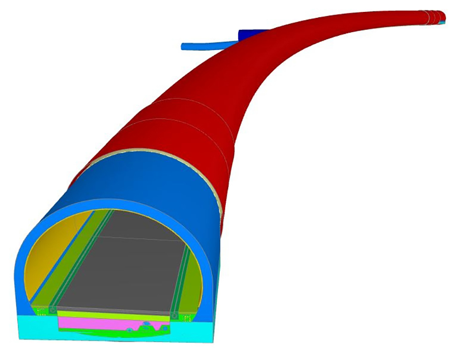
Fig. 3 shows the necessary digital structure model for the application case of the Auberg Tunnel. The structural and detail depth of the model are based on the individual application cases. In the stated application case, a low degree of detailing is adequate for the model geometry. It is essential to assign and store central and structured project information.
3 Condition Recording of the Inner Lining
3.1 General
In conventional tunnelling, is it usual to differentiate the temporary support provided by a shotcrete layer and the final support provided by an inner lining, with a lifetime of up to 100 years being set for the final lining, during which time structural stability and serviceability have to be ensured. However, defects can arise in the process of constructing the inner lining, leading to high repair costs and possibly severe restrictions of serviceability during the course of the lifecycle. In order to counter laborious and expensive repair measures under continued operation, such defects have to be remedied during the construction phase.
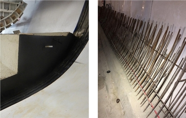
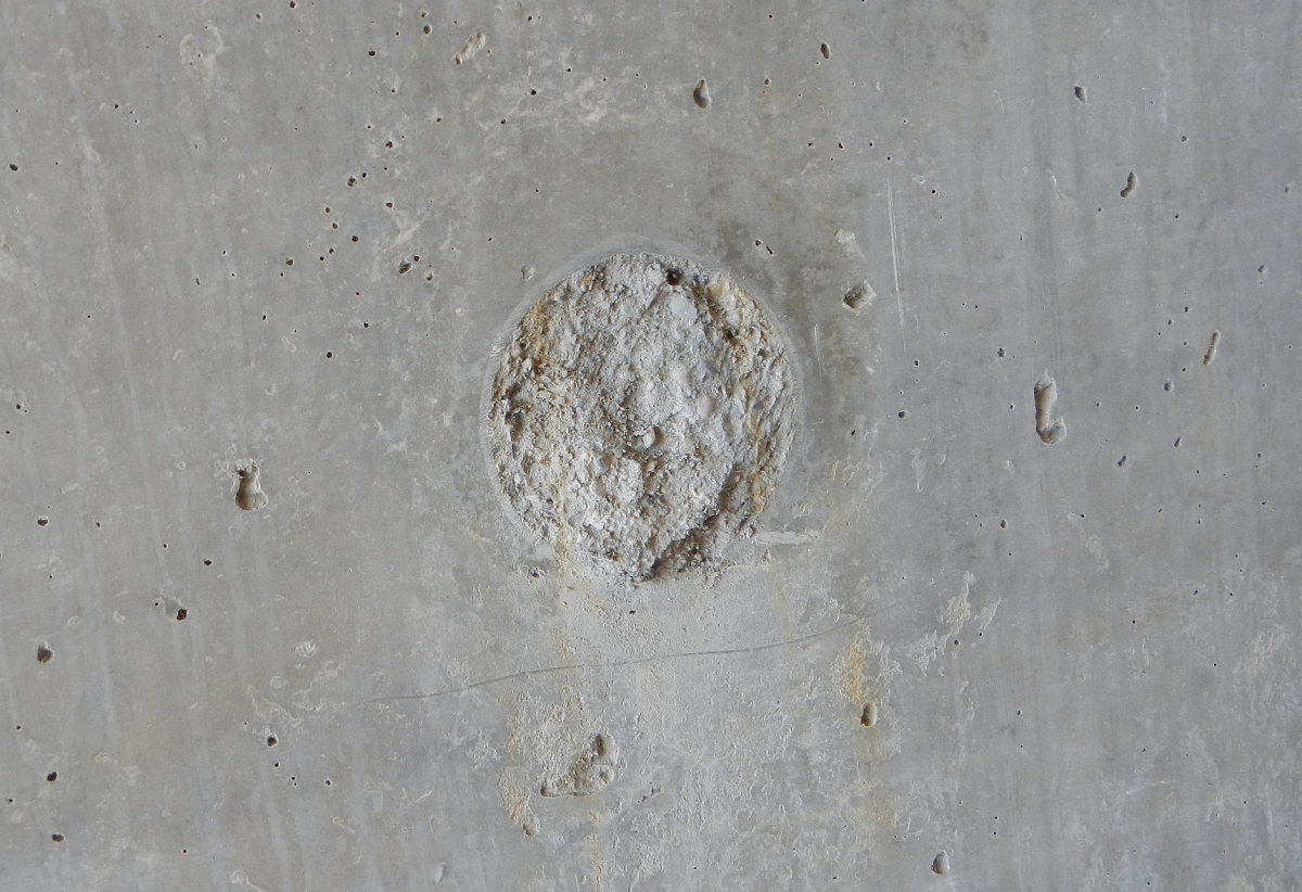
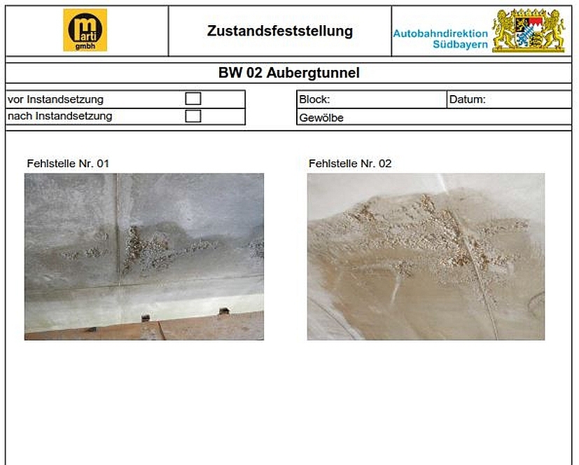
Fig. 4 shows an example of a possible defect, which can arise through defective construction. The illustrated defect can be caused by the improper setting of the filling connection of the mobile formwork unit (further possible defects to the inner lining are shown in [5]).
In a project-specific repair plan, the contractor has to describe any possible defects, which can occur in the course of concreting. Based on this, defect-specific repair measures are then to be described based on current guidelines for the remediation of defects. A further part of the plan is a description of a procedure to survey the condition before and after defect remediation. Below, the procedures for conventional and model-based condition recording are described and the advantages and disadvantages are compared.
3.2 Conventional Condition Recording
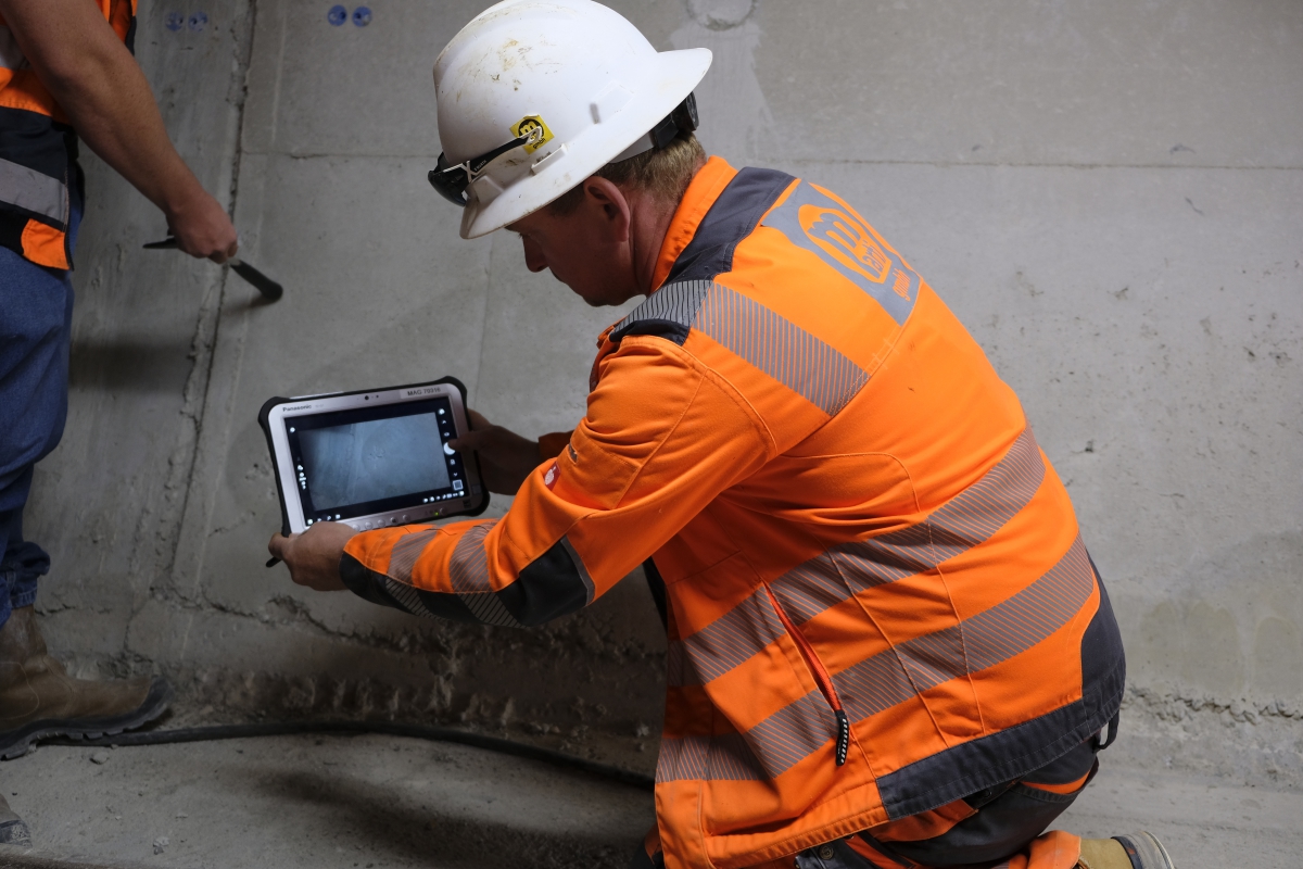
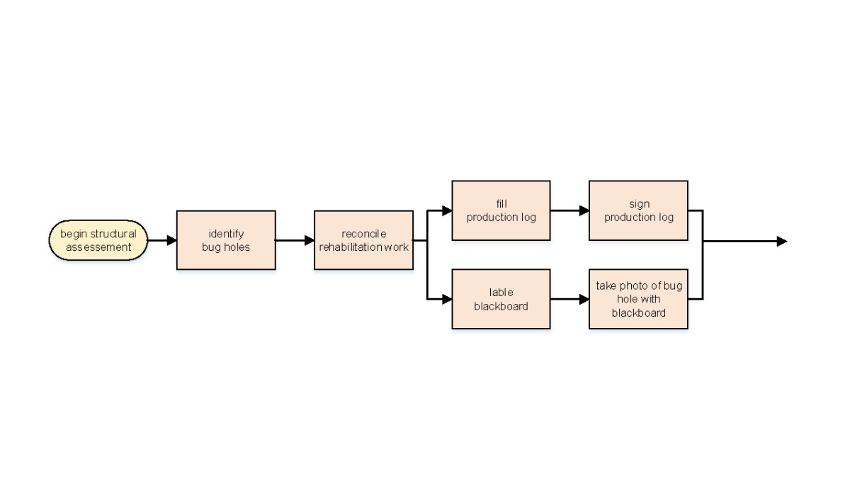
Recording of condition, an essential part of the repair plan, involves a lot of time for conventional documentation. This is split into recording on site in the tunnel (Fig. 5) and processing in the site office (Fig. 6).
The first step of recording on site is the identification of possible defects in collaboration between the contractor and the site supervision and an agreement regarding the implementation of necessary repair works. The defect is categorised and recorded on site in a paper-based protocol including the agreed repair measures. The individual defects are also photographed with a digital camera. In order to ensure correct assignment, a small panel with information is newly written for each defect and held in the picture. Then the collaboratively produced protocol is signed on site by the contractor and the site supervision.
After recording in the tunnel, the documents are processed by the contractor in the site office, with the paper-based and signed protocols being scanned and provided with an adapted document description in order to ensure structured filing and uncomplicated finding of the files in the document management system. Finally the digital photos of the defects are copied onto the server, provided with suitable file descriptions and saved in a common folder with the scanned protocols.
3.3 Model-Based Condition Recording
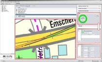
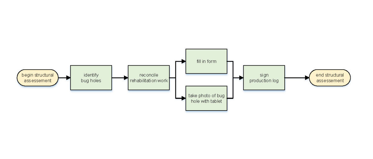
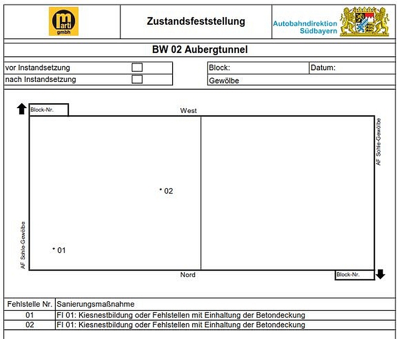
In model-based condition recording, recording on site (Fig. 7) and processing in the site office are not differentiated. The first process steps to identify defects and agree repair measures are identical with the conventional procedure, but the documentation is carried out using a site tablet, which is used for photo documentation as well as to produce the protocol. The protocol (Figs. 8 + 9) is produced using an entry form. In the first step, 3D model and condition protocol are linked, with filter functions and selection options enabling uncomplicated and rapid assignment of building elements and protocols. In a next step, more details are entered of the status of the works before and after the repair.
Based on the agreed repair plan, the defect type is then selected, e.g. defect with or without maintenance of the concrete cover, corner spalling and honeycombing. Should a change, including to the agreed repair measures, be necessary, then the system is flexibly programmed so that changes can be made without problems. In order to easily find individual defects, these are located with a digital marker in the sketch of the protocol. The defect can also be photo-documented with the camera of the site tablet (see Fig. 1), with automated assignment of the image to the defect. It is just this function that offers a considerable saving potential compared to the conventional procedure, because it is extremely laborious to manually perform each assignment. When the recording of the condition of the invert and vault blocks has been completed, the protocol is digitally signed on site by the contractor and the site supervision. Then the system generates an assignable document description and saves the procedure in the local folder of the site tablet. When the tablet is next connected to the site network outside the tunnel, the data is automatically synchronised with the central database server.
3.4 Comparison
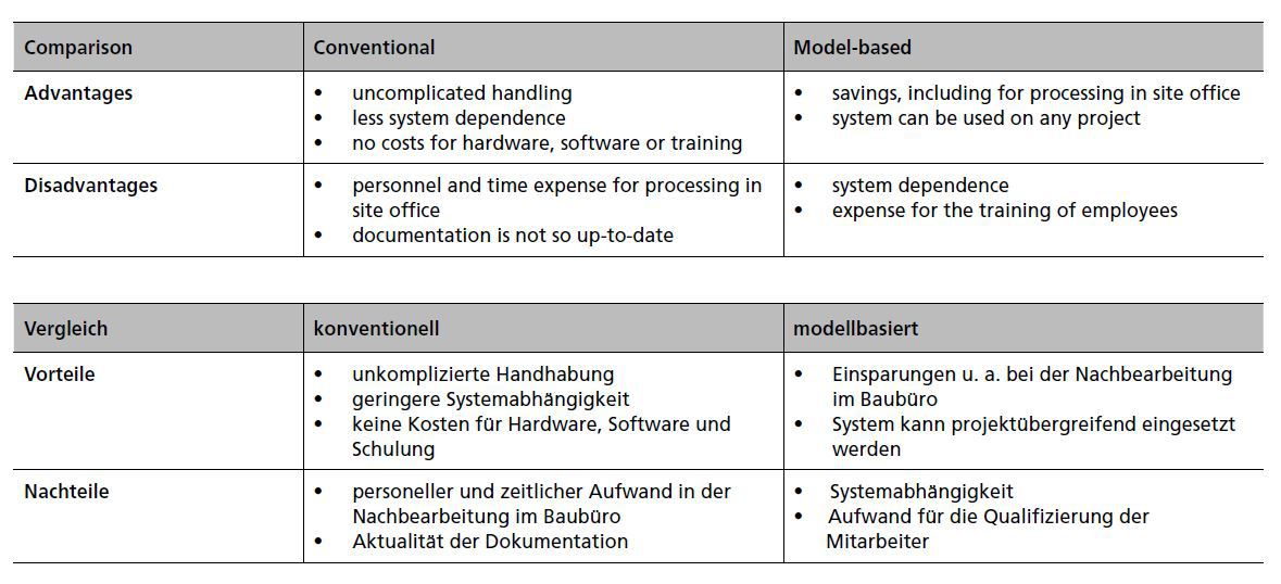
Table 1 collects and compares the advantages and disadvantages of conventional and model-based condition recording. One advantage of conventional condition recording is uncomplicated handling, since the documentation is on paper. There is also no dependence on and no costs for software, hardware or training the employees. In contrast to this, model-based condition recording offers savings in the subsequent processing in the site office. Another significant advantage is that the system can be used again without problems on future sites.
Corresponding to the advantages of the model-based procedure, the conventional procedure has the disadvantage of expense for personnel and time for subsequent processing in the site office. The analog procedure also has the disadvantage of being less up-to-date.
One disadvantage of model-based condition recording that should not be underestimated is its dependence on soft- and hardware. There is not only the risk of programming and data entry mistakes but also that parts of the system or components can fail. A further disadvantage is that the introduction and use of the model-based procedure is associated with training costs.
4 Conclusion
The introduction of innovations is frequently associated with changes to the business process and has a direct effect on the working environment of all parties to a project. The Auberg Tunnel pilot project showed on the one hand what opportunities are opened up by the use of digital applications for condition recording in tunnelling. On the other hand, it was noticed that existing working processes have to be adapted, with the motivation and commitment of the employees being significant for a successful adaptation. The added value of model-based condition recording was noticeable from the first day of use and was accepted positively by all those involved. The user-friendliness of hardware and software plays a decisive role for its acceptance. If the associated added value is not directly noticeable or cannot be appropriately explained, then the challenge of implementation is correspondingly greater. By and large it can be stated that processes could be optimised through the implementation of the described application cases, as can be seen from the reduction of redundant working processes and the time-intensive creation of documents.
References/Literatur