Finne Tunnel: Innovative targeted Resealing of Segment Bore Joints – Part 1
Leaking joints in the tunnel lining were resealed in an innovative fashion in the Finne Tunnel in Thuringia/D. Cause of leaks and possible resealing methods are described and assessed in principle in Part 1. Part 2 deals with the innovative resealing method successfully applied in the Finne Tunnel.
1 Introduction
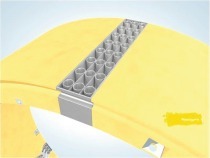
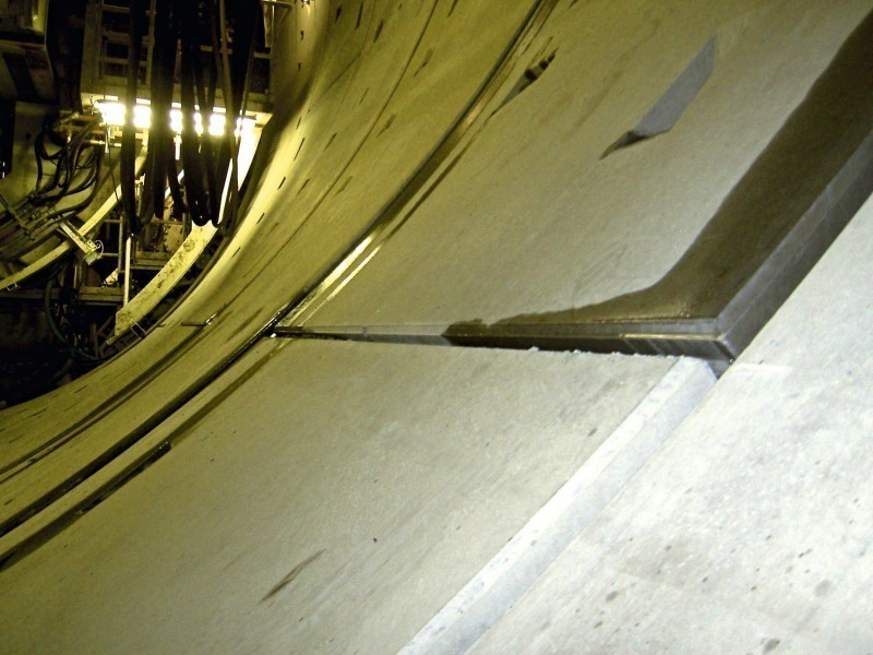
The joints closed by compressed sealing elements between the segments are potential weak points in monocoque tunnel linings (Fig. 1). Joints are practically entirely responsible for establishing the watertightness of a segmental tunnel lining. Generally the joints are sealed by elastomere gaskets installed continuously around the segments. When the ring is assembled the segments are coupled with one another with the sealing elements projecting from the concrete surface compressed to the degree needed to arrive at the sealing effect [1]. Inaccurate assembly or other errors can prevent scheduled compression. Although the sealing elements in such cases are in place they are unable to function completely on account of a lack of compression. Water can intrude should a certain water pressure be exceeded (Fig. 2). This report describes a method to directly reseal leaking joints as applied successfully in the Finne Tunnel.
2 How the Sealing Elements work
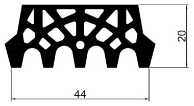
The waterproofing effect of the segment joint seal is based on elastic gaskets, which are compressed against each other and at the same time against the adjoining concrete. Providing compression at every point of a joint is greater than the invasive water pressure, the seal is tight. Then the water cannot penetrate the boundary layer between the compressed sealing elements nor can it find a way around the sealing element. However the seal’s continuity is interrupted at the corners of the segment. The neighbouring seals come up against each other in a longitudinal direction resulting in a joint that transverses the seal. This joint is at right angles to the direction of compression applied during the installation of the ring. The 2 elements have to be compressed against each other in their longitudinal direction so that the joint remains watertight. This is only possible indirectly via the transverse expansion of the elements. The art of profile design involves attaining complete adequate compression in both directions relevant for waterproofing by combining material properties, external form and internal cavities.
3 Possible weak Points in the Waterproofing System for the Segment Joints
The highest demands are placed on the geometrical accuracy of the segments and sealing frames. The sealing effect and the mechanical properties of the sealing elements are investigated by firmly prescribed test methods and must fulfil certain criteria. Even certain inadequacies during installation are simulated in the test programme [2, 3]. As a result, adequate sealing against the dimensioned water pressure can be presupposed providing segment assembly adheres to the tolerance limits.
Should leaks recur at frequent intervals then this is mainly caused by assembly errors. These errors in some cases can be classified as exceeding tolerance specifications. However, they can also result from assembly situations within the tolerances, which have not been classified and thus have not been considered in the tests. Quite apart from this of course, damage to the segments or the sealing frames during assembly as well as a result of subsequent strains can cause leaks.
3.1 Exceeding Tolerances
Tolerances can be exceeded owing to:
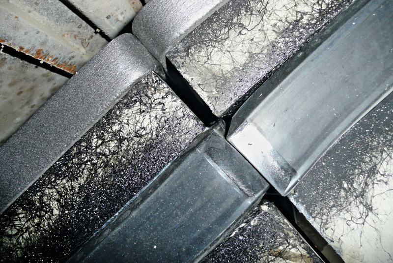
Major misalignments between the 2 opposite compressed sealing elements resulting in a minimal or completely lacking contact area (Fig. 3).
A major gap between the segments resulting in insufficient compression of the sealing elements.
3.2 Other assembly-related geometrical Errors
Other assembly-related geometrical errors can be:
Major difference in height between the sealing frame corners of neighbouring segments of a ring on account of imprecise assembly. When the next ring is assembled, a T-joint with locally inadequate compression or even a gap in the sealing system ensues.
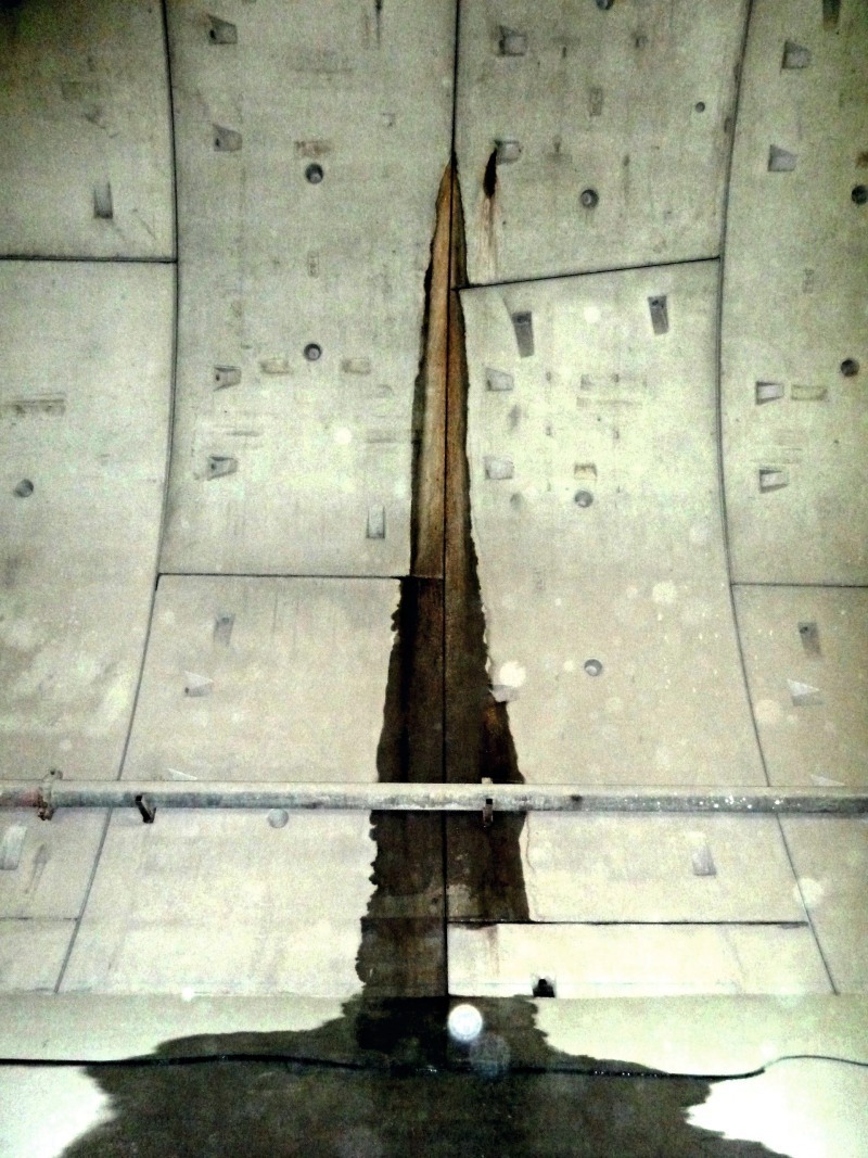
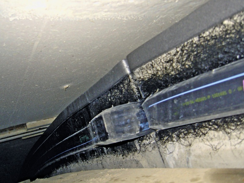
Extreme difference in height of the sealing frame corners on account of the sealing frame loosening from bonding and misalignment along the sealing groove (Fig. 4), thus resulting in a gap in the sealing system.
Bulging and loosening of the sealing frame in the annular joint close to a longitudinal joint as a result of its scheduled compression. The actual cause is attributable to the unsuitable shape of the frame corners. Loosening from the groove can also lead to leakage just as a local surplus of material.
False positioning of the sealing element as a result of bending, becoming dirty or lateral misalignment owing to a faulty sequence of movements during ring installation.
3.3 Damage during Installation and subsequent
Damage can be:
The sealing element overexpands, falls out or tears on account of the effect of force given false manipulation.
Deliberate removal by cutting off displaced or loosened sealing frame parts, which project from the face surface of the previously installed ring.
Spalling of the concrete adjacent to the sealing groove resulting from colliding with steel parts of the shield owing to false manipulation of the erector.
Spalling of the concrete adjacent to the sealing groove resulting from unsuitable segment geometry or excessive initial stiffness of the sealing element. The danger of spalling is greatest at the corners of the segment. The exposed position of a corner as such, the special conditions during ring assembly and the frequently higher stiffness of the sealing frame corners make these places particularly susceptible for spalling.
Spalling of the concrete adjacent to the sealing groove resulting from excessive compression of the sealing element should neighbouring ring segments become distorted around their common longitudinal joint. This cause of spalling results from unfavourable interaction between the segment geometry, sealing element stiffness and ring deformation. This is admittedly improbable but cannot be entirely precluded given extremely small hinge neck width and application of sealing elements with a very small chamber volume and high filling level.
3.4 Loss of applied Sealing Element Compression
The compression or pre-tensioning needed for the required sealing effect, which was established in the tests, is perforce secured by the segment geometry and the properties of the sealing element providing the segment is installed correctly. The maximum possible compressions and in turn, tension are attained in the longitudinal joints, providing that the segments that are arranged alongside one another touch. In the annular joints, which are generally provided with thin spacer plates, the plates come together as intended thanks to the thrusting jacks instead of concrete contact. If operated properly these jacks work continuously during ring installation as well. In this way the sustained compression of the segment bores is assured and once the seal has been compressed in the annular joints this can no longer be lost through resilience. At the same time, the action of the thrusting jacks is no guarantee for adequate compression of the seal for all segments of a ring. In the event of premature fitting in the longitudinal joints it is definitely possible that a segment that has just been installed cannot actually be pushed against the neighbouring ring when the thrusting jacks are reapplied. In this way the compression required for the seal in the annular joint is absent.
In contrast to the annular joints the longitudinal joints are compressed only by the erector force. The seal compression attained in this manner must be secured through immediate engagement prior to the removal of the erector. The bolts must accept the seal’s restoring forces until the segment is firmly surrounded by hardened annular gap mortar. Providing the bolts are sufficiently pretensioned it is possible that a portion of the seal compression is lost through resilience. Such stress relief can also result when the bolts are subsequently removed if the segmental bore is inadequately embedded due to faulty filling of the annular gap.
4 Recognising and Correcting weak Points during Driving
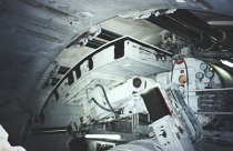
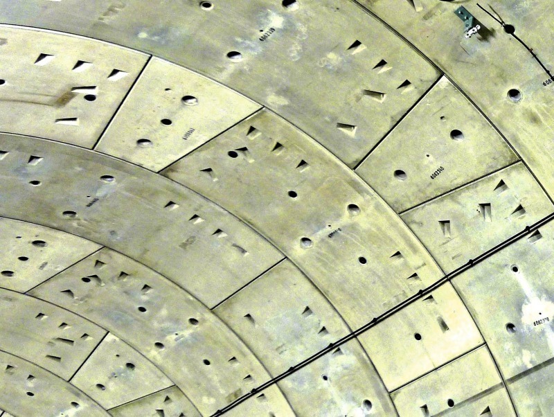
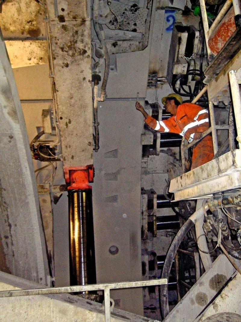
In the previous chapter many possible causes of leaks were described. Apart from system errors such as unsuitable sealing elements, excessively stiff sealing frame corners or faulty segment geometry, the majority of leaks are attributable to errors during ring installation. All deviations from the prescribed tolerances and other assembly instructions are to be understood as errors. However a distinction must be drawn in this case between deviations caused inevitably by driving, say if major directional corrections are required, and errors owing to carelessness. The duration of ring assembly exerts a considerable influence on the rate of advance. It can be substantially shortened thanks to good organisation and routine quite apart from the courage for imperfection. The exact assembly of a segment taking all geometric and sealing technical aspects into account can require a number of attempts and several minutes’ time (Fig. 5). A difference of 10 min or more can be the outcome per ring. The leaks caused by less precise work thus represent the price for attaining a high rate of advance. Thus it is logical that the outlay for resealing operations is carried by the contractor. Providing that the required tightness is permanently arrived at in the final state, it is only a question of economy whether emphasis is placed on avoiding or repairing leaks.
Certainly the optimum lies between the extremes of time-consuming work accurate to the millimetre and the fastest possible ring assembly without considering sealing requirements. It is scarcely worthwhile investing in preventing leaks, providing it is essentially possible to repair individual defects and that their execution following the conclusion of driving does not lie on the critical path. It would certainly be less economic to produce a tunnel bore that leaks practically throughout. In this case resealing operations would be extremely expensive quite apart from influencing the construction time. The feasibility limit for resealing is soon arrived at given particularly large defects together with the risk of reduction in value or acceptance being refused. Consequently it is evident that a certain amount of care is essential for ring assembly. This has to be assured by self-supervision as well as through the client’s construction supervision.
Monitoring directly following installation of the segments is best as most avoidable leaks result during this phase. It is only possible to prevent errors now. Crude warps and excessively wide joints can be identified at once visually and it is easy to correct them through realignment. The next control opportunity comes along after ring assembly is concluded when the evenness of the frontal area and the sealing element’s correct position are examined. Serious errors can still be corrected through partial or complete disassembly of the ring and subsequent reassembly. This represents the final opportunity for correction. Should geometrical errors or water ingresses then be established, the segments can no longer be removed. As a result, strict monitoring of ring assembly including the subsequent checking of the frontal area (ring area) is imperative. Following this check the green light should formally by given to continue driving.
Checking the segment shell behind the tunnelling machine is of secondary importance owing to the lack of correction possibilities. However the systematic processing of assembly errors and water ingresses can at least result in technical changes for subsequent ring assembly and prevent systematic errors being continued. It is also advisable to allocate errors to different driving shifts to differentiate between basic causes and those due to personnel.
5 Possible Resealing Methods and their Rating
5.1 Basic Methods
Subsequent correction of assembly errors leading to leaks is practically excluded in technical terms. A segmental shell that has been completely installed must be accepted as it is. As a result, leaks can only be sealed by an additional sealing element. Essentially various solutions can be entertained for this purpose:
a) Installation of a second sealing system on the outer side independent of the first sealing system. This is the principle adopted by a twin-shell support.
b) Closing the joints on the outer side by grouting, injecting or caulking.
c) Injecting behind the tunnel bore to create a full-scale watertight zone or sealing layer.
d) Injecting behind the joints in order to close the paths of water circulating around the sealing elements from the outside.
Regarding a): Subsequent installation of a second large-area seal on the inner side of the segmental shell is precluded alone on account of a lack of space in the case of a single-shell tunnel lining. The additional costs and hold-ups to construction also speak against such a solution.
Regarding b): Closing the joints at the outer side is essentially a possibility of removing small amounts of leaking water in a controlled manner without pressure. However the method requires continuous control and maintenance. The sealing elements must not be permitted to fall out, and the water paths must be kept open. It goes without saying that the removal of leaking water depends on whether this is permissible in terms of water management and acceptable to the subsequent tunnel operator. Although this concept is feasible it is nonetheless regarded as inferior by the authors. Water pressure-tight joint closure at the outer side without resorting to draining off the leaking water is practically impossible given the segments currently in use or far too complicated and impractical.
Regarding c): Sustained success in sealing the tunnel surrounding area following random grouting can only be arrived accidently. Substantial application of material, the need to drill through the segments on numerous occasions and possible environmental dangers stand opposed to a slight probability of success. Admittedly injections are customary for restraining a bulkhead or damming rings in water management but unsuitable for producing a tight segment shell.
Regarding d): Ultimately it is only possible to accomplish the complete repair if the defect is entirely closed. Suitable sealing material must be transported to the very spot, where it can effectively interrupt the existing water path. The more effectively this is carried out, the greater the chance of success and the lower the consumption of material are. In the following the various possible techniques for targeted application of grout material to the joints are described.
5.2 Applying Injection Material to the Joints
The sealing elements are located in the segment joints close to the outer edge of the segment. A foam strip is attached to the extreme edge to prevent annular gap mortar from penetrating the joint (Fig. 6). A sealing agent, which must plug or cement the leaks in the joint seal, must first of all, be placed in the joint gap between the seal and foam strip. This can be accomplished in several ways:
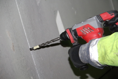
a) Inclined drilling through the segment and direct grouting of the injection material.
b) Radial drilling through the segment next to the joint.
c) Furnishing selected segments or all of them with an injection system in case of need.
d) Drilling a radial grouting channel through the compressed element.
Regarding a): The injection material can spread far into the grid formed by the annular and longitudinal joints given corresponding pressure and application of material. Thus, in this way in theory, a leak remote from the grouting point can be reached and dealt with. Depending on the nature and the setting time of the injection material, however, technical and economic limits are posed. An agent that becomes viscous or stiff too quickly does not reach the source of the leak; with a material that is highly fluid the pressure needed to plug the defect cannot be attained in spite of high material consumption. The enormous technical outlay for drilling and damage to the segment including its reinforcement are the main arguments often put forward against inclined drilling.
Regarding b): Radial drilling through the segment next to the joint is considerably easier in technical terms than inclined drilling. Drilling into the reinforcement can be completely or largely avoided. However the hole drilled emerges on the segment outer surface alongside the annular gap mortar. The grouted injection material spreads from there into the pores of the mortar and into a possible gap between the segment outer surface and the mortar. Should it reach the nearby joint, it must still negotiate the shield tail grease and the compressed foam strip there to arrive at its intended destination. Naturally the chances of success for such extreme indirect grouting are very slight. Material consumption can be very low if no path for it to spread is found. It can also be extremely high without the sealing objective ever being reached.
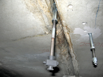
Regarding c): To activate the injection system a screw cap is opened or a defined part of the segment inner surface drilled in order to access a hose that had been concreted in position (Fig. 7). This hose runs right into the flank of the area to be grouted behind the seal. In this manner the same goal is achieved as is the case with inclined drilling without the complication of highly accurate drilling and without damage to the segment. The increased production costs for the segment represent a disadvantage. As a result in cases of application hitherto only individual segments have been furnished with an injection system, e.g. 2 per ring or only every second ring at the most. It was presupposed that the highly fluid grouting agent spreads sufficiently throughout the system of longitudinally and transversely running outer joints. This has in part turned out to be the case although up to 1000 l was needed on occasion to seal a single leak. However there were also cases where sealing was unsuccessful.
Regarding d): With a grouting channel, which runs radially through the middle of a seal comprising 2 elements compressed against each other, applied directly at the location of the leak, the chances of success for resealing are naturally far better than for any other method. At the same time, the outlay is far lower. If such an approach has not become standard practice by now, this is due to an ongoing reluctance to damage sealing elements.
In the Deutsche Bahn Regulation 853.400 [4] the following is cited under tightness requirements (12): “Every discharge of water is to be eliminated by resealing on the outer side of the segmental lining”. This passage relates to the joint seal because the following applies to the segment itself: “Water-bearing cracks have always to be grouted”. The regulation does not describe how resealing on the outer side of the segment is to be executed. It has generally been implied up till now that grouting directly through the joint seal is impermissible. How this was actually performed in the case of the Finne Tunnel is dealt with in Part 2.
6 Summary and Conclusions for the Choice of Resealing Methods in the Finne Tunnel
Targeted resealing at the location of the leak with a grouting channel through the sealing element avoids many disadvantages of the other methods described in spite of the reluctance that has been evident so far. A joint traversing a seal exerts a comparable effect to a cut through the seal. An element, which can render the joint harmless at the frame edge thanks to its deformability characteristics and stiffness, can also completely compensate a cut. In this way it is evident that neither complete continuity nor inviolacy represents the prerequisite for attaining tightness. What really matters is that the compressed sealing frames in their final state are sufficiently compressed throughout.
Drilling a hole through the seal also cannot influence its sealing effect providing compression is retained. Water would at best flow through the opening that was produced. In this connection, inserting a wooden screw into the compressed seal would lead to no water access at all as the compression would be slightly increased without a flow channel being created. Similarly it is possible to conceive drilling straight through and removing material, followed by the insertion of a pipe to restore the former stress state. Once this pipe is reclosed, the original watertight state prevails. However the pipe can also be used to transport sealing material to the seal’s water side. If the leak is eliminated in this way, ultimately the sealing system is improved in spite of the local damage caused by penetration. If the opening used for installing the sealing material can be reclosed, it is absolutely irrelevant for the sealing effect and does not represent a defect as such.
The photos used in Part 1 as well as the described experiences relating to sources of error and damage stem from various tunnels. In its final state unrestricted serviceability of the lining was attained in all cases. The fundamental observations in Part 1 explain the soundness of penetrating the segment seal in a controlled manner in order to reseal it. Part 2 deals with applying this concept in practice in the Finne Tunnel. The successfully applied example in conjunction with fundamental considerations of waterproofing problems will hopefully encourage further developments as well as the inclusion of this technology in codes of practice.