New Gubrist Tunnel: A Case for BIM
 Quelle/credit: Amberg Engineering
 Quelle/credit: Amberg Engineering
 Quelle/credit: Amberg Engineering
The 3.25 km long Gubrist Tunnel on the Zurich North Bypass (A1) is a neuralgic infrastructure on the Swiss motorway network. As a reaction to the permanent congestion in the twin tunnel that was commissioned in 1985, a third tube as well as ventilation and operating centres are being built. This article explains the project’s characteristics and challenges with particular attention being paid to BIM modelling of the underground operating centre.
Description of Project
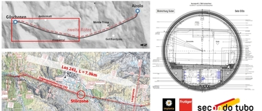
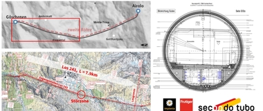
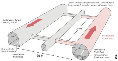
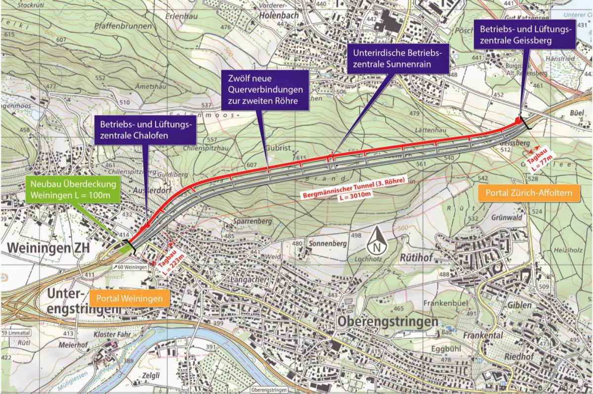
The new tube is a three-lane tunnel running parallel to the existing northern structure and is designed to cater for traffic heading from St. Gallen to Berne. The Gubrist third tube has a total length of 3309.90 m, of which 3010.40 m will be excavated conventionally. The linking cut-and-cover tunnels are 76.90 m long at the Affoltern side and 222.50 m long at the Weiningen side (Fig. 1). Furthermore, a 100 m long covering directly adjoins the tunnel at the Weiningen section.
The horizontal and vertical route alignments largely follow the existing tunnel system. In and around the conventionally excavated tunnel, the overburden ranges from 8 to around 180 m. The distance to the second tube varies from 20 to 50 m. The difference in altitude between the two portals amounts to some 40 m. The tunnel tube is to be excavated dipping from the east portal (Affoltern/Regensdorf) with a gradient of 1.33 %.
Rescue and Safety Concept
Eight accessible cross-passages along with four suitable for vehicles are set up every 300 m linking up with the current second tube. A further cross-passage is to be produced for operating and service personnel at the new underground Sunnenrain operating centre at the level of the utility conduit between the second and third tubes. In addition, a total of 23 combined SOS and hydrant bays set 150 m apart will be installed in the conventionally excavated tunnel. Two further bays will be created in the cut-and-cover section.
Geology and Construction Method
The Gubrist Tunnel is mainly located in rocks belonging to the Upper Freshwater Molasse, which consists of intermittent layers of sandstones, siltstones and marls. The horizontally bedded molasse is covered with layers of soft ground, which comprise moraines and gravels as well as slope deposits at the valley flanks.
The third tube is built by and large solely from the Affoltern/Regensdorf side, where the main installation yard as well as a temporary loading terminal are also set up. The width of the three-lane carriageway comprises 11 m with the clearance height amounting to 4.50 m. The standard profile is arch shaped. The excavated cross-section amounts to 178 m². A crown excavation (approx. 90 m²) followed up by removing the bench and invert is foreseen along the entire length of the conventionally excavated tunnel. Anchors and steel fibre shotcrete are to be applied for supporting the excavation.
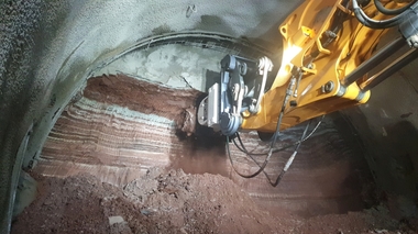
At the Weiningen side, the first 95 m of the conventionally excavated tunnel is located partially in soft ground and below a built-up zone. Here it is essential that a pipe umbrella/spile umbrella is applied as an advance construction measure. This section is driven in reverse so that the main drive remains unaffected.
Inner Lining and Furnishing
A two-shell system comprising an external shotcrete shell and an unreinforced in situ concrete inner shell (35 cm) is intended for securing the excavation and the lining. An extensive drained seal (umbrella seal) is to be laid between the excavation support and the inner vault. The invert area on the other hand will not be sealed. Any accruing underground water will be discharged via ditches at the side of the service duct into the corresponding collector.
The driving zone is separated from the exhaust air duct by a floating, jointless intermediate ceiling, with apertures spaced every 100 m in the intermediate ceiling. Smoke can be removed from the driving zone selectively via these apertures.
In the service duct beneath the carriageway, utility lines (hydrant pipes, underground water and leakage water longitudinal lines and BSA-longitudinal wiring) are set up, which are necessary for operating the tunnel. The main collector for draining the carriageway is to be found in the berm area on the side of the carriageway located at a lower level below the slotted channel. The tunnel is supplied with extinguishing water along its entire length.
Complex Operating Centres
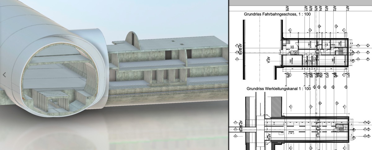
Altogether, three new operating centres and two new ventilation centres are to be produced, each of which will be located at a portal. The underground Sunnenrain operating centre is to be set up at the centre of the tunnel in the proximity of the service bay. This roughly 30 m long operating centre possesses an excavated cross-section of approx. 155 m². The centre’s geometry is split up into three levels. The centre can be accessed at the lowest level, the rooms with the electromechanical equipment are to be found in the middle and upper levels. As these centres are very complex structures, 2D plans are frequently inadequate. Furthermore, Amberg Engineering places great importance on safe planning. Requirements regardig planning peak especially during the execution phase. In order to be able to fulfil them, it was decided to carry out the project based on BIM modelling.
BIM Modelling facilitates Planning and Execution
Since 2017, Amberg Engineering has produced 3D models of tunnels and the underground centre parametrically in coordination with the level of detail 300–400. This enables the configuration of the systems to be interpreted better and diminishes the error rate during planning. In addition, parametrisation of the 3D elements facilitates speedier adjustments, which exerts a positive effect on controlling costs.
By implementing a BIM environment, the project team was able to optimise the planning work flow and for reaching a decision. Through the support of automatic collision tests as well as virtual programming, engineers and modellers are in a position to identify and eliminate problems faster. The solutions are processed by a model-based collaboration tool – in a so-called Common Data Environment (CDE). Although some of those engaged in the project had never previously worked in a BIM environment, they were able to catch up quickly through intensive training. Furthermore, the 3D models enabled the complex systems to be better visualised than would have been the case with 2D diagrams (Fig. 2).
BIM also supported Calculating Statics
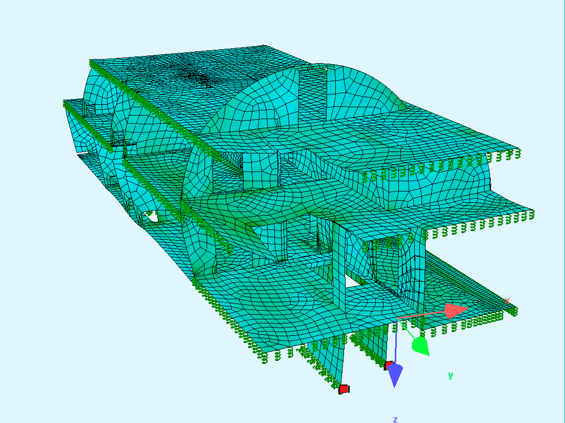
A further BIM environment application related to calculating the statics for the internal supporting structure (supports, walls and ceilings). This was accomplished by importing the 3D model of the Sunnenrain Centre into the Sofistik calculation software, which worked out static methods in keeping with the Finite Element Method (FEM) (Fig. 3).
BIM on the Construction Site
In addition, it is possible to generate any desired cross-section or two-dimensional CAD plan based on the three-dimensional BIM model, which may be required on-site during the course of the project. These electronic plans, which can be viewed on laptop or tablet, are linked with the 3D model. In this way, users can switch between the 2D and 3D presentation according to need. A further great advantage is that the site coordination and defect management can partially be fulfilled via the site software “BIM 360 Field”.
“Lessons learned” and Outlook
The initial costs represent a challenge for applying BIM technology: training courses, software and the acquisition of the necessary hardware involve time and resources. Furthermore, those involved in the project must keep themselves constantly updated to be in a position to function in the BIM environment as e.g. BIM modellers, coordinators or managers.
Although the initial outlay for BIM projects is not inconsiderable, it is well worthwhile when the subsequent savings during the complete life cycle of a structure are taken into consideration. Thanks to the latest developments in augmented, virtual and mixed reality, in future, BIM models will play a decisive role in the management and maintenance of a structure. Nonetheless, BIM is still a relatively new method, which conceals certain risks and responsibilities. In order to overcome these, it is essential that project managers communicate to their teams in a transparent manner the actual targets they are pursuing with their work in a BIM environment.